patent · US5979418
Apparatus for processing fuel vapor in internal combustion engine equipped with supercharger
9 November 1999
Page 1 — bibliographic record
United States Patent (19) 11 Patent Number: 5,979,418 Saruwatari et al. (45) Date of Patent: Nov. 9, 1999 54 APPARATUS FOR PROCESSING FUEL 5,103,794 4/1992 Shiraishi ................................. 123/520 WAPOR IN INTERNAL COMBUSTION 5,183,023 2/1993 Hanson ... ... 123/519 ENGINE EQUIPPED WITH SUPERCHARGER 5,377,644 1/1995 Rohn ... ... 123/520 5,390,645 2/1995 Cook ... ... 123/520 75 Inventors: Masayuki Saruwatari; Junichi 5,411,004 5/1995 Busato .................................... 123/520 Furuya, both of Atsugi, Japan 5,474,047 12/1995 Cochard .................................. 123/520
FOREIGN PATENT DOCUMENTS
73 Assignee: Unisia Jecs Corporation, Atsugi, Japan
21 Appl. No.: 09/205,099 Primary Examiner-Carl S. Miller
Attorney, Agent, or Firm-Foley & Lardner
30 Foreign Application Priority Data
Dec. 16, 1997 JP Japan .................................... 9-346583 A three-way valve is mounted in the middle of a bypass passage bypassing the upstream and downstream of a (51) Int. Cl. ............................................... F02M 33/02 compressor, and a purge passage is connected to the three 52 U.S. Cl. ............................................. 1231519; 123/383 way valve. When the negative throttle pressure is equal to or 58 Field of Search ..................................... 129/520,519, above a predetermined value (close to vacuum), the recir 129/518, 516, 521, 198 D, 383 culation of the Supercharged pressure is performed through the bypass passage. On the other hand, when the negative 56) References Cited throttle pressure is below the predetermined value, the
purging of the canister is performed on the upstream Side of the compressor through the bypass passage.
4,446,940 5/1984 Sakakibara .............................. 123/383 4,541,396 9/1985 Sato ........................................ 123/383 10 Claims, 4 Drawing Sheets
17 O 22
Page 2
Drawing sheet — no readable text.
Page 3
ESTMATE NEGATIVE
THROTTLE PRESSURE
YES
PRESSURE IS CLOSE
ESCE > FEEPETERMINED
PRESSURE
S4 S3
SWITCH THREE-WAY VALVE SWITCH THREE-WAY VALVE
TO PERFORMPURGING TO PERFORM
TO UPSTREAM SIDE OF RECERCULATION OF
COMPRESSOR SUPERCHARGED PRESSURE
CAL CULATE REGUESTED PURGE
FLOW RATE
REGUESTED PURGE FLOW RATE
RETURN
Page 4
Drawing sheet — no readable text.
Page 5
ESTMATE NEGATIVE
THROTTLE PRESSURE
YES
NEGATIVE THROTTLE
PRESSURE IS CLOSE
NEGATIVE PREDETERMINED TO VACUUM
THROTTLE 2
PRESSURE VALUE
SWITCH THREE-WAY WALVE SWITCH THREE-WAY WALVE
TO PERFORMPURGING TO PERFORM
TO UPSTREAM SIDE OF RECIRCULATION OF
COMPRESSOR SUPERCHARGED PRESSURE
S 17 S 14
CALCULATE REGUESTED CALCULATE REGUESTED
PURGE FLOW RATE PURGE FLOW RATE
S 18 S 15
RECQUESTED PURGE FLOW RATE
REGUESTED PURGE FLOW RATE
RETURN
Page 6
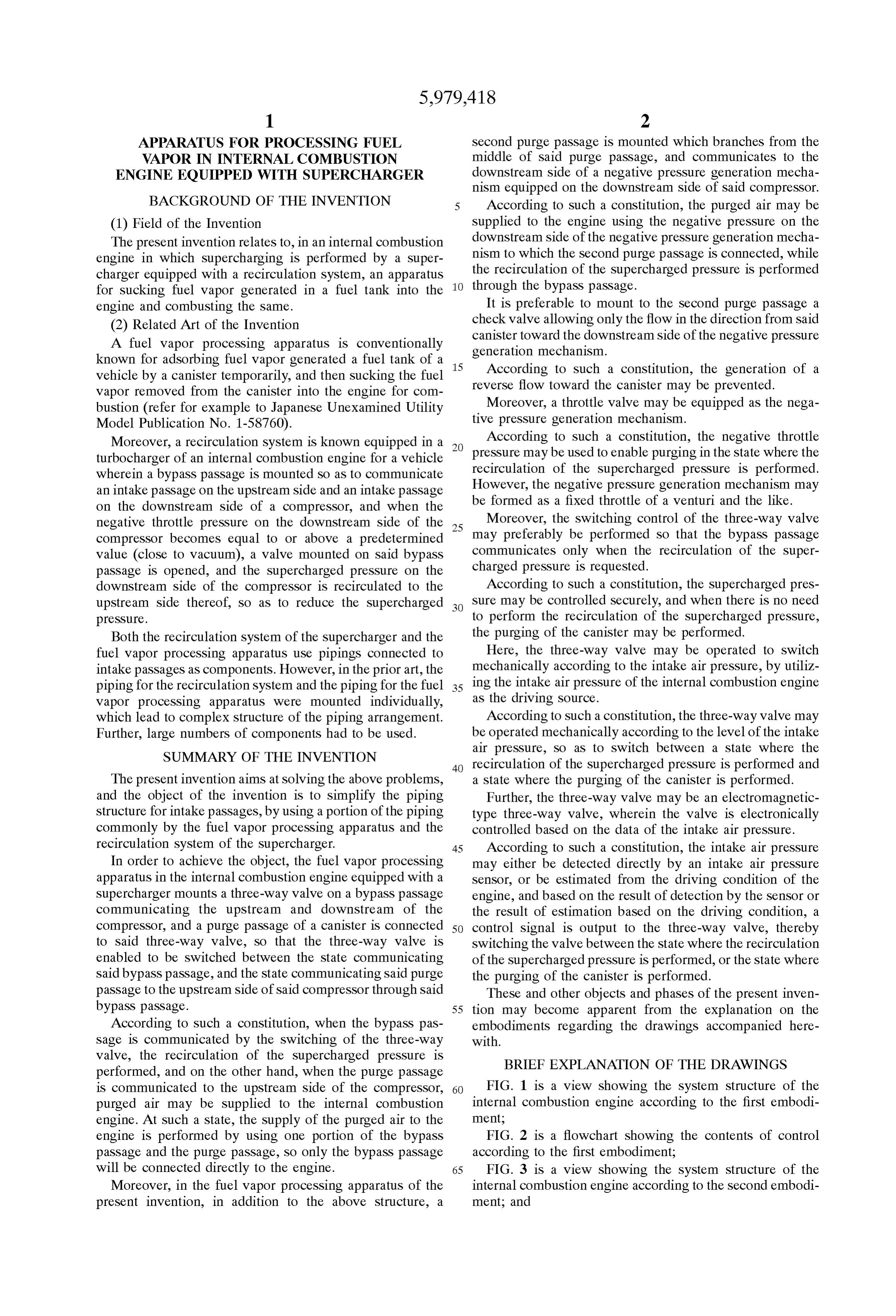
APPARATUS FOR PROCESSING FUEL Second purge passage is mounted which branches from the WAPOR IN INTERNAL COMBUSTION middle of Said purge passage, and communicates to the ENGINE EQUIPPED WITH SUPERCHARGER downstream Side of a negative preSSure generation mecha nism equipped on the downstream Side of Said compressor.
BACKGROUND OF THE INVENTION According to Such a constitution, the purged air may be (1) Field of the Invention Supplied to the engine using the negative pressure on the The present invention relates to, in an internal combustion downstream Side of the negative pressure generation mecha engine in which Supercharging is performed by a Super nism to which the Second purge passage is connected, while charger equipped with a recirculation System, an apparatus the recirculation of the Supercharged pressure is performed for Sucking fuel vapor generated in a fuel tank into the through the bypass passage.
engine and combusting the Same. It is preferable to mount to the Second purge passage a (2) Related Art of the Invention check valve allowing only the flow in the direction from said A fuel vapor processing apparatus is conventionally canister toward the downstream Side of the negative preSSure known for adsorbing fuel vapor generated a fuel tank of a 15 generation mechanism.
According to Such a constitution, the generation of a vehicle by a canister temporarily, and then Sucking the fuel
Vapor removed from the canister into the engine for com reverse flow toward the canister may be prevented. bustion (refer for example to Japanese Unexamined Utility tiveMoreover, pressure a throttle Valve may be equipped as the nega generation mechanism.
Model Publication No. 1-58760).
Moreover, a recirculation System is known equipped in a According to Such a constitution, the negative throttle turbocharger of an internal combustion engine for a vehicle preSSure may be used to enable purging in the State where the wherein a bypass passage is mounted So as to communicate recirculation of the Supercharged pressure is performed. an intake passage on the upstream Side and an intake passage However, the negative pressure generation mechanism may on the downstream Side of a compressor, and when the be formed as a fixed throttle of a venturi and the like. negative throttle pressure on the downstream Side of the 25 Moreover, the Switching control of the three-way valve compressor becomes equal to or above a predetermined may preferably be performed So that the bypass passage value (close to vacuum), a valve mounted on Said bypass communicates only when the recirculation of the Super passage is opened, and the Supercharged pressure on the charged pressure is requested.
downstream Side of the compressor is recirculated to the According to Such a constitution, the Supercharged pres upstream Side thereof, So as to reduce the Supercharged Sure may be controlled Securely, and when there is no need preSSure. to perform the recirculation of the Supercharged pressure, Both the recirculation System of the Supercharger and the the purging of the canister may be performed. fuel Vapor processing apparatus use pipings connected to Here, the three-way valve may be operated to Switch intake passages as components. However, in the prior art, the mechanically according to the intake air pressure, by utiliz piping for the recirculation System and the piping for the fuel 35 ing the intake air preSSure of the internal combustion engine Vapor processing apparatus were mounted individually, as the driving Source.
which lead to complex Structure of the piping arrangement. According to Such a constitution, the three-way valve may Further, large numbers of components had to be used. be operated mechanically according to the level of the intake SUMMARY OF THE INVENTION air pressure, So as to Switch between a State where the 40 recirculation of the Supercharged pressure is performed and
The present invention aims at Solving the above problems, a State where the purging of the canister is performed. and the object of the invention is to simplify the piping Further, the three-way valve may be an electromagnetic Structure for intake passages, by using a portion of the piping type three-way valve, wherein the valve is electronically commonly by the fuel vapor processing apparatus and the controlled based on the data of the intake air pressure. recirculation System of the Supercharger. 45 According to Such a constitution, the intake air preSSure In order to achieve the object, the fuel vapor processing may either be detected directly by an intake air preSSure apparatus in the internal combustion engine equipped with a Sensor, or be estimated from the driving condition of the Supercharger mounts a three-way valve on a bypass passage engine, and based on the result of detection by the Sensor or communicating the upstream and downstream of the the result of estimation based on the driving condition, a compressor, and a purge passage of a canister is connected 50 control Signal is output to the three-way valve, thereby to Said three-way valve, So that the three-way valve is Switching the valve between the State where the recirculation enabled to be Switched between the State communicating of the Supercharged pressure is performed, or the State where Said bypass passage, and the State communicating Said purge the purging of the canister is performed. passage to the upstream Side of Said compressor through Said These and other objects and phases of the present inven bypass passage. 55 tion may become apparent from the explanation on the According to Such a constitution, when the bypass pas embodiments regarding the drawings accompanied here Sage is communicated by the Switching of the three-way with.
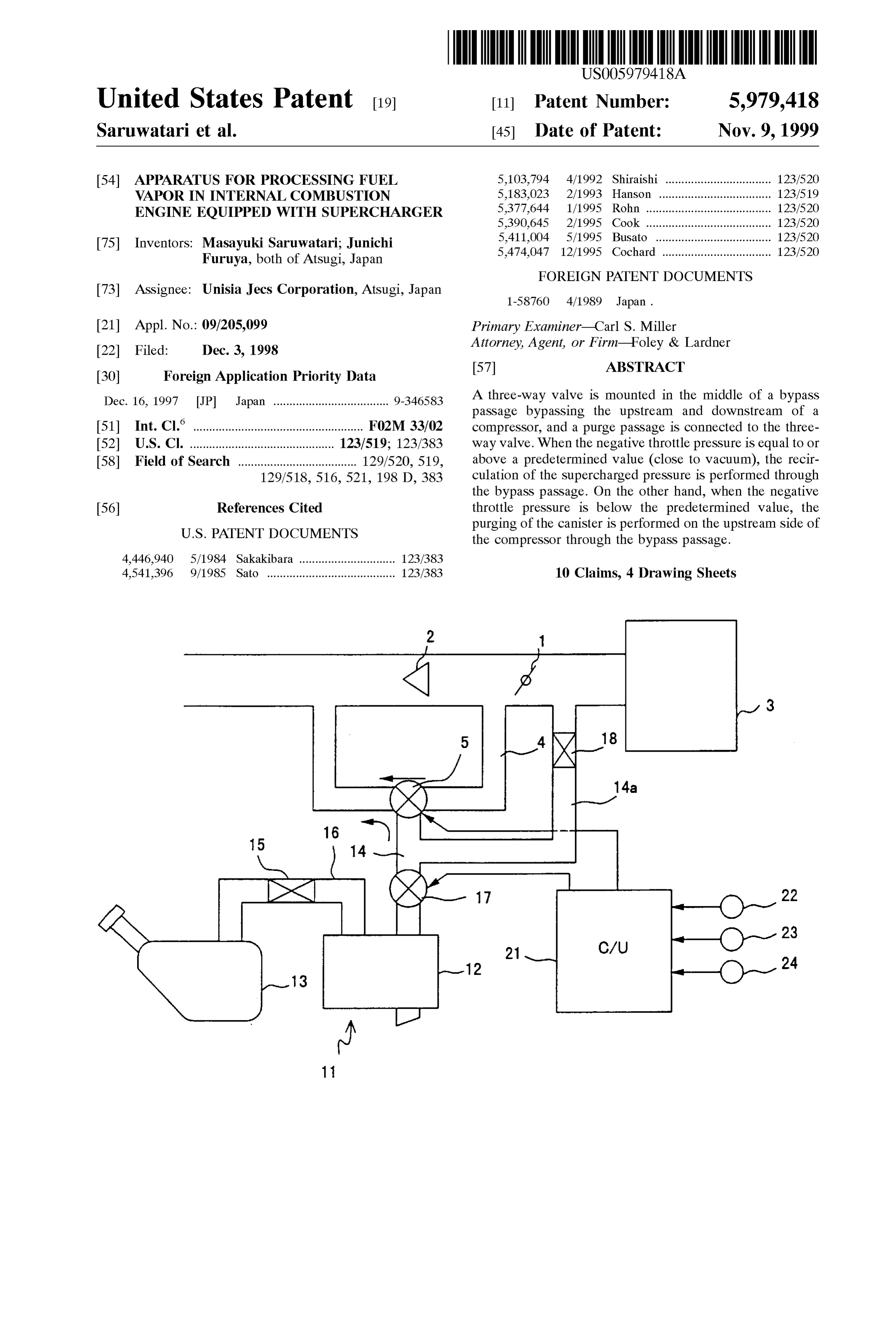
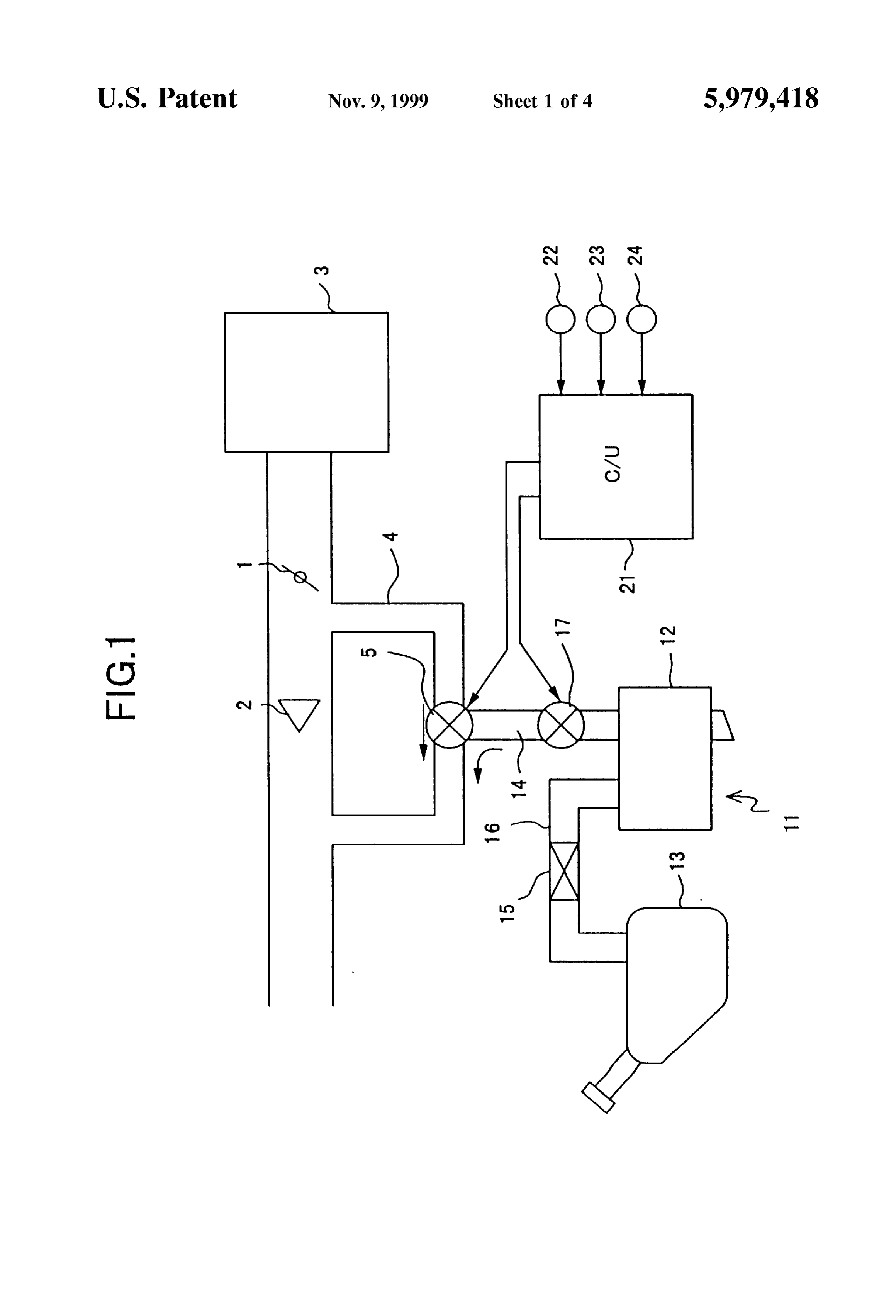
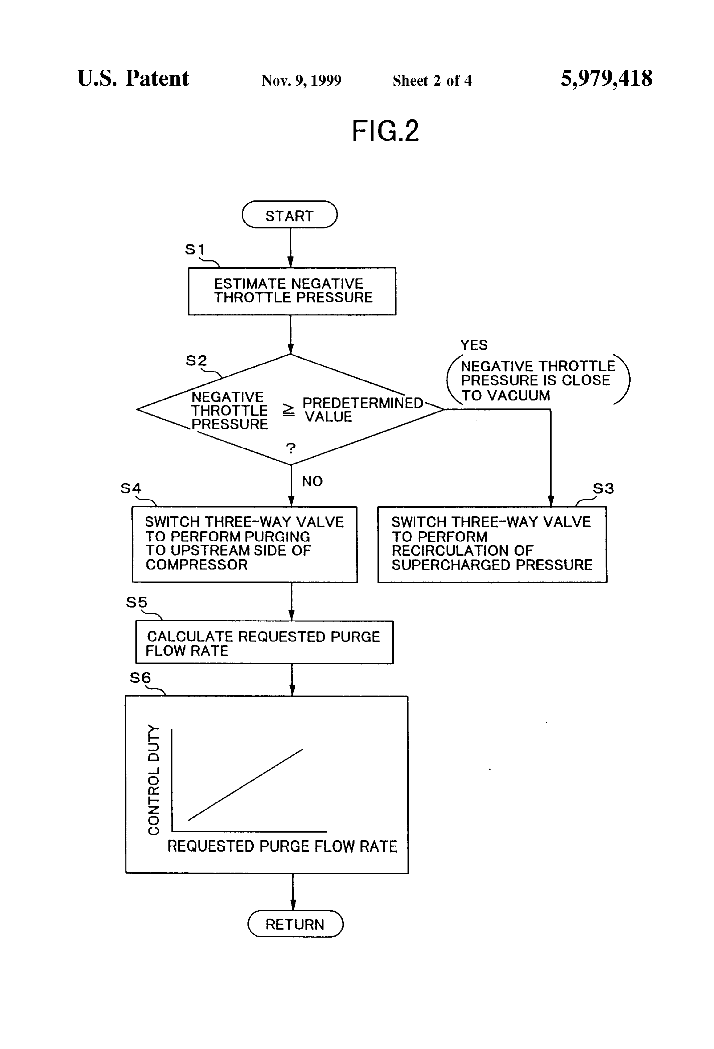
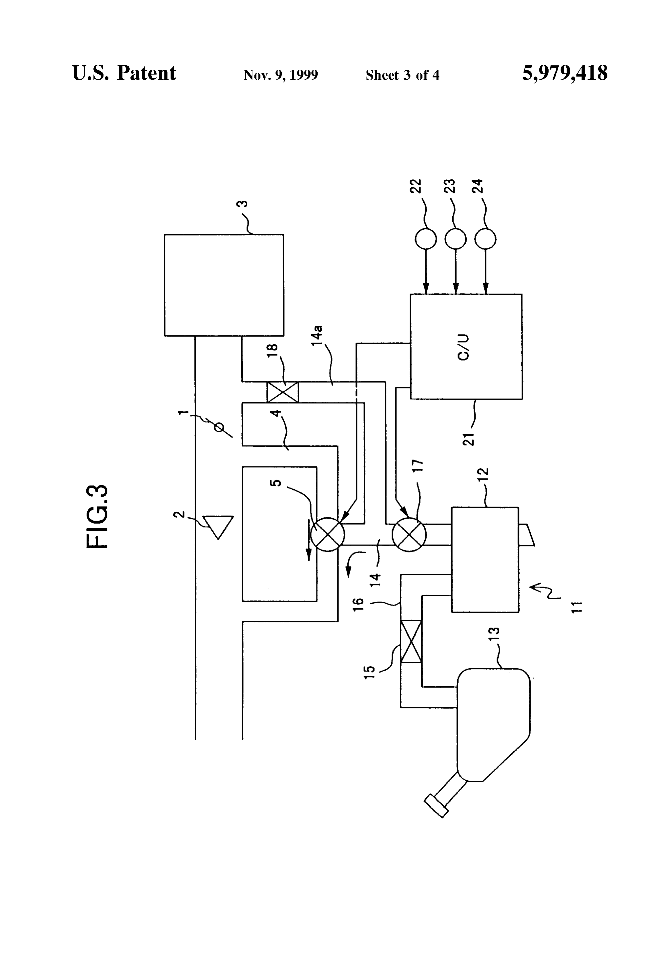
Valve, the recirculation of the Supercharged preSSure is BRIEF EXPLANATION OF THE DRAWINGS performed, and on the other hand, when the purge passage is communicated to the upstream Side of the compressor, 60 FIG. 1 is a view showing the system structure of the purged air may be Supplied to the internal combustion internal combustion engine according to the first embodi engine. At Such a State, the Supply of the purged air to the ment, engine is performed by using one portion of the bypass FIG. 2 is a flowchart showing the contents of control passage and the purge passage, So only the bypass passage according to the first embodiment;
will be connected directly to the engine. 65 FIG. 3 is a view showing the system structure of the Moreover, in the fuel vapor processing apparatus of the internal combustion engine according to the Second embodi present invention, in addition to the above Structure, a ment; and
Page 7
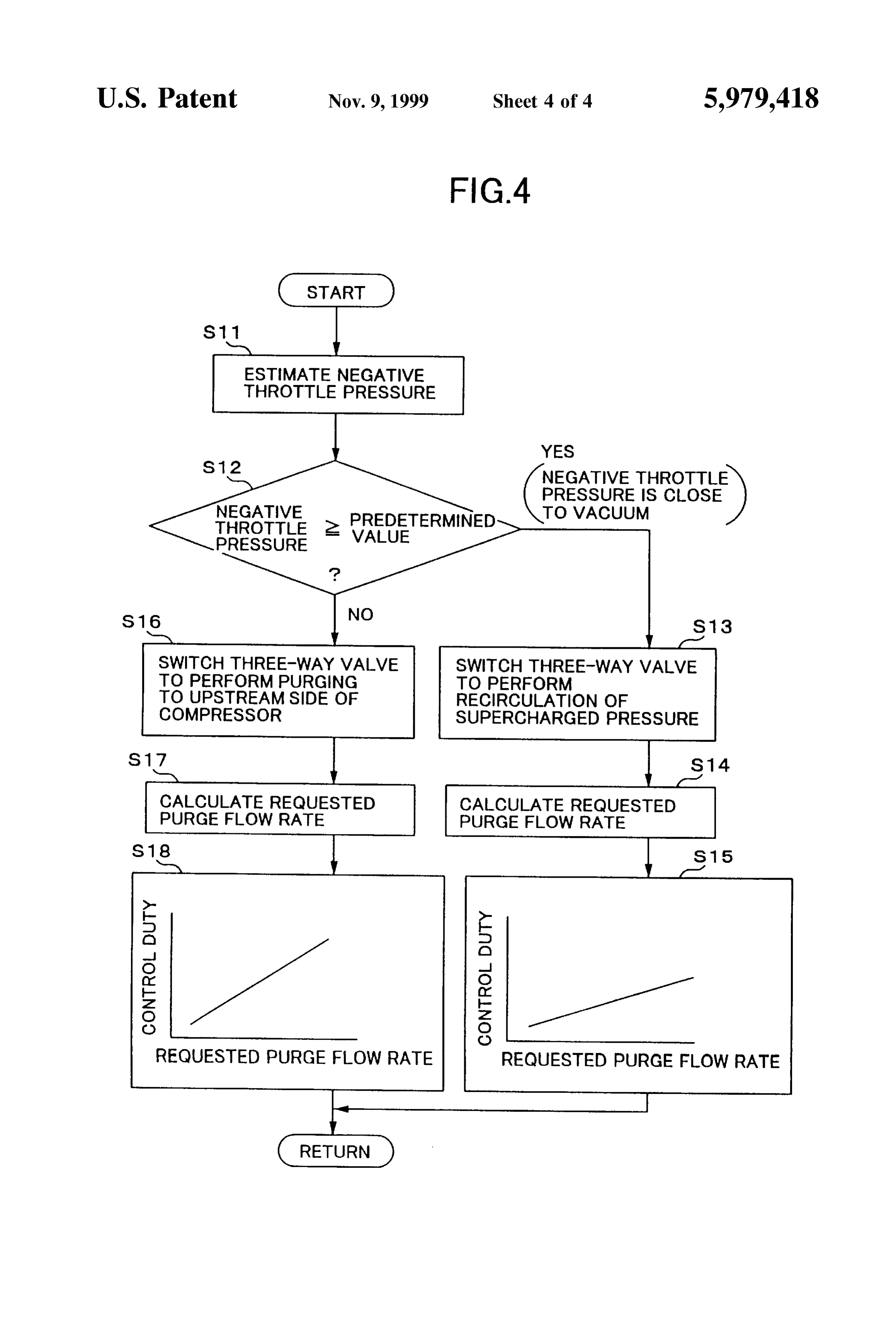
FIG. 4 is a flowchart showing the contents of control bypass passage 4, thereby recirculating the Supercharged according to the Second embodiment. preSSure on the downstream Side of the compressor 2 to the
DETAILED DESCRIPTION OF THE
upstream side thereof (Switching device).
PREFERRED EMBODIMENT On the other hand, when the negative throttle preSSure is below the predetermined value (when the intake air pressure
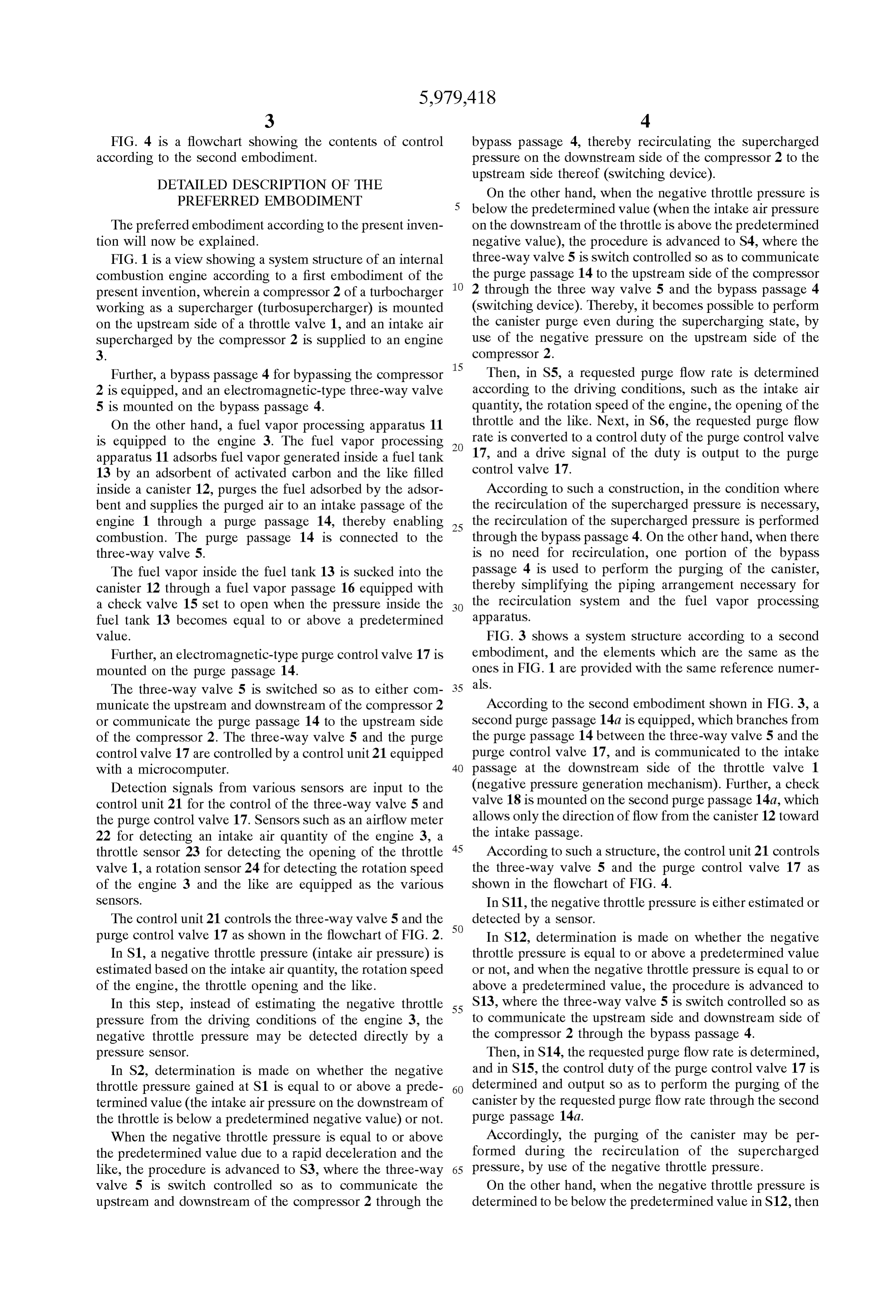
The preferred embodiment according to the present inven on the downstream of the throttle is above the predetermined tion will now be explained. negative value), the procedure is advanced to S4, where the FIG. 1 is a view showing a System Structure of an internal three-way valve 5 is Switch controlled So as to communicate combustion engine according to a first embodiment of the the purge passage 14 to the upstream Side of the compressor present invention, wherein a compressor 2 of a turbocharger 2 through the three way valve 5 and the bypass passage 4 working as a Supercharger (turboSupercharger) is mounted (Switching device). Thereby, it becomes possible to perform on the upstream Side of a throttle valve 1, and an intake air the canister purge even during the Supercharging State, by Supercharged by the compressor 2 is Supplied to an engine use of the negative preSSure on the upstream side of the 3. compressor 2.
Further, a bypass passage 4 for bypassing the compressor Then, in S5, a requested purge flow rate is determined 2 is equipped, and an electromagnetic-type three-way valve according to the driving conditions, Such as the intake air 5 is mounted on the bypass passage 4. quantity, the rotation Speed of the engine, the opening of the On the other hand, a fuel vapor processing apparatus 11 throttle and the like. Next, in S6, the requested purge flow is equipped to the engine 3. The fuel vapor processing rate is converted to a control duty of the purge control valve apparatus 11 adsorbS fuel vapor generated inside a fuel tank 17, and a drive signal of the duty is output to the purge 13 by an adsorbent of activated carbon and the like filled control valve 17.
inside a canister 12, purges the fuel adsorbed by the adsor According to Such a construction, in the condition where bent and Supplies the purged air to an intake passage of the the recirculation of the Supercharged pressure is necessary, engine 1 through a purge passage 14, thereby enabling 25 the recirculation of the Supercharged pressure is performed combustion. The purge passage 14 is connected to the through the bypass passage 4. On the other hand, when there three-way valve 5. is no need for recirculation, one portion of the bypass The fuel vapor inside the fuel tank 13 is sucked into the passage 4 is used to perform the purging of the canister, canister 12 through a fuel vapor passage 16 equipped with thereby Simplifying the piping arrangement necessary for a check valve 15 set to open when the pressure inside the the recirculation System and the fuel vapor processing fuel tank 13 becomes equal to or above a predetermined apparatuS.
value. FIG. 3 shows a System structure according to a Second Further, an electromagnetic-type purge control Valve 17 is embodiment, and the elements which are the same as the mounted on the purge passage 14. ones in FIG. 1 are provided with the same reference numer The three-way valve 5 is Switched so as to either com als. 35 municate the upstream and downstream of the compressor 2 According to the second embodiment shown in FIG. 3, a or communicate the purge passage 14 to the upstream side Second purge passage 14a is equipped, which branches from of the compressor 2. The three-way valve 5 and the purge the purge passage 14 between the three-way valve 5 and the control valve 17 are controlled by a control unit 21 equipped purge control valve 17, and is communicated to the intake with a microcomputer. 40 passage at the downstream Side of the throttle valve 1 Detection signals from various Sensors are input to the (negative pressure generation mechanism). Further, a check control unit 21 for the control of the three-way valve 5 and Valve 18 is mounted on the Second purge passage 14a, which the purge control valve 17. Sensors Such as an airflow meter allows only the direction of flow from the canister 12 toward 22 for detecting an intake air quantity of the engine 3, a the intake passage.
throttle sensor 23 for detecting the opening of the throttle 45 According to Such a structure, the control unit 21 controls Valve 1, a rotation Sensor 24 for detecting the rotation Speed the three-way valve 5 and the purge control valve 17 as of the engine 3 and the like are equipped as the various shown in the flowchart of FIG. 4.
SCSOS. In S11, the negative throttle pressure is either estimated or The control unit 21 controls the three-way valve 5 and the 50 detected by a Sensor.
purge control valve 17 as shown in the flowchart of FIG. 2. In S12, determination is made on whether the negative In S1, a negative throttle pressure (intake air pressure) is throttle pressure is equal to or above a predetermined value estimated based on the intake air quantity, the rotation Speed or not, and when the negative throttle pressure is equal to or of the engine, the throttle opening and the like. above a predetermined value, the procedure is advanced to In this Step, instead of estimating the negative throttle 55 S13, where the three-way valve 5 is Switch controlled so as preSSure from the driving conditions of the engine 3, the to communicate the upstream Side and downstream Side of negative throttle pressure may be detected directly by a the compressor 2 through the bypass passage 4. preSSure Sensor. Then, in S14, the requested purge flow rate is determined, In S2, determination is made on whether the negative and in S15, the control duty of the purge control valve 17 is throttle pressure gained at S1 is equal to or above a prede 60 determined and output So as to perform the purging of the termined value (the intake air pressure on the downstream of canister by the requested purge flow rate through the Second the throttle is below a predetermined negative value) or not. purge passage 14a.
When the negative throttle pressure is equal to or above Accordingly, the purging of the canister may be per the predetermined value due to a rapid deceleration and the formed during the recirculation of the Supercharged like, the procedure is advanced to S3, where the three-way 65 preSSure, by use of the negative throttle pressure. valve 5 is Switch controlled so as to communicate the On the other hand, when the negative throttle preSSure is upstream and downstream of the compressor 2 through the determined to be below the predetermined value in S12, then
Page 8
S 6 the procedure is advanced to S16, where the three-way valve 3. A fuel vapor processing apparatus of an internal com 5 is Switch controlled So as to communicate the purge bustion engine equipped with a Supercharger according to passage 14 to the upstream Side of the compressor 2 through claim 1, wherein Said Switching means operates Said three the bypass passage 4. way valve to Switch mechanically according to an intake air Then, the requested purge flow rate is calculated in S17, preSSure of Said internal combustion engine, using Said and in S18, the control duty of the purge control valve 17 is intake air pressure as a driving Source. determined and output So as to perform the purging of the 4. A fuel vapor processing apparatus of an internal com canister to the upstream Side of the compressor 2 through the bustion engine equipped with a Supercharger according to purge passage 14 and the bypass passage 4. claim 1, wherein Said three-way valve is an electromagnetic When the apparatus adopts the Structure to perform the type three-way valve, and Said Switching means controls purging of the canister to the upstream Side of the compres Said three-way valve electronically based on the data of an Sor 2, the purging may be performed even while intake air pressure.
Supercharging, using the negative preSSure on the upstream 5. A fuel vapor processing apparatus of an internal com Side of the compressor 2. 15 bustion engine equipped with a Supercharger according to According to the first and Second embodiments, the claim 1, wherein a check Valve is mounted on Said Second Switching of the three-way valve 5 was controlled electroni purge passage for allowing only the direction of flow from cally. However, the three-way valve may also be driven to Said canister toward the downstream Side of Said negative Switch mechanically by a diaphragm, by introducing the preSSure generation mechanism.
negative throttle pressure (intake air pressure) to the dia 6. A fuel vapor processing apparatus of an internal com phragm. In this case, the determination of the negative bustion engine equipped with a Supercharger according to throttle pressure in the flowcharts of FIG. 2 and FIG. 4 and claim 1, wherein Said negative pressure generation mecha the Switching control of the three-way valve 5 based on the nism is a throttle valve.
determined result should be omitted.
7. A fuel vapor processing apparatus in an internal com
Further, a mechanical Supercharger may be used other 25 bustion engine equipped with a Supercharger, in which than the turbocharger. Supercharging is performed by Said Supercharger equipped Moreover, the compressor may be equipped on the down with a recirculation System for circulating a Supercharged stream side of the throttle valve. In Such a structure, the preSSure on the downstream side of a compressor to the opening and closing of the bypass passage 4 may preferably upstream Side thereof through a bypass passage, comprising: be controlled according to the Supercharged pressure (intake a canister for adsorbing fuel vapor being generated in a air pressure) on the downstream Side of the compressor. fuel tank;
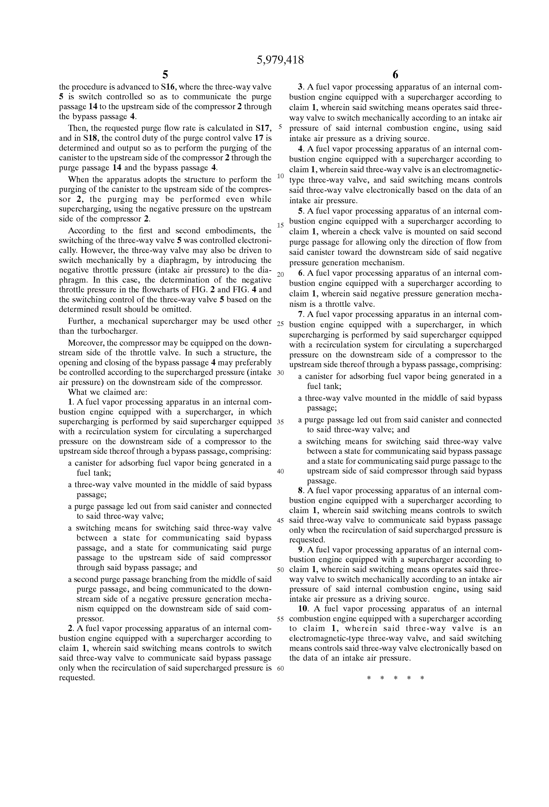
What we claimed are:
1. A fuel Vapor processing apparatus in an internal com a three-way valve mounted in the middle of Said bypass bustion engine equipped with a Supercharger, in which passage,
Supercharging is performed by Said Supercharger equipped 35 a purge passage led out from Said canister and connected with a recirculation System for circulating a Supercharged to Said three-way valve, and preSSure on the downstream side of a compressor to the a Switching means for Switching Said three-way valve upstream Side thereof through a bypass passage, comprising: between a State for communicating Said bypass passage a canister for adsorbing fuel vapor being generated in a and a State for communicating Saidpurge passage to the fuel tank; 40 upstream Side of Said compressor through Said bypass passage.
a three-way valve mounted in the middle of Said bypass 8. A fuel vapor processing apparatus of an internal com passage, bustion engine equipped with a Supercharger according to a purge passage led out from Said canister and connected claim 1, wherein Said Switching means controls to Switch to Said three-way valve; 45 Said three-way valve to communicate Said bypass passage a Switching means for Switching Said three-way valve only when the recirculation of Said Supercharged pressure is between a State for communicating Said bypass requested.
passage, and a State for communicating Said purge 9. A fuel vapor processing apparatus of an internal com passage to the upstream Side of Said compressor bustion engine equipped with a Supercharger according to through Said bypass passage, and 50 claim 1, wherein Said Switching means operates Said three a Second purge passage branching from the middle of Said way valve to Switch mechanically according to an intake air purge passage, and being communicated to the down preSSure of Said internal combustion engine, using Said Stream Side of a negative pressure generation mecha intake air pressure as a driving Source.
nism equipped on the downstream Side of Said com 10. A fuel vapor processing apparatus of an internal preSSor. 55 combustion engine equipped with a Supercharger according 2. A fuel vapor processing apparatus of an internal com to claim 1, where in Said three-way Valve is an bustion engine equipped with a Supercharger according to electromagnetic-type three-way valve, and Said Switching claim 1, wherein Said Switching means controls to Switch means controls Said three-way valve electronically based on Said three-way valve to communicate Said bypass passage the data of an intake air pressure.
only when the recirculation of Said Supercharged pressure is 60 requested. k k k k k
Provenance
- Collection
- Cited prior art
- Original PDF
- patentimages.storage.googleapis.com →
- Filed
- 1998-12-03
- Pages
- 8
- Method
- pdftotext (the PDF's own text layer) + pdftoppm 300dpi page scans
- Source
- Google Patents bibliographic record
- Granted
- 1999-11-09
- Inventors
- Masayuki Saruwatari; Junichi Furuya; Unisia Jecs Corp
- Transcribed from
- patentimages.storage.googleapis.com →