patent · US6003312
Engine
21 December 1999
Page 1 — bibliographic record
United States Patent (19) 11 Patent Number: 6,003,312 Schlichtig (45) Date of Patent: Dec. 21, 1999 54) ENGINE 57 ABSTRACT 76 Inventor: Ralph Cortez Schlichtig, 11212 3rd In accordance with this invention a vapor engine is provided Ave. So., Seattle, Wash. 981.68 having a first piston of a given diameter and a Second piston having a larger diameter than the first piston. Walls are 21 Appl. No.: 09/184,683 provided within which the pistons travel so as to define a first piston Space and a Second piston Space. An apparatus 22 Filed: Nov. 2, 1998 are provided for connecting the first and the Second piston to a power output. A rotary valve, having passageways therein (51) Int. Cl. ................................................ F16D 31/02 for communicating with the first piston Space and with the 52) ... 60/370; 123/59.3; 123/190.1 Second piston Space and for receiving vapor under preSSure 58 Field of Search .............................. 60/370, 404, 407, from an input Source and for discharging exhaust vapor from 60/716; 123/59.1, 59.3, 190.1 the engine, is a part of the combination. Another apparatus is provided for positioning the rotary valve in accordance with the positioning of the first and Second piston, So that 56) References Cited during a first phase power Stroke relative to the first piston, the pressure vapor power input to the first piston Space from
1,731,015 10/1929 Lehman ................................. 123/59.1 first piston power Stroke while exhausting discharge vapor 1,754,509 4/1930 Gilbert ... ... 123/59.1 X from the Second piston Space all during the power Stroke of 1,755,976 4/1930 Williams .. ... 123/59.1 the first piston, and So that during a Second phase power 3,693,351 9/1972 Minkus ..................................... 60/370 Stroke relative to the Second piston Vapor under pressure is 3,885.387 5/1975 Simington ................................. 60/370 applied to the Second piston by a passageway in the rotary 4,171,618 10/1979 Aegerter ................................ 60/370 X Valve, and thus vapor under pressure flows from the first piston Space to the Second piston Space.
Primary Examiner Hoang Nguyen 6 Claims, 3 Drawing Sheets
ZZAAAZZZYZ AZYZZYZZZAS 2
AAAAAAAAAAAATAAAAA %
Page 2
Drawing sheet — no readable text.
Page 3
Drawing sheet — no readable text.
Page 4
Drawing sheet — no readable text.
Page 5
ENGINE Another object of this invention is to provide the afore mentioned vapor power engine Suitable for operation from a
This invention relates to a vapor engine and, more relatively low preSSure ratio by So Valving the engine during particularly, to a two-phase engine having a first piston for an extended power Stroke following the initial power Stroke the intake Stroke and a Second piston of larger diameter for that power vapor enters the larger piston Space during the exhaust Stroke. substantially all of the additional power stroke. BACKGROUND OF THE INVENTION A further object is to provide the aforementioned vapor power engine Suitable for operation from a higher preSSure
The conventional Steam engine is an example of the prior ratio by So Valving the engine during the expansion Stroke art relative to this invention which will be described in detail that vapor within the larger and Smaller piston Spaces hereinafter. If the input pressure with respect to the con adiabatically expands during Substantially all of the expan denser is beyond design pressure one exhausts from the Sion Stroke.
engine to the condenser too early, thus losing engine power and efficiency by exhausting vapor to the condenser that is of Another object of this invention is to reduce the amount heat that must be delivered to the boiler for a given engine at a uSable pressure. If, on the other hand, the pressure is 15 output below the design preSSure, then the pressure of the expanded Such astoa thus improve engine efficiency by using a chemical refrigerant for the power fluid which has a lower gas goes to a pressure or vacuum to thus cause a reverse molar heat of vaporization than the molar heat of vaporiza force on a piston with a loSS of engine power and efficiency. tion of water.
Thus, in operation, in a Steam engine, the design preSSure ratio must be maintained to maintain Suitable efficiency. Still another object of this invention is to provide a vapor Since water is used for the vapor in a conventional Steam engine that will operate at Sufficiently low boiler tempera engine, it requires a relatively large amount of heat for Sourcestures to use Such as geothermal heat, Solar heat and various producing a mole of vapor. This reduces the thermal effi of waste heat.
ciency of the engine. In addition, water vapor being at a A further object of this invention is to provide a vapor lower pressure at a given temperature than in the case of a 25 engine that will efficiently operate over a wide range of refrigerant vapor as used in the present invention, and thus, preSSure ratio between boiler preSSure and condenser pres requires a much larger piston displacement of Volume, thus SUC.
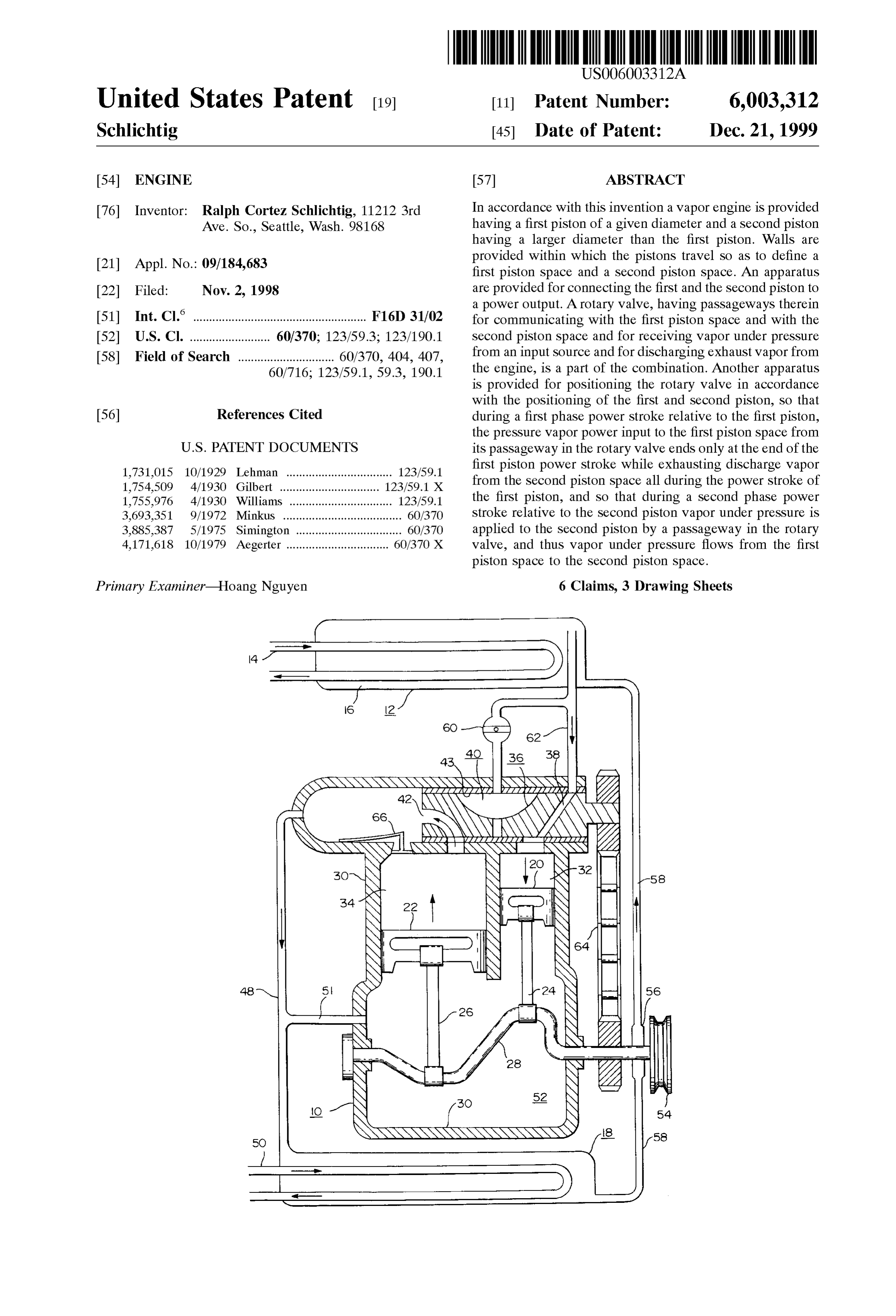
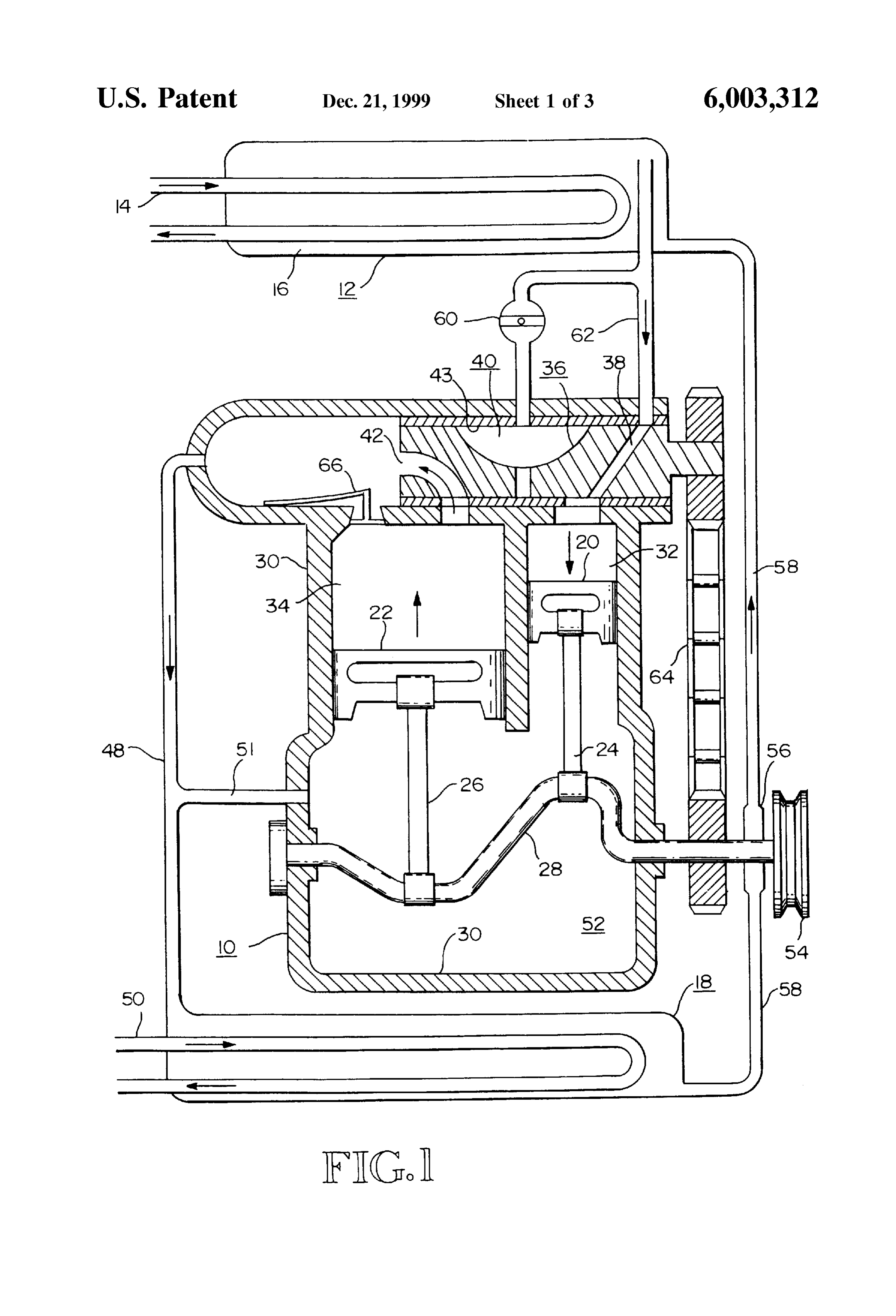
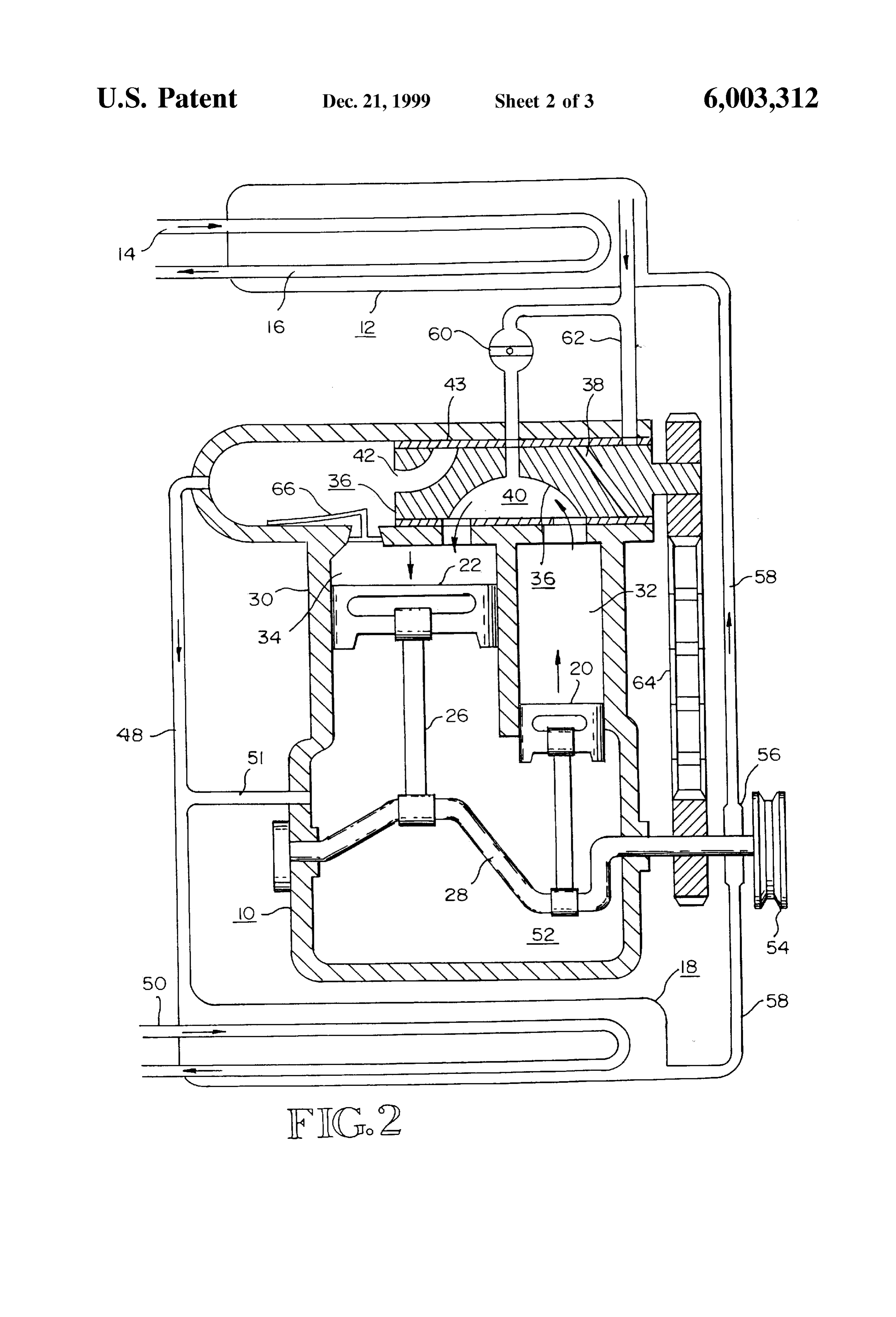
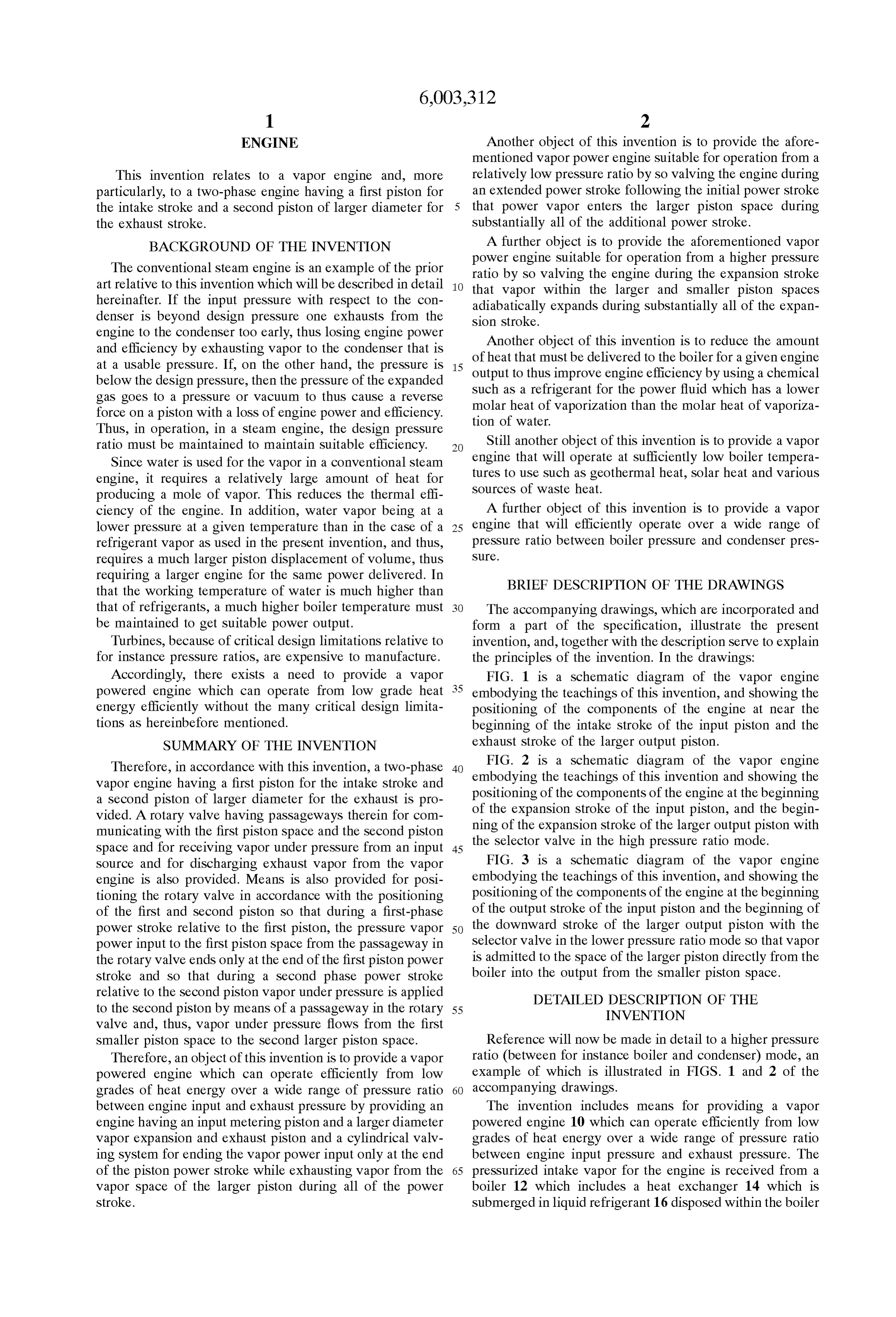
requiring a larger engine for the Same power delivered. In BRIEF DESCRIPTION OF THE DRAWINGS that the working temperature of water is much higher than that of refrigerants, a much higher boiler temperature must The accompanying drawings, which are incorporated and be maintained to get Suitable power output. form a part of the Specification, illustrate the present Turbines, because of critical design limitations relative to invention, and, together with the description Serve to explain for instance preSSure ratios, are expensive to manufacture. the principles of the invention. In the drawings: Accordingly, there exists a need to provide a vapor FIG. 1 is a Schematic diagram of the vapor engine powered engine which can operate from low grade heat 35 embodying the teachings of this invention, and showing the energy efficiently without the many critical design limita positioning of the components of the engine at near the tions as hereinbefore mentioned. beginning of the intake Stroke of the input piston and the SUMMARY OF THE INVENTION exhaust Stroke of the larger output piston.
Therefore, in accordance with this invention, a two-phase 40 FIG. 2 isthea teachings
Schematic diagram of the vapor engine
Vapor engine having a first piston for the intake Stroke and embodying of this invention and showing the a Second piston of larger diameter for the exhaust is pro of the expansion Stroke of theofinput positioning of the components the engine at the beginning piston, and the begin
Vided. A rotary valve having passageways therein for com ning of the expansion Stroke of the larger output piston with municating with the first piston Space and the Second piston
Space and for receiving vapor under pressure from an input 45 the Selector valve in the high pressure ratio mode. Source and for discharging exhaust vapor from the vapor FIG. 3 is a Schematic diagram of the vapor engine engine is also provided. Means is also provided for posi embodying the teachings of this invention, and showing the tioning the rotary valve in accordance with the positioning positioning of the components of the engine at the beginning of the first and Second piston So that during a first-phase of the output Stroke of the input piston and the beginning of power Stroke relative to the first piston, the pressure vapor 50 the downward Stroke of the larger output piston with the power input to the first piston Space from the passageway in Selector valve in the lower pressure ratio mode So that vapor the rotary valve ends only at the end of the first piston power is admitted to the Space of the larger piston directly from the Stroke and So that during a Second phase power Stroke boiler into the output from the Smaller piston Space. relative to the Second piston Vapor under preSSure is applied DETAILED DESCRIPTION OF THE to the Second piston by means of a passageway in the rotary 55 INVENTION Valve and, thus, vapor under preSSure flows from the first
Smaller piston Space to the Second larger piston Space. Reference will now be made in detail to a higher pressure Therefore, an object of this invention is to provide a vapor ratio (between for instance boiler and condenser) mode, an powered engine which can operate efficiently from low example of which is illustrated in FIGS. 1 and 2 of the grades of heat energy over a wide range of pressure ratio 60 accompanying drawings.
between engine input and exhaust pressure by providing an The invention includes means for providing a vapor engine having an input metering piston and a larger diameter powered engine 10 which can operate efficiently from low Vapor expansion and exhaust piston and a cylindrical valv grades of heat energy over a wide range of pressure ratio ing System for ending the vapor power input only at the end between engine input preSSure and exhaust pressure. The of the piston power Stroke while exhausting vapor from the 65 preSSurized intake vapor for the engine is received from a Vapor Space of the larger piston during all of the power boiler 12 which includes a heat exchanger 14 which is Stroke. submerged in liquid refrigerant 16 disposed within the boiler
Page 6
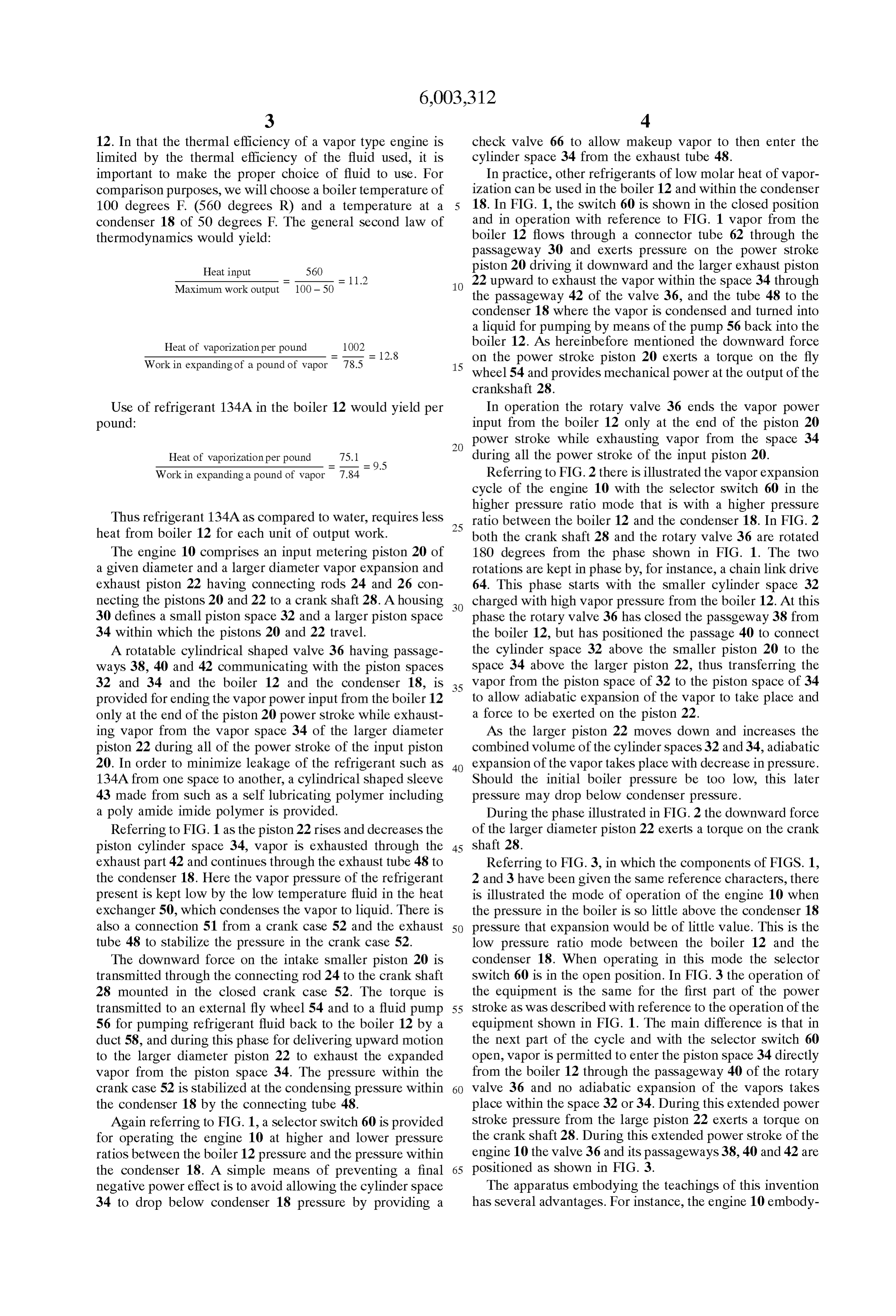
12. In that the thermal efficiency of a vapor type engine is check valve 66 to allow makeup vapor to then enter the limited by the thermal efficiency of the fluid used, it is cylinder space 34 from the exhaust tube 48. important to make the proper choice of fluid to use. For In practice, other refrigerants of low molar heat of vapor comparison purposes, we will choose a boiler temperature of ization can be used in the boiler 12 and within the condenser 100 degrees F. (560 degrees R) and a temperature at a 5 18. In FIG. 1, the Switch 60 is shown in the closed position condenser 18 of 50 degrees F. The general second law of and in operation with reference to FIG. 1 vapor from the thermodynamics would yield: boiler 12 flows through a connector tube 62 through the passageway 30 and exerts pressure on the power Stroke
Heat input 560 piston 20 driving it downward and the larger exhaust piston Maximum work output 100-50 22 upward to exhaust the vapor within the Space 34 through the passageway 42 of the valve 36, and the tube 48 to the condenser 18 where the vapor is condensed and turned into a liquid for pumping by means of the pump 56 back into the
Heat of vaporization per pound boiler 12. As hereinbefore mentioned the downward force Work in expanding of a pound of vapor
on the power Stroke piston 20 exerts a torque on the fly wheel 54 and provides mechanical power at the output of the crankshaft 28.
Use of refrigerant 134A in the boiler 12 would yield per In operation the rotary valve 36 ends the vapor power pound: input from the boiler 12 only at the end of the piston 20 power Stroke while exhausting vapor from the Space 34
Heat of vaporization per pound 75.1
during all the power Stroke of the input piston 20.
Work in expanding a pound of vapor 7.84 Referring to FIG. 2 there is illustrated the vapor expansion cycle of the engine 10 with the selector Switch 60 in the higher pressure ratio mode that is with a higher preSSure
Thus refrigerant 134A as compared to water, requires leSS 25 ratio between the boiler 12 and the condenser 18. In FIG. 2 heat from boiler 12 for each unit of output work. both the crank shaft 28 and the rotary valve 36 are rotated The engine 10 comprises an input metering piston 20 of 180 degrees from the phase shown in FIG. 1. The two a given diameter and a larger diameter vapor expansion and rotations are kept in phase by, for instance, a chain link drive exhaust piston 22 having connecting rods 24 and 26 con 64. This phase starts with the smaller cylinder space 32 necting the pistons 20 and 22 to a crank shaft 28. A housing charged with high vapor pressure from the boiler 12. At this 30 defines a Small piston Space 32 and a larger piston Space phase the rotary valve 36 has closed the passgeway 38 from 34 within which the pistons 20 and 22 travel. the boiler 12, but has positioned the passage 40 to connect A rotatable cylindrical shaped valve 36 having passage the cylinder space 32 above the smaller piston 20 to the ways 38, 40 and 42 communicating with the piston spaces Space 34 above the larger piston 22, thus transferring the 32 and 34 and the boiler 12 and the condenser 18, is 35 Vapor from the piston Space of 32 to the piston Space of 34 provided for ending the vapor power input from the boiler 12 to allow adiabatic expansion of the vapor to take place and only at the end of the piston 20 power stroke while exhaust a force to be exerted on the piston 22. ing vapor from the vapor space 34 of the larger diameter AS the larger piston 22 moves down and increases the piston 22 during all of the power Stroke of the input piston combined volume of the cylinder spaces 32 and 34, adiabatic 20. In order to minimize leakage of the refrigerant Such as 40 expansion of the vapor takes place with decrease in pressure. 134A from one space to another, a cylindrical shaped sleeve Should the initial boiler pressure be too low, this later 43 made from Such as a Self lubricating polymer including preSSure may drop below condenser pressure. a poly amide imide polymer is provided. During the phase illustrated in FIG. 2 the downward force Referring to FIG. 1 as the piston 22 rises and decreases the of the larger diameter piston 22 exerts a torque on the crank piston cylinder Space 34, vapor is exhausted through the 45 shaft 28.
exhaust part 42 and continues through the exhaust tube 48 to Referring to FIG. 3, in which the components of FIGS. 1, the condenser 18. Here the vapor pressure of the refrigerant 2 and 3 have been given the same reference characters, there present is kept low by the low temperature fluid in the heat is illustrated the mode of operation of the engine 10 when exchanger 50, which condenses the vapor to liquid. There is the pressure in the boiler is so little above the condenser 18 also a connection 51 from a crank case 52 and the exhaust 50 pressure that expansion would be of little value. This is the tube 48 to stabilize the pressure in the crank case 52. low pressure ratio mode between the boiler 12 and the The downward force on the intake Smaller piston 20 is condenser 18. When operating in this mode the selector transmitted through the connecting rod 24 to the crank shaft Switch 60 is in the open position. In FIG. 3 the operation of 28 mounted in the closed crank case 52. The torque is the equipment is the same for the first part of the power transmitted to an external fly wheel 54 and to a fluid pump 55 Stroke as was described with reference to the operation of the 56 for pumping refrigerant fluid back to the boiler 12 by a equipment shown in FIG. 1. The main difference is that in duct 58, and during this phase for delivering upward motion the next part of the cycle and with the selector Switch 60 to the larger diameter piston 22 to exhaust the expanded open, vapor is permitted to enter the piston Space 34 directly vapor from the piston space 34. The pressure within the from the boiler 12 through the passageway 40 of the rotary crank case 52 is Stabilized at the condensing pressure within 60 Valve 36 and no adiabatic expansion of the vapors takes the condenser 18 by the connecting tube 48. place within the space 32 or 34. During this extended power Again referring to FIG. 1, a selector Switch 60 is provided Stroke preSSure from the large piston 22 exerts a torque on for operating the engine 10 at higher and lower pressure the crank shaft 28. During this extended power stroke of the ratios between the boiler 12 pressure and the pressure within engine 10 the valve 36 and its passageways 38, 40 and 42 are the condenser 18. A simple means of preventing a final 65 positioned as shown in FIG. 3.
negative power effect is to avoid allowing the cylinder Space The apparatus embodying the teachings of this invention 34 to drop below condenser 18 pressure by providing a has Several advantages. For instance, the engine 10 embody
Page 7
S 6 ing the teachings of this invention can operate from low than Said first piston, walls within which said first piston and grades of heat energy found all over the World, Such as Solar, Said Second piston travel So as to define a first piston Space geothermal, and ocean temperature differences, and can and a Second piston Space; means connecting Said first piston operate at a necessary efficiency. and Said Second piston to a mechanical output to provide a Also, the engine 10 is relatively simple, and, thus, initial power output, a condenser for receiving and condensing first costs are kept to a minimum. exhaust vapor; a rotary valve having passageways therein Further, the engine 10 can operate from a wide range of for communicating with the first piston Space and with the temperature differences between, for instance, the boiler and Second piston Space and for receiving the preSSure vapor condenser. from Said boiler and for discharging exhaust vapor to Said Furthermore, the engine is a Safe device with low main condenser; means for positioning Said rotary valve in accor tenance and replacements costs. dance with the positioning of Said first piston and Said I claim as my invention: Second piston So that during a first phase power Stroke 1. In a vapor engine, the combination comprising, a first relative to Said first piston the pressurized vapor power input piston of a given diameter; a Second piston having a larger 15 to the first piston Space from the passageway in Said rotary diameter than the first piston; walls within which said first Valve ends only at the end of Said first piston power Stroke piston and Said Second piston travel So as to define a first while exhausting discharge vapor from the Second piston piston Space and a Second piston Space; means connecting Space to Said condenser all during the power Stroke of Said Said first piston and Said Second piston to a mechanical first piston, and So that during a Second phase power Stroke output to provide a power output; a rotary valve, having relative to Said Second piston Vapor under pressure is applied passageways therein for communicating with the first piston to Said Second piston by means of a passageway in Said Space and with the Second piston Space and for receiving rotary valve and thus pressurized vapor flows from the first preSSure vapor from an input Source and for discharging piston Space to the Second piston Space.
exhaust vapor from the vapor engine, means for positioning 4. The combination of claim3 in which the boiler contains Said rotary valve in accordance with the positioning of Said 25 aa refrigerant with low molar heat of vaporization producing pressurized vapor of Such refrigerant.
first piston and Said Second piston So that during a first phase 5. The combination of claim 3 in which a control means power Stroke relative to Said first piston, the pressure vapor power input to the first piston Space from the passageways is dispersed between Said boiler and Said rotary valve to in Said rotary valve ends only at the end of Said first piston control the flow of pressured vapor from said boiler through power Stroke while exhausting discharge vapor from the Said rotary valve to the piston Space of Said Second piston. Second piston Space all during the power Stroke of Said first 6. The combination of claim 5 in which said control piston, and So that during a Second phase power Stroke means has an open and a closed position and while in the relative to Said Second piston Vapor under pressure is applied open position pressurized vapor flows from Said boiler to Said Second piston by means of a passageway in Said through the passageway of said rotary valve to the piston rotary valve and, thus, under pressure, vapor flows from the 35 Space of Said Second piston So as to exert a force on Said first piston Space to the Second piston Space. Second piston during the Second phase power Stroke relative 2. The vapor engine of claim 1 in which the rotary valve to Said Second piston and while in the closed position and is disposed in and travels within a cylindrical Sleeve made during the Second phase power Stroke relative to Said Second from a Self lubricating polymer including poly amide imide piston adiabatic expansion of the vapor within the piston polymers. 40
Space of Said first piston causes a force to be exerted on Said 3. In a vapor power System, the combination comprising, Second piston.
a boiler for producing a pressurized vapor; a first piston of a given diameter; a Second piston having a larger diameter
Provenance
- Collection
- Cited prior art
- Original PDF
- patentimages.storage.googleapis.com →
- Filed
- 1998-11-02
- Pages
- 7
- Method
- pdftotext (the PDF's own text layer) + pdftoppm 300dpi page scans
- Source
- Google Patents bibliographic record
- Granted
- 1999-12-21
- Inventors
- Ralph Cortez Schlichtig
- Transcribed from
- patentimages.storage.googleapis.com →