patent · US6015133
Fuel vapor managment valve
18 January 2000
Page 1 — bibliographic record
United States Patent (19) 11 Patent Number: 6,015,133 DeLand (45) Date of Patent: Jan. 18, 2000 54 FUEL VAPOR MANAGMENT VALVE 5,878,725 3/1999 Osterbrink ....................... 251/30.01 X 75 I tor: Daniele L. DeLand, Primary Examiner Kevin Lee
LaV1Son, Mich.
Mic Attorney, Agent, or Firm-Roger A. Johnston 73 Assignee: Eaton Corporation, Cleveland, Ohio 57 ABSTRACT 21 Appl. No.: 09/300,286 An electrically controlled Vacuum operated fuel vapor can ister purge valve having a regulator valve Subassembly with 22 Filed: Apr. 27, 1999 a vacuum Signal chamber on one Side of a pressure respon 51 Int. Cl." ............................ F16K 31/40; F02M 33/02 is girls". Itrise,S.'" o s - - - - - - - - h - - - - - - - - - - - - - 251/30.01; S5 251/118 Vapor outlet passage for connection to an engine inlet. The 58 Field of Search .............................. 251/3. Vacuum Signal chamber has a vacuum signal connection port /45, and a receSS or well with an atmospheric vent port and resiliently deflectable locking tab. A Solenoid operated atmo 56) References Cited spheric bleed valve has a boss with a restrictor outlet which
5,277,167 1/1994 DeLand etal 123/518 controlling vent flow into the vacuum signal chamber. The 21 C and el all. . . . . . . . . . . . . . . . . . . . . . . . . . restrictor limits atmospheric bleed flow to attenuate the : E. R al - - - - - - - "if, R effects of Sudden changes in the vacuum signal.
5,855,355 1/1999 Grunert et al. ..................... 251/118 X 7 Claims, 3 Drawing Sheets
NTAKE
2. -- MANFOLD
arvae
SNZ.6% 24 28 4Nan SSN
S sfin
8 NansS4 as
Page 2
Drawing sheet — no readable text.
Page 3
Drawing sheet — no readable text.
Page 4
Drawing sheet — no readable text.
Page 5
FUEL WAPOR MANAGMENT WALVE assemble and which can accommodate numerous different flow conditions for different engine applications without
CROSS-REFERENCE TO RELATED requiring redesign or retooling of the valve assembly. APPLICATIONS It is a further object of the present invention to provide an Not Applicable electrically operated fluid preSSure actuated fuel vapor man agement valve which can utilize a single electrically oper
STATEMENT REGARDING FEDERALLY ated vent valve for numerous different flow requirements of SPONSORED RESEARCH OR DEVELOPMENT various different engines without the need for significant modifications of the valve.
Not Applicable 1O
It is a further object of the present invention to provide a
MICROFICHEAPPENDIX
Solenoid operated vent valve for controlling atmospheric bleed flow to the vacuum Signal pressure chamber of a vapor
Not Applicable management valve for controlling the differential preSSure
acroSS a power diaphragm for moving the fuel vapor purge
BACKGROUND OF THE INVENTION Valve and controlling flow from the canister to the engine inlet.
The present invention relates to valves of the type The present invention provides a fuel vapor canister purge employed for controlling purging of fuel vapor Stored in a Valve which employs a vacuum signal actuated diaphragm canister connected to receive vapors from a vehicle fuel tank operated and for introducing the vapor purge flow into the inlet of the ister to anregulator engine valve for controlling flow from the can inlet. The valve of the present invention vehicle engine. Such valves are known in the art and has the regulator housing typically utilize a vacuum signal Such as from the engine receSS or well which has a provided with a vent port in a manifold, to control the preSSure on one side of a power spheric bleed valve (EVR) quick-connectedventtherein. Solenoid operated or atmo diaphragm employed to control the movement of a Valving restrictor is provided upstream of the vent port in theA member or obturator with respect to a valve Seat or port for 25 regulator housing and preferably in the outlet of the EVR for controlling flow of the vapor between the canister and the controlling flow to the vent port in the regulator housing and engine inlet. In order to provide electrical control of the
Vapor purge flow to the engine inlet where the engine particularly to prevent or delay loSS of vacuum in the Signal pressure chamber. Alternatively the EVR may have the operation is controlled by electrically actuated fuel injectors restrictor located at its inlet. The restrictor in the outlet of the an electrically operated valve is employed to control atmo Solenoid operated vent valve or EVR may be easily changed Spheric bleed to a vacuum Signal chamber on one side of the during manufacture; and, the flow characteristics of the vent power diaphragm.
Valve thereby changed to accommodate different engine
However, vapor management valves of the aforesaid type applications. The design and Structure of the regulator valve employing a vacuum generated control Signal for the power thus may be common to many different applications. diaphragm are effected by changes in the engine manifold 35 The valve arrangement of the present invention enables Vacuum. When the engine throttle is closed, from an engine use of a common regulator valve for mounting on engines loaded condition, a Strong manifold vacuum is applied with the different purge flow requirements to be accommo through the regulator valve outlet to the underside of the dated by merely changing the outlet port size in the Solenoid power diaphragm. The restrictor in the vacuum Signal port vent valve (EVR) which is preferably quick-connected to the causes a lag in the corresponding vacuum level being 40 regulator housing.
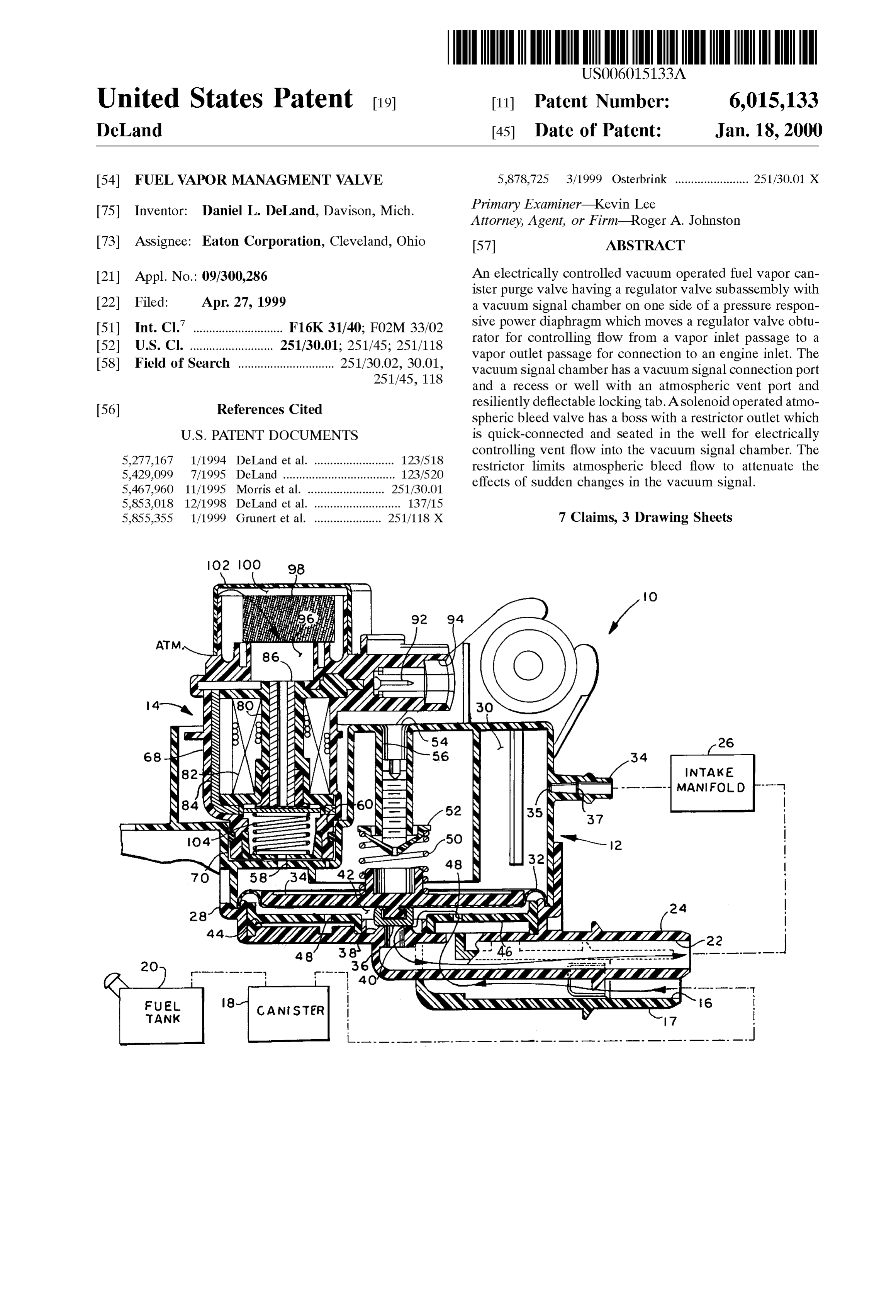
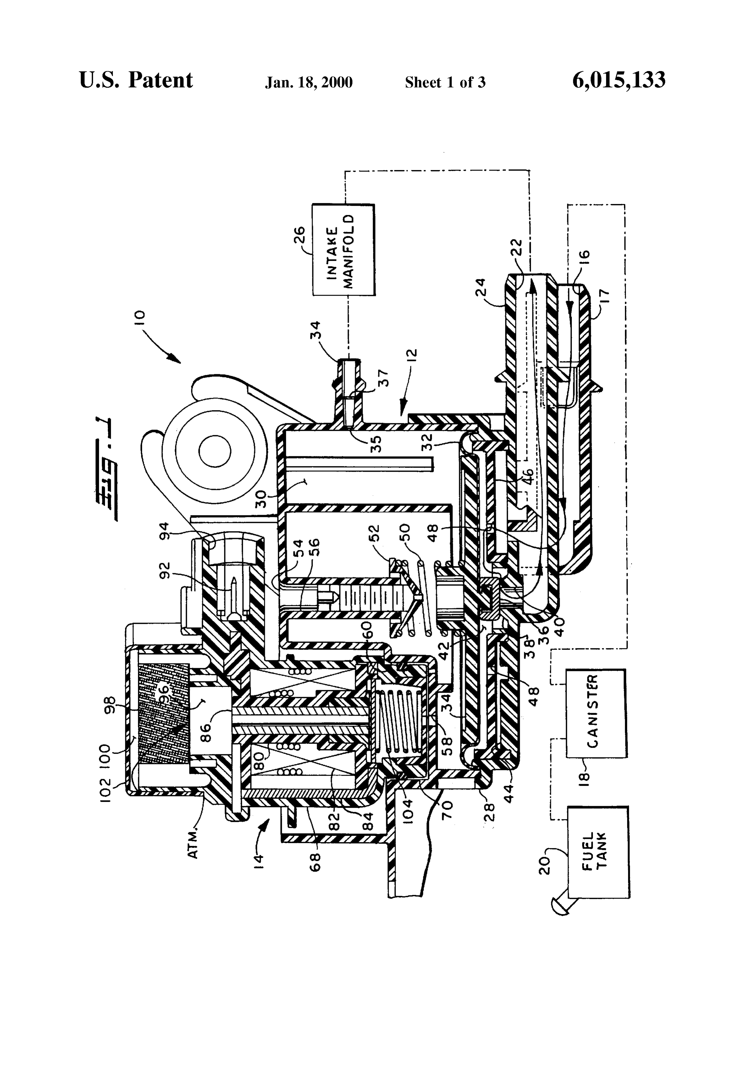
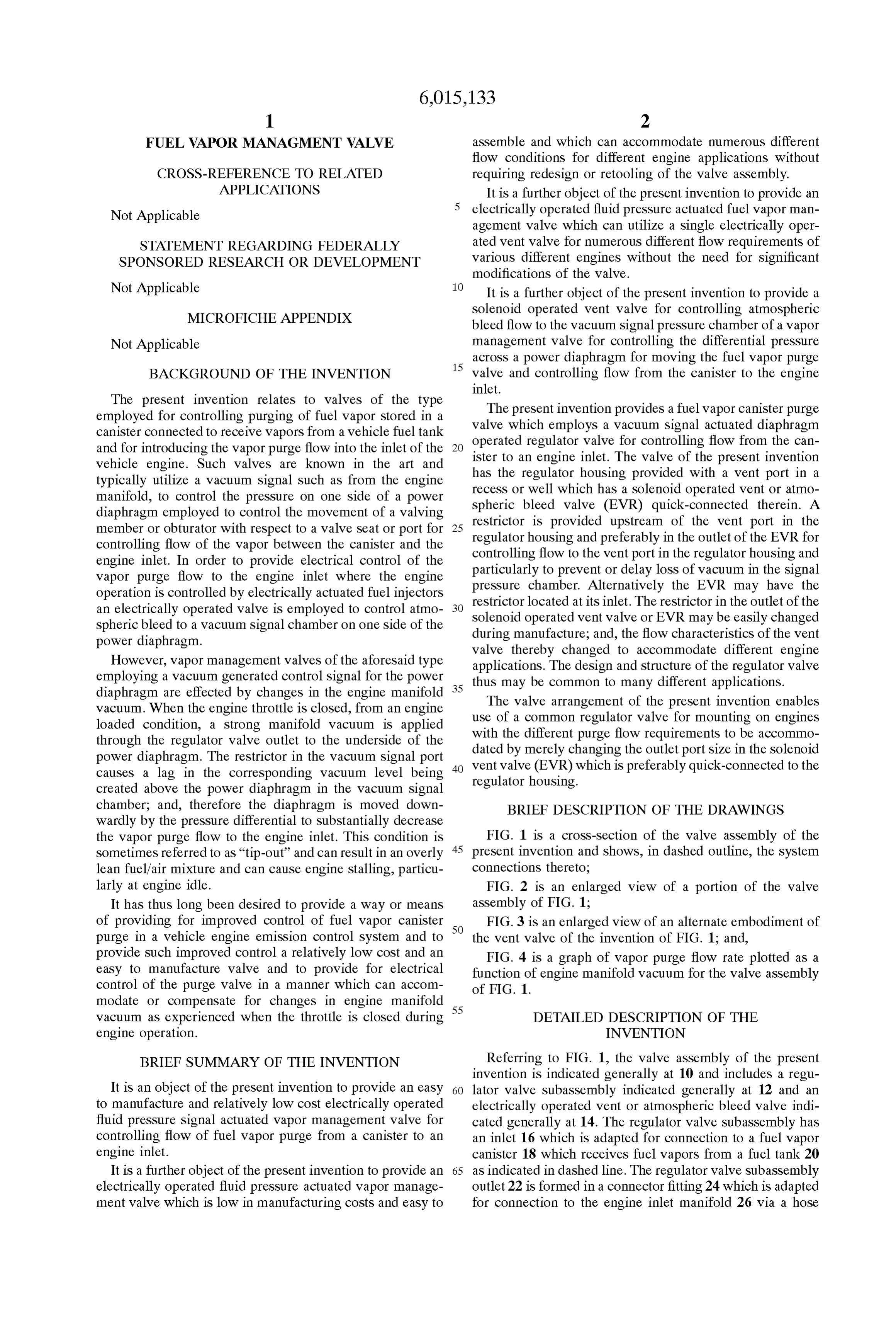
created above the power diaphragm in the vacuum signal chamber; and, therefore the diaphragm is moved down BRIEF DESCRIPTION OF THE DRAWINGS wardly by the pressure differential to substantially decrease the vapor purge flow to the engine inlet. This condition is FIG. 1 is a cross-section of the valve assembly of the Sometimes referred to as "tip-out' and can result in an overly 45 present invention and shows, in dashed outline, the System lean fuel/air mixture and can cause engine Stalling, particu connections thereto;
larly at engine idle. FIG. 2 is an enlarged view of a portion of the valve It has thus long been desired to provide a way or means assembly of FIG. 1;
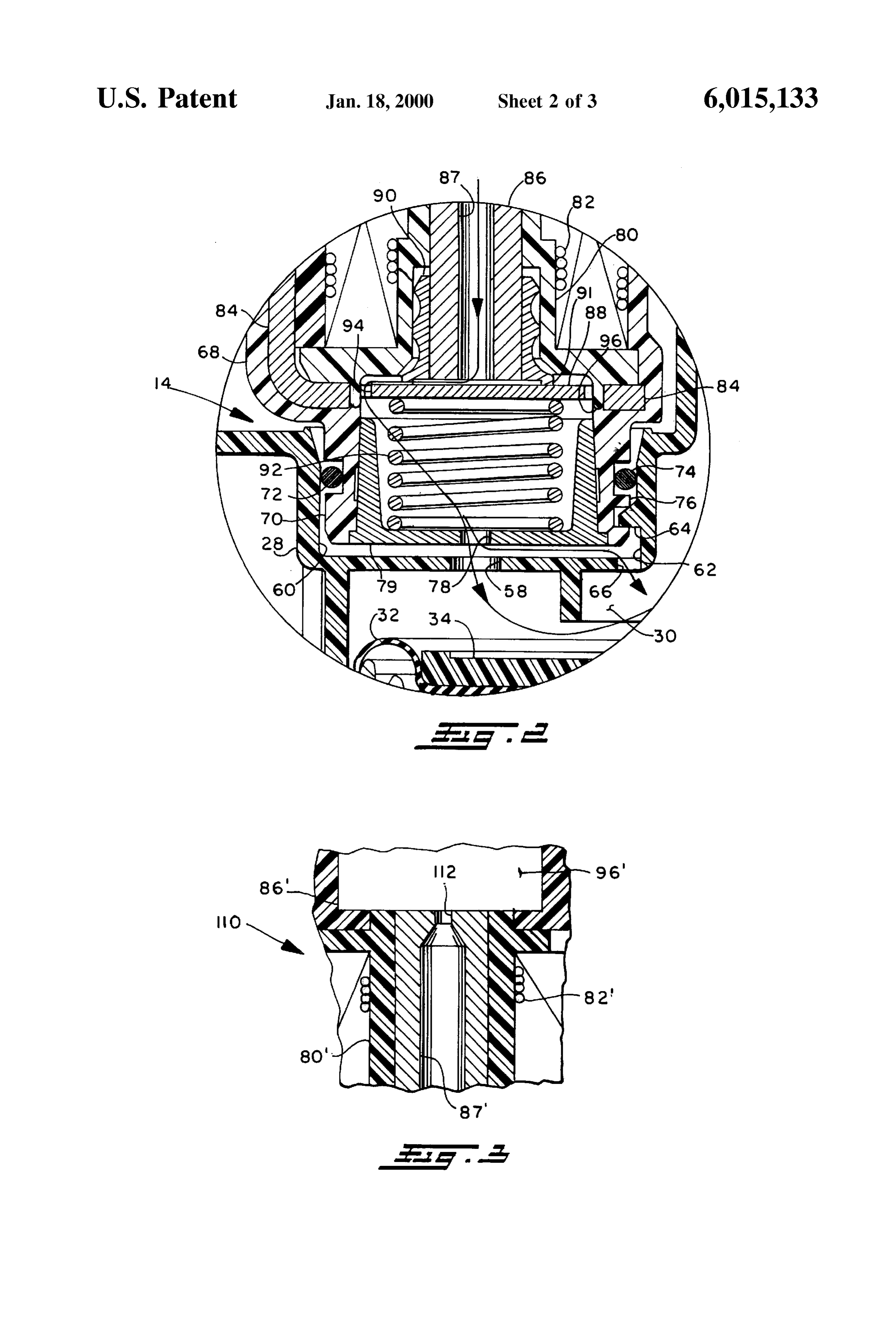
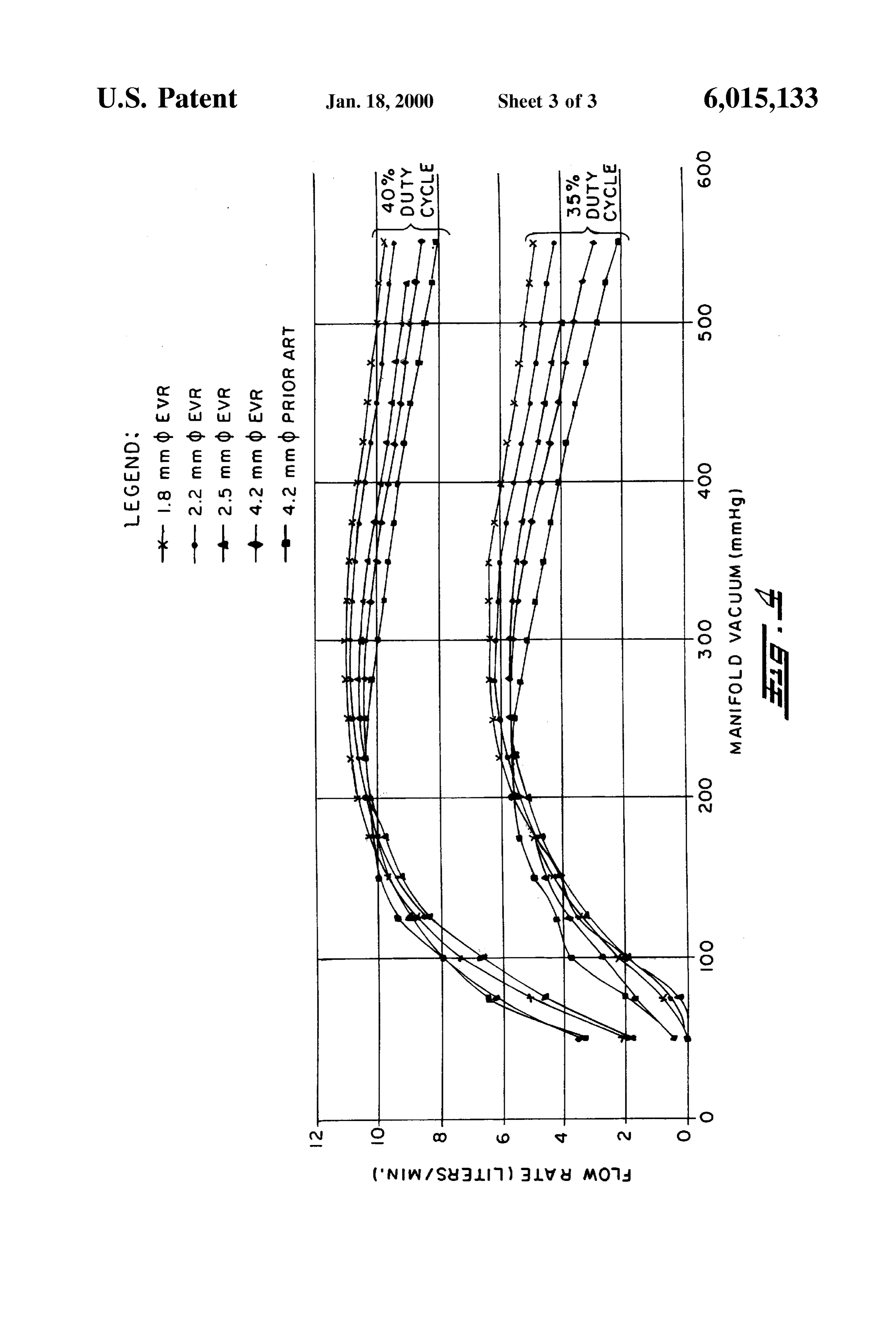
of providing for improved control of fuel vapor canister 50 FIG. 3 is an enlarged view of an alternate embodiment of purge in a vehicle engine emission control System and to the vent valve of the invention of FIG. 1; and, provide Such improved control a relatively low cost and an FIG. 4 is a graph of vapor purge flow rate plotted as a easy to manufacture valve and to provide for electrical function of engine manifold vacuum for the valve assembly control of the purge valve in a manner which can accom of FIG. 1.
modate or compensate for changes in engine manifold
Vacuum as experienced when the throttle is closed during 55 DETAILED DESCRIPTION OF THE engine operation. INVENTION BRIEF SUMMARY OF THE INVENTION Referring to FIG. 1, the valve assembly of the present invention is indicated generally at 10 and includes a regu
It is an object of the present invention to provide an easy 60 lator valve Subassembly indicated generally at 12 and an to manufacture and relatively low cost electrically operated electrically operated vent or atmospheric bleed Valve indi fluid preSSure Signal actuated vapor management valve for cated generally at 14. The regulator valve Subassembly has controlling flow of fuel vapor purge from a canister to an an inlet 16 which is adapted for connection to a fuel Vapor engine inlet. canister 18 which receives fuel vapors from a fuel tank 20 It is a further object of the present invention to provide an 65 as indicated in dashed line. The regulator valve Subassembly electrically operated fluid preSSure actuated vapor manage outlet 22 is formed in a connector fitting 24 which is adapted ment valve which is low in manufacturing costs and easy to for connection to the engine inlet manifold 26 via a hose
Page 6
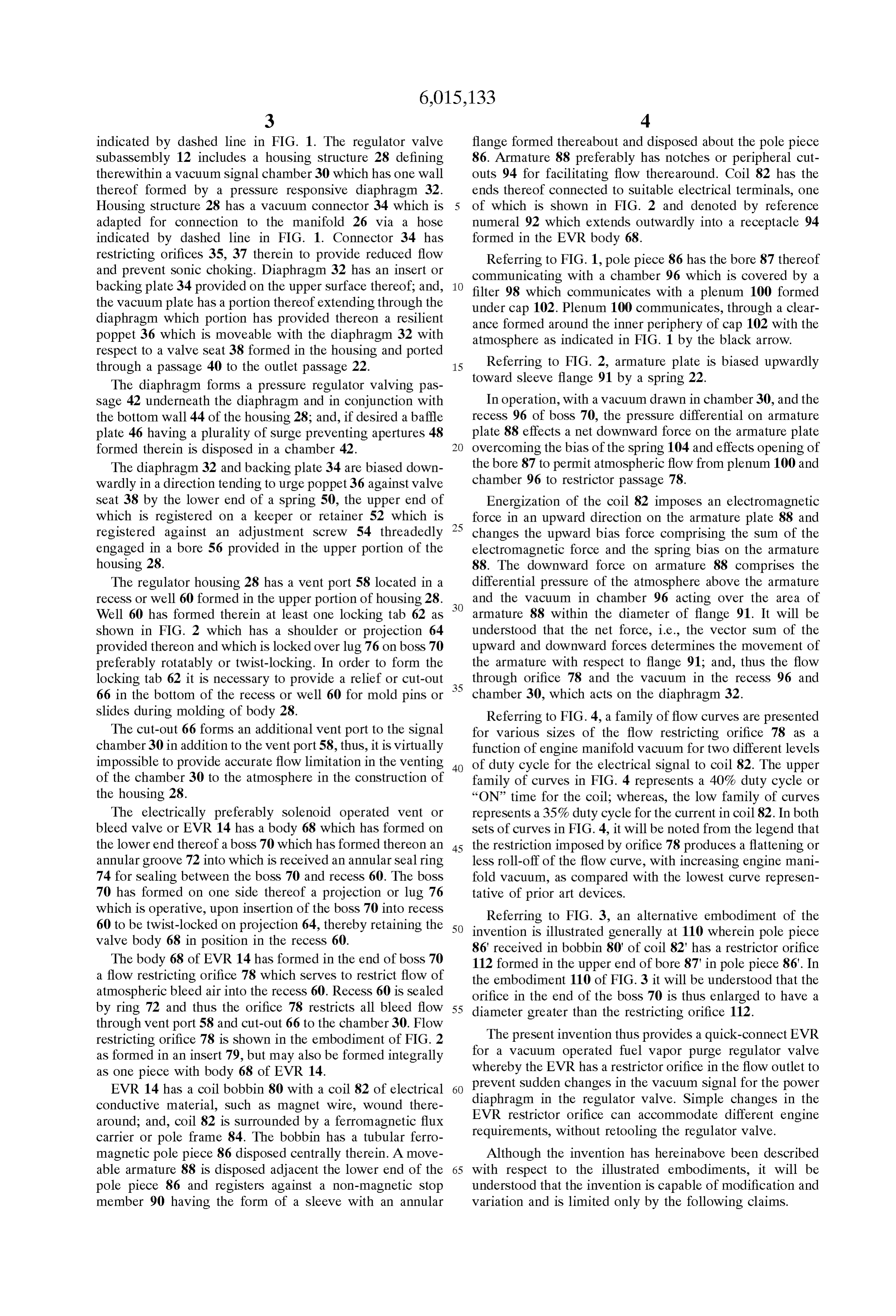
indicated by dashed line in FIG. 1. The regulator valve flange formed thereabout and disposed about the pole piece Subassembly 12 includes a housing Structure 28 defining 86. Armature 88 preferably has notches or peripheral cut therewithin a vacuum signal chamber 30 which has one wall outs 94 for facilitating flow therearound. Coil 82 has the thereof formed by a pressure responsive diaphragm 32. ends thereof connected to Suitable electrical terminals, one Housing structure 28 has a vacuum connector 34 which is of which is shown in FIG. 2 and denoted by reference adapted for connection to the manifold 26 via a hose numeral 92 which extends outwardly into a receptacle 94 indicated by dashed line in FIG. 1. Connector 34 has formed in the EVR body 68.
restricting orifices 35, 37 therein to provide reduced flow Referring to FIG. 1, pole piece 86 has the bore 87 thereof and prevent Sonic choking. Diaphragm 32 has an insert or communicating with a chamber 96 which is covered by a backing plate 34 provided on the upper Surface thereof; and, filter 98 which communicates with a plenum 100 formed the vacuum plate has a portion thereof extending through the under cap 102. Plenum 100 communicates, through a clear diaphragm which portion has provided thereon a resilient ance formed around the inner periphery of cap 102 with the poppet 36 which is moveable with the diaphragm 32 with atmosphere as indicated in FIG. 1 by the black arrow. respect to a valve Seat 38 formed in the housing and ported through a passage 40 to the outlet passage 22. 15 Referring to FIG. 2, armature plate is biased upwardly The diaphragm forms a pressure regulator Valving pas toward sleeve flange 91 by a spring 22.
Sage 42 underneath the diaphragm and in conjunction with In operation, with a vacuum drawn in chamber 30, and the the bottom wall 44 of the housing 28; and, if desired a baffle recess 96 of boss 70, the pressure differential on armature plate 46 having a plurality of Surge preventing apertures 48 plate 88 effects a net downward force on the armature plate formed therein is disposed in a chamber 42. overcoming the bias of the Spring 104 and effects opening of The diaphragm 32 and backing plate 34 are biased down the bore 87 to permit atmospheric flow from plenum 100 and Wardly in a direction tending to urge poppet 36 against Valve chamber 96 to restrictor passage 78. seat 38 by the lower end of a spring 50, the upper end of Energization of the coil 82 imposes an electromagnetic which is registered on a keeper or retainer 52 which is 25 force in an upward direction on the armature plate 88 and registered against an adjustment Screw 54 threadedly changes the upward bias force comprising the Sum of the engaged in a bore 56 provided in the upper portion of the electromagnetic force and the Spring bias on the armature housing 28. 88. The downward force on armature 88 comprises the The regulator housing 28 has a vent port 58 located in a differential pressure of the atmosphere above the armature recess or well 60 formed in the upper portion of housing 28. and the vacuum in chamber 96 acting over the area of Well 60 has formed therein at least one locking tab 62 as armature 88 within the diameter of flange 91. It will be shown in FIG. 2 which has a shoulder or projection 64 understood that the net force, i.e., the vector Sum of the provided thereon and which is locked over lug 76 on boss 70 upward and downward forces determines the movement of preferably rotatably or twist-locking. In order to form the the armature with respect to flange 91; and, thus the flow locking tab 62 it is necessary to provide a relief or cut-out 35 through orifice 78 and the vacuum in the recess 96 and 66 in the bottom of the recess or well 60 for mold pins or chamber 30, which acts on the diaphragm 32. slides during molding of body 28. Referring to FIG. 4, a family of flow curves are presented The cut-out 66 forms an additional vent port to the signal for various sizes of the flow restricting orifice 78 as a chamber 30 in addition to the vent port 58, thus, it is virtually function of engine manifold vacuum for two different levels impossible to provide accurate flow limitation in the venting 40 of duty cycle for the electrical signal to coil 82. The upper of the chamber 30 to the atmosphere in the construction of family of curves in FIG. 4 represents a 40% duty cycle or the housing 28. “ON” time for the coil; whereas, the low family of curves The electrically preferably solenoid operated vent or represents a 35% duty cycle for the current in coil 82. In both bleed valve or EVR 14 has a body 68 which has formed on sets of curves in FIG. 4, it will be noted from the legend that the lower end thereof a boss 70 which has formed thereon an 45 the restriction imposed by orifice 78 produces a flattening or annular groove 72 into which is received an annular Seal ring less roll-off of the flow curve, with increasing engine mani 74 for sealing between the boss 70 and recess 60. The boss fold vacuum, as compared with the lowest curve represen 70 has formed on one side thereof a projection or lug 76 tative of prior art devices.
which is operative, upon insertion of the boss 70 into recess Referring to FIG. 3, an alternative embodiment of the 60 to be twist-locked on projection 64, thereby retaining the 50 invention is illustrated generally at 110 wherein pole piece valve body 68 in position in the recess 60. 86 received in bobbin 80' of coil 82" has a restrictor orifice The body 68 of EVR 14 has formed in the end of boss 70 112 formed in the upper end of bore 87 in pole piece 86'. In a flow restricting orifice 78 which serves to restrict flow of the embodiment 110 of FIG. 3 it will be understood that the atmospheric bleed air into the recess 60. Recess 60 is sealed orifice in the end of the boss 70 is thus enlarged to have a by ring 72 and thus the orifice 78 restricts all bleed flow 55 diameter greater than the restricting orifice 112. through vent port 58 and cut-out 66 to the chamber 30. Flow restricting orifice 78 is shown in the embodiment of FIG. 2 The present invention thus provides a quick-connect EVR as formed in an insert 79, but may also be formed integrally for a vacuum operated fuel vapor purge regulator valve as one piece with body 68 of EVR 14. whereby the EVR has a restrictor orifice in the flow outlet to EVR 14 has a coil bobbin 80 with a coil 82 of electrical 60 prevent Sudden changes in the vacuum signal for the power conductive material, Such as magnet wire, wound there diaphragm EVR in the regulator valve. Simple changes in the restrictor orifice can accommodate different engine around; and, coil 82 is Surrounded by a ferromagnetic flux carrier or pole frame 84. The bobbin has a tubular ferro requirements, without retooling the regulator valve. magnetic pole piece 86 disposed centrally therein. A move Although the invention has hereinabove been described able armature 88 is disposed adjacent the lower end of the 65 with respect to the illustrated embodiments, it will be pole piece 86 and registers against a non-magnetic Stop understood that the invention is capable of modification and member 90 having the form of a sleeve with an annular variation and is limited only by the following claims.
Page 7
S 6
I claim: 4. The valve assembly defined in claim 1, wherein said 1. A fuel vapor management valve assembly comprising: housing Structure includes a receSS with Said vent port (a) housing structure defining a fluid pressure cavity and therein; and, Said EVR has said outlet port disposed in Said including a pressure responsive member operative on CCCSS.
one side thereof to define a fluid pressure Signal cham 5. A method of making a fuel vapor canister purge valve ber in Said cavity and on a side opposite Said one side comprising:
to define a flow regulating pressure chamber in Said (a) forming a regulator valve Subassembly having a cavity;
(b) said housing structure including a signal port com preSSure responsive diaphragm and moving the dia municating with Said fluid preSSure Signal chamber and phragm in response to a Signal pressure on one Side a fuel vapor inlet port and vapor outlet port commu thereof and controlling flow from a vapor inlet passage nicating with Said flow regulating pressure chamber, to a Vapor outlet passage;
wherein Said pressure responsive member is moveable (b) forming a signal pressure chamber in a housing on said in response to a pressure difference thereacroSS for 15 one side of Said diaphragm and porting Said chamber controlling flow between Said vapor outlet port and Said for connection to an engine inlet manifold and forming Vapor inlet port; a receSS in Said housing porting Said receSS to the (c) said housing structure further including a vent port in atmosphere;
Said fluid pressure Signal chamber; and (c) forming a restrictor in the outlet of an electrically (d) an electrically operated vent valve (EVR) for control operated bleed valve and quick-connecting and Sealing ling flow in Said vent port, Said vent valve having an Said outlet in Said recess, and, atmospheric inlet, an outlet and Valving member move able upon electrical energization for controlling flow (d) energizing said bleed valve and controlling atmo between said vent valve inlet and outlet, said EVR Spheric bleed flow to Said Signal pressure chamber. disposed to provide flow from the outlet thereof to said 25 6. The method defined in claim 5, wherein said step of vent port, wherein said vent valve includes a flow forming a receSS includes forming a resiliently deflectable restrictor for restricting flow to Said vent port. tab therein.
2. The valve defined in claim 1, wherein said EVR has 7. The method defined in claim 5, wherein said step of said flow restrictor in the outlet thereof. quick-connecting includes Snap locking. 3. The valve assembly defined in claim 1, wherein said
EVR has said flow restrictor provided in the inlet thereof.
Provenance
- Collection
- Cited prior art
- Original PDF
- patentimages.storage.googleapis.com →
- Filed
- 1999-04-27
- Pages
- 7
- Method
- pdftotext (the PDF's own text layer) + pdftoppm 300dpi page scans
- Source
- Google Patents bibliographic record
- Granted
- 2000-01-18
- Inventors
- Daniel L. DeLand; Eaton Corp
- Transcribed from
- patentimages.storage.googleapis.com →