patent · US6138655
Air/fuel control system and method
31 October 2000
Page 1 — bibliographic record
United States Patent (19) 11 Patent Number: 6,138,655 Kerns et al. (45) Date of Patent: *Oct. 31, 2000 54 AIR/FUEL CONTROL SYSTEMAND 58 Field of Search ..................................... 123/674, 675, METHOD 123/681, 682, 687, 698; 701/109, 114;
(75) Inventors: James Michael Kerns, Trenton;
William Edward Ortell, Saline; Xiao 56) References Cited
Wu, Canton, all of Mich. U.S. PATENT DOCUMENTS 73) Assignee: Ford Global Technologies, Inc., 5,048,493 9/1991 Orzel et al.............................. 123/698 Dearborn, Mich. 5,423.307 6/1995 Okawa et all ........................... 123/698 Notice: This patent is Subject to a terminal dis Primary Examiner Andrew M. Dolinar claimer. Attorney, Agent, or Firm John D. Russell
An air/ratio control System and method for an internal
Filed: Nov. 10, 1999 combustion engine coupled to a fuel Vapor recovery System Related U.S. Application Data Simultaneously maps a difference between a desired air/fuel ratio and a measured air/fuel ratio to fueling errors and a
Continuation of application No. 09/055,500, Apr. 6, 1998. purge vapor flow. This System and method maximizes the ability to purge the vapor recovery System while maintaining
Int. Cl. .................................................... F02D 41/14 the ability to diagnose fuel errors. U.S. Cl. .......................... 123/674; 123/681; 123/687;
73/117.3 13 Claims, 3 Drawing Sheets
FUELERROR =UEGO MAF-AF MAF 3/O
USE MODEL (ASDETERMINED FROMPREVIOUS STEP)
TO ESTIMATEFUEL FLOWERROR 3/2
EST FUEL ERROR is a2+ a1 MAF a2 k RPM
USE MODEL (ASDETERMINED FROMPREVIOUS STEP)
TO ESTMATE PURGEVOLUME 3/4
EST PURGE VOL = ave+ av1 MAF av2. RPM
CALCULATE REMAINING FUEL ERROR
EST RESFUEL = FUEL ERROR
EST FUEL ERROR - EST PURGE WOL
UPDATE MODEL 3/?
EST FUEL CORRECTION A2+ AL MAF A2 320
. RPM + A3 EST PURGE WOL
RETURN
Page 2
Drawing sheet — no readable text.
Page 3
Drawing sheet — no readable text.
Page 4
START
USEMODEL (ASDETERMINED FROM PREVIOUS STEP)
TO ESTIMATEFUEL FLOWERROR 3/2
EST FUEL ERROR = az, a k MAF a2 RPM
USE MODEL (ASDETERMINED FROMPREVIOUS STEP)
TO ESTIMATE PURGEVOLUME 3/4
EST PURGE VOL = av2+ av1 MAF + av2 k RPM
CALCULATE REMAINING FUEL ERROR
EST RESFUEL = FUEL ERROR
EST FUEL ERROR - EST PURGE VOL.
k RPM A3 k. EST PURGE VOL.
RETURN
Page 5
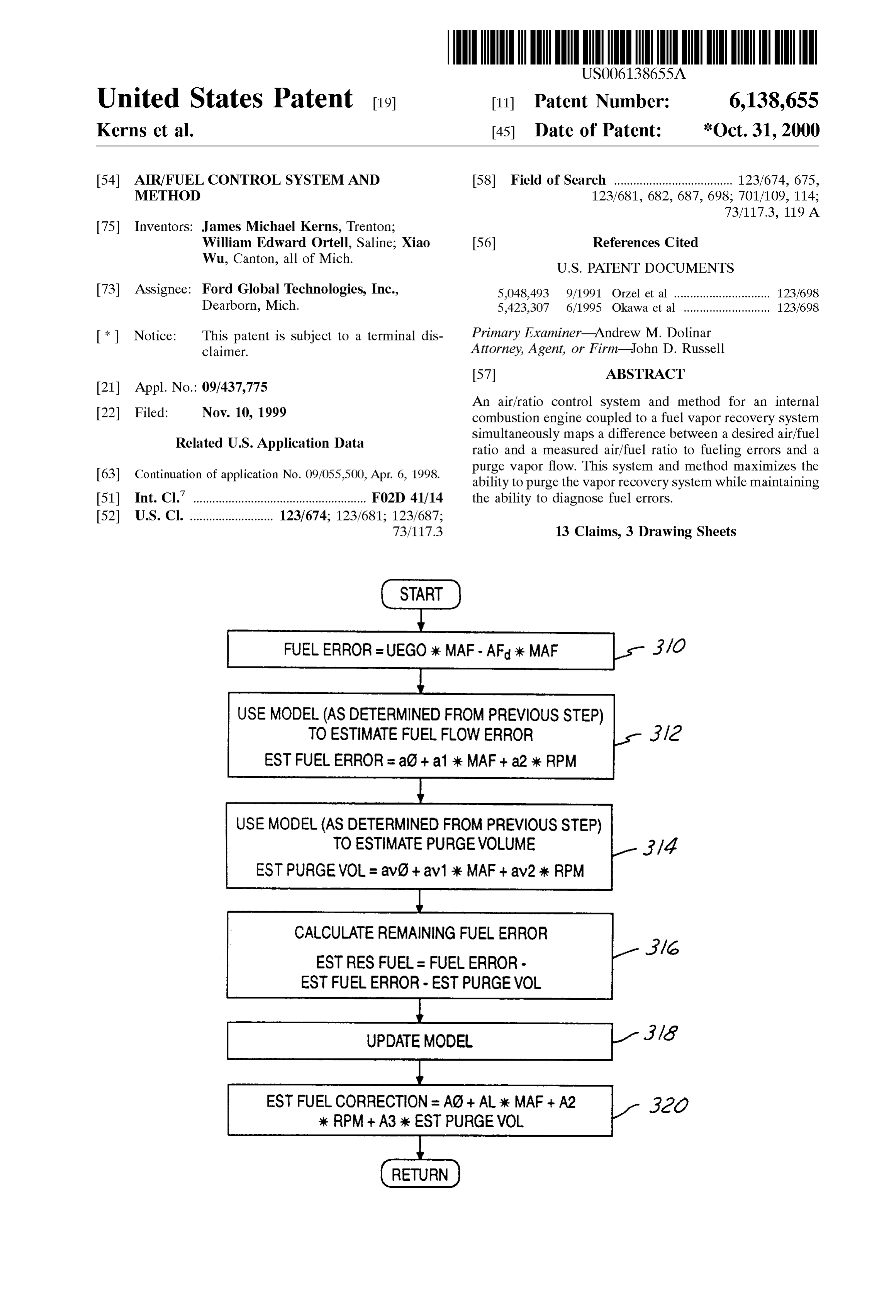
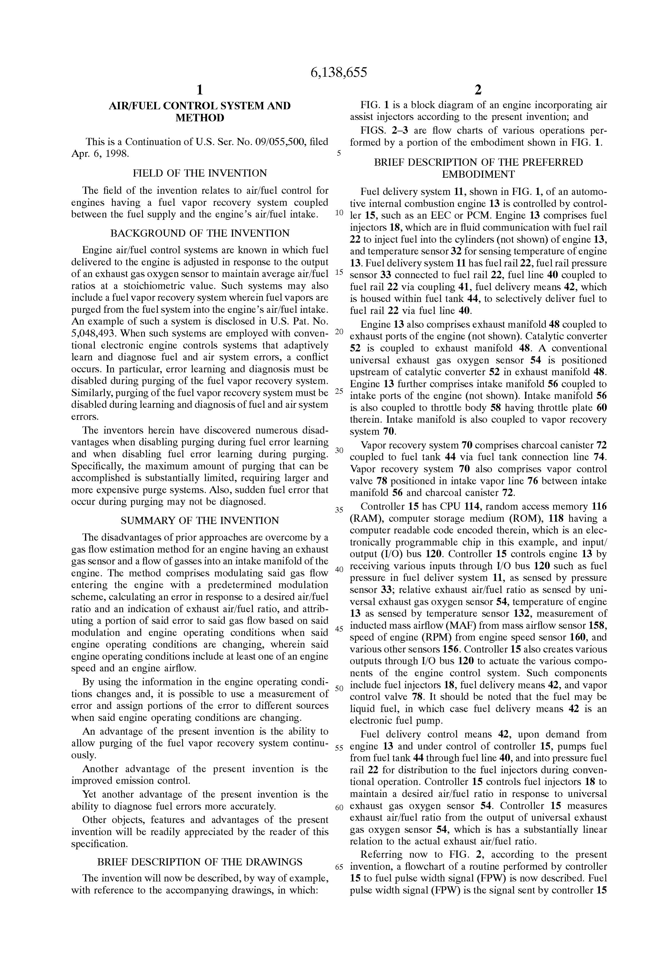
AIR/FUEL CONTROL SYSTEMAND FIG. 1 is a block diagram of an engine incorporating air METHOD assist injectors according to the present invention; and FIGS. 2-3 are flow charts of various operations per
This is a Continuation of U.S. Ser. No. 09/055,500, filed formed by a portion of the embodiment shown in FIG. 1.
BRIEF DESCRIPTION OF THE PREFERRED
FIELD OF THE INVENTION EMBODIMENT
The field of the invention relates to air/fuel control for Fuel delivery system 11, shown in FIG. 1, of an automo engines having a fuel vapor recovery System coupled tive internal combustion engine 13 is controlled by control between the fuel Supply and the engine's air/fuel intake. 1O ler 15, such as an EEC or PCM. Engine 13 comprises fuel BACKGROUND OF THE INVENTION injectors 18, which are in fluid communication with fuel rail 22 to inject fuel into the cylinders (not shown) of engine 13,
Engine air/fuel control Systems are known in which fuel and temperature Sensor 32 for Sensing temperature of engine delivered to the engine is adjusted in response to the output 13. Fuel delivery system 11 has fuel rail 22, fuel rail pressure of an exhaust gas oxygen Sensor to maintain average air/fuel 15 sensor 33 connected to fuel rail 22, fuel line 40 coupled to ratioS at a Stoichiometric value. Such Systems may also fuel rail 22 via coupling 41, fuel delivery means 42, which include a fuel vapor recovery System wherein fuel vapors are is housed within fuel tank 44, to selectively deliver fuel to purged from the fuel System into the engine's air/fuel intake. fuel rail 22 via fuel line 40.
An example of such a system is disclosed in U.S. Pat. No. Engine 13 also comprises exhaust manifold 48 coupled to 5,048,493. When such systems are employed with conven exhaust ports of the engine (not shown). Catalytic converter tional electronic engine controls Systems that adaptively 52 is coupled to exhaust manifold 48. A conventional learn and diagnose fuel and air System errors, a conflict universal exhaust gas oxygen Sensor 54 is positioned occurs. In particular, error learning and diagnosis must be upstream of catalytic converter 52 in exhaust manifold 48. disabled during purging of the fuel vapor recovery System. Engine 13 further comprises intake manifold 56 coupled to Similarly, purging of the fuel Vapor recovery System must be 25 intake ports of the engine (not shown). Intake manifold 56 disabled during learning and diagnosis of fuel and air System is also coupled to throttle body 58 having throttle plate 60 COS.
therein. Intake manifold is also coupled to vapor recovery
The inventors herein have discovered numerous disad system 70.
Vantages when disabling purging during fuel error learning Vapor recovery system 70 comprises charcoal canister 72 and when disabling fuel error learning during purging. coupled to fuel tank 44 via fuel tank connection line 74. Specifically, the maximum amount of purging that can be Vapor recovery system 70 also comprises vapor control accomplished is Substantially limited, requiring larger and valve 78 positioned in intake vapor line 76 between intake more expensive purge Systems. Also, Sudden fuel error that manifold 56 and charcoal canister 72. occur during purging may not be diagnosed. 35 Controller 15 has CPU 114, random access memory 116 SUMMARY OF THE INVENTION (RAM), computer storage medium (ROM), 118 having a The disadvantages of prior approaches are overcome by a computer readable code encoded therein, which is an elec tronically programmable chip in this example, and input/ gas flow estimation method for an engine having an exhaust output (I/O) bus 120. Controller 15 controls engine 13 by gas Sensor and a flow of gasses into an intake manifold of the 40 receiving various inputs through I/O bus 120 such as fuel engine. The method comprises modulating Said gas flow preSSure in fuel deliver System 11, as Sensed by preSSure entering the engine with a predetermined modulation Sensor 33, relative exhaust air/fuel ratio as Sensed by uni Scheme, calculating an error in response to a desired air/fuel Versal exhaust gas oxygen Sensor 54, temperature of engine ratio and an indication of exhaust air/fuel ratio, and attrib 13 as Sensed by temperature Sensor 132, measurement of uting a portion of Said error to Said gas flow based on Said 45 inducted modulation and engine operating conditions when Said speed of mass engine airflow (MAF) from mass airflow sensor 158,
(RPM) from engine speed sensor 160, and engine operating conditions are changing, wherein Said various other sensors 156. Controller 15 also creates various engine operating conditions include at least one of an engine outputs through I/O bus 120 to actuate the various compo Speed and an engine airflow. nents of the engine control System. Such components By using the information in the engine operating condi 50 include fuel injectors 18, fuel delivery means 42, and vapor tions changes and, it is possible to use a measurement of control valve 78. It should be noted that the fuel may be error and assign portions of the error to different Sources liquid fuel, in which case fuel delivery means 42 is an When Said engine operating conditions are changing. electronic fuel pump.
An advantage of the present invention is the ability to Fuel delivery control means 42, upon demand from allow purging of the fuel vapor recovery System continu 55 engine 13 and under control of controller 15, pumps fuel ously. from fuel tank 44 through fuel line 40, and into pressure fuel Another advantage of the present invention is the rail 22 for distribution to the fuel injectors during conven improved emission control. tional operation. Controller 15 controls fuel injectors 18 to Yet another advantage of the present invention is the maintain a desired air/fuel ratio in response to universal ability to diagnose fuel errors more accurately. 60 exhaust gas oxygen Sensor 54. Controller 15 measures Other objects, features and advantages of the present exhaust air/fuel ratio from the output of universal exhaust invention will be readily appreciated by the reader of this gas oxygen Sensor 54, which is has a Substantially linear Specification. relation to the actual exhaust air/fuel ratio.
BRIEF DESCRIPTION OF THE DRAWINGS
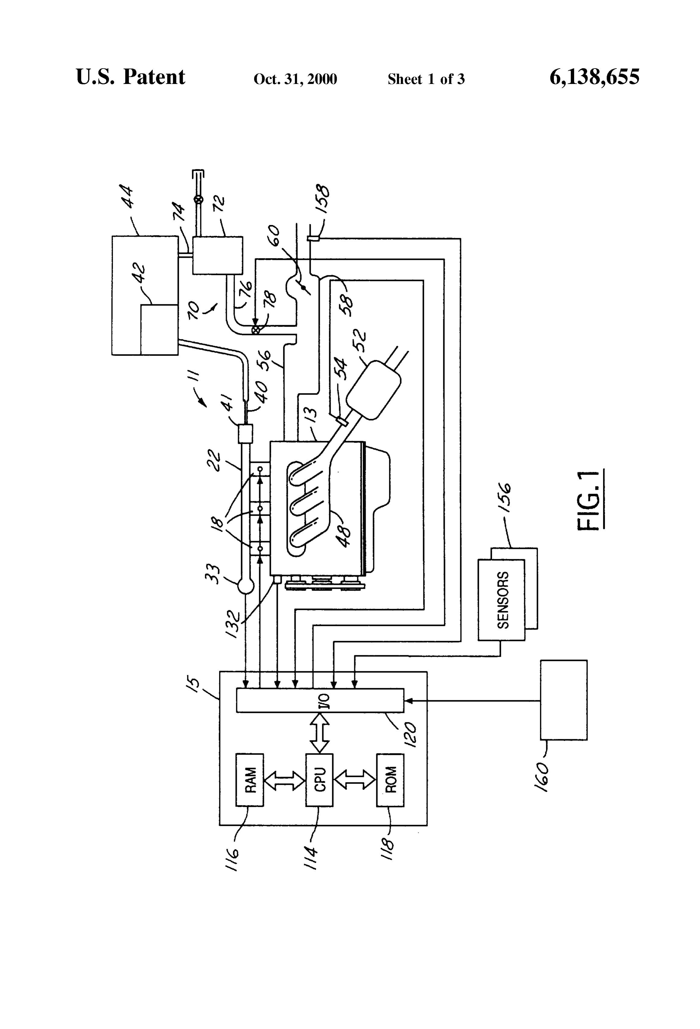
Referring now to FIG. 2, according to the present 65 invention, a flowchart of a routine performed by controller
The invention will now be described, by way of example, 15 to fuel pulse width signal (FPW) is now described. Fuel with reference to the accompanying drawings, in which: pulse width signal (FPW) is the signal sent by controller 15
Page 6
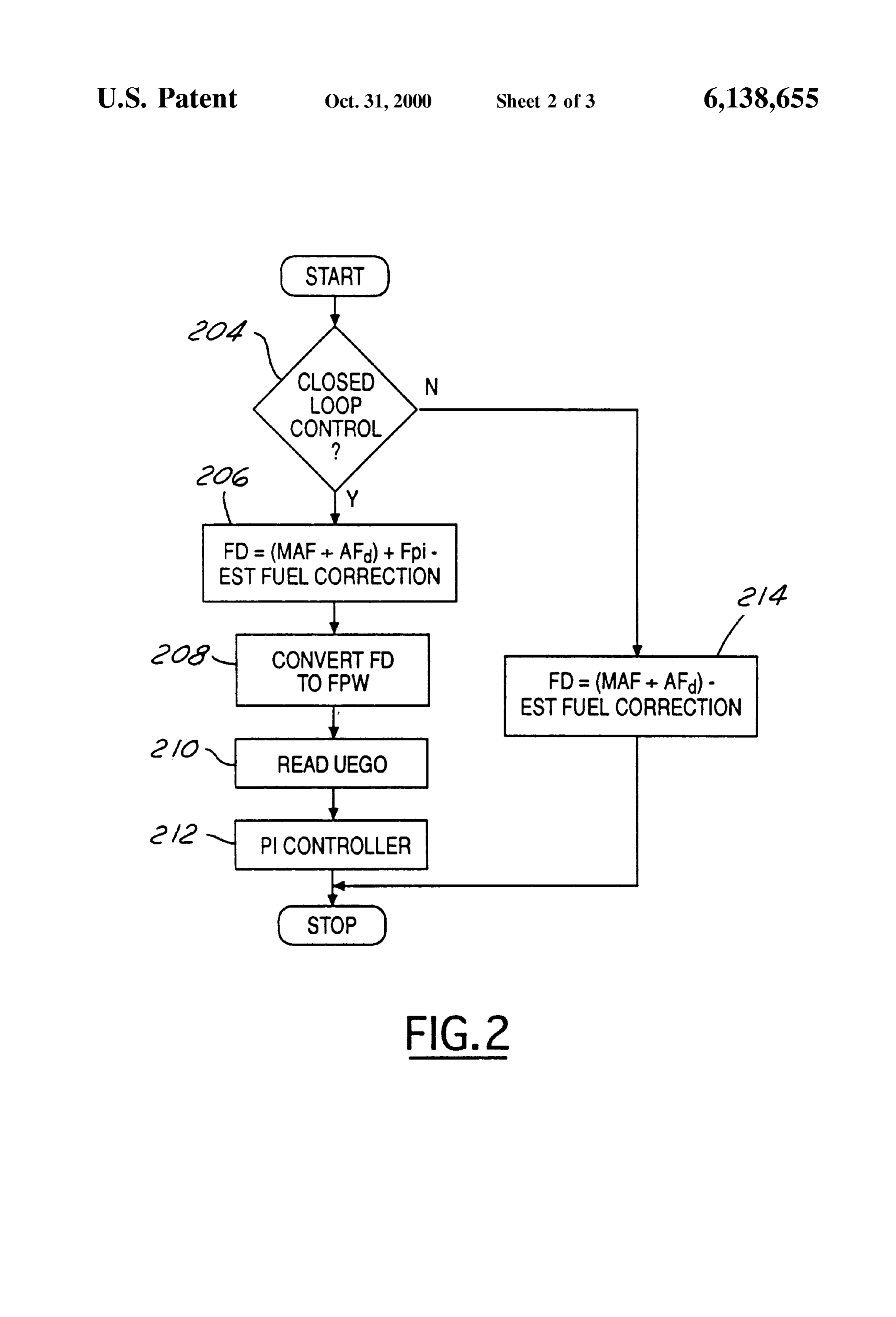
to fuel injectors 18 to deliver the desired quantity of fuel to Error minus the EstFuelerror minus the EstPurge Vol. This engine 13. A determination is first made whether closed-loop error will be used as described later herein with particular air/fuel control is to be commenced (step 204) by monitoring reference to step 318 to update the fuel error model and the engine operation conditions Such as temperature. When purge model Simultaneously.
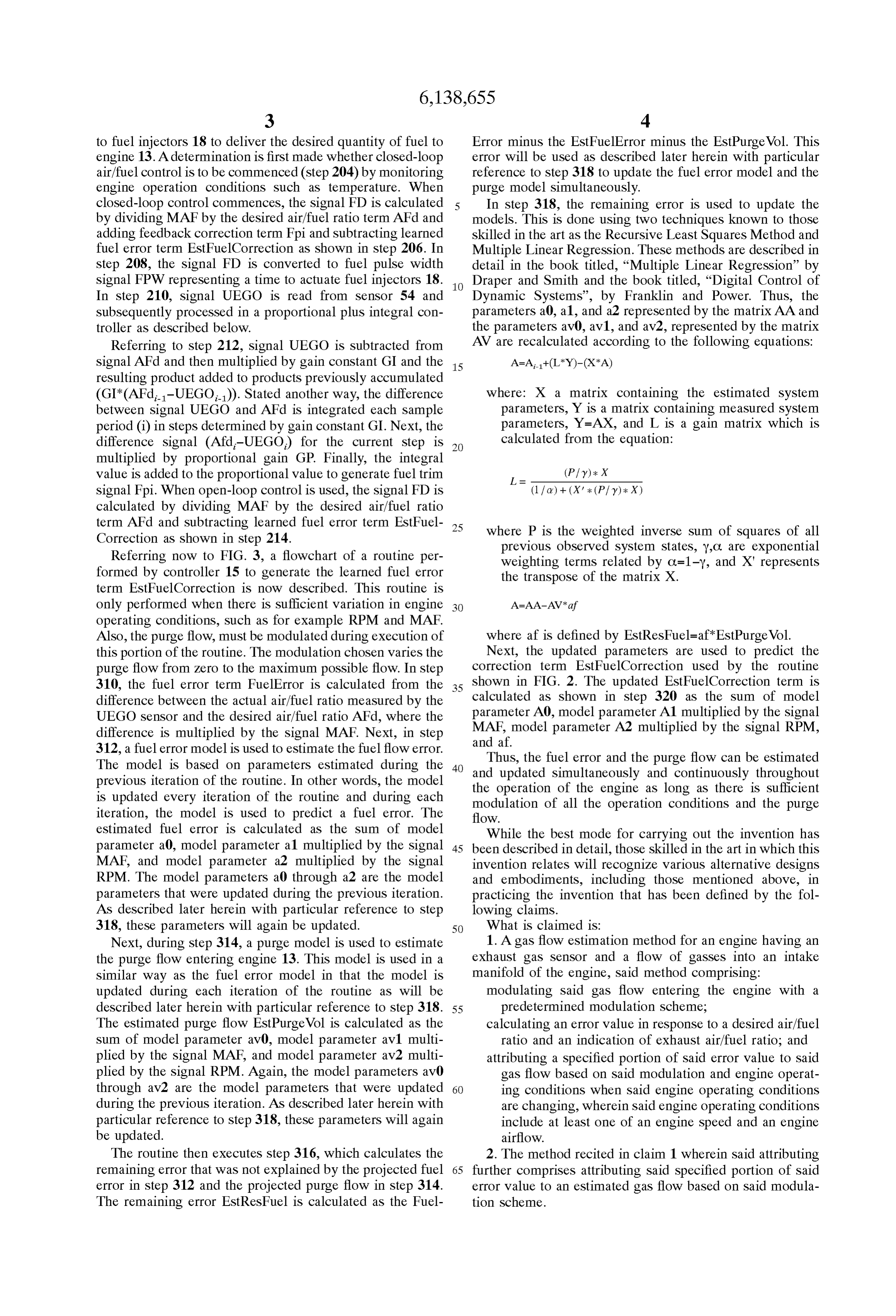
closed-loop control commences, the Signal FD is calculated In Step 318, the remaining error is used to update the by dividing MAF by the desired air/fuel ratio term AFd and models. This is done using two techniques known to those adding feedback correction term Fpi and Subtracting learned skilled in the art as the Recursive Least Squares Method and fuel error term EstFuelCorrection as shown in step 206. In Multiple Linear Regression. These methods are described in step 208, the signal FD is converted to fuel pulse width detail in the book titled, “Multiple Linear Regression” by signal FPW representing a time to actuate fuel injectors 18. Draper and Smith and the book titled, “Digital Control of In step 210, signal UEGO is read from sensor 54 and Dynamic Systems”, by Franklin and Power. Thus, the Subsequently processed in a proportional plus integral con parameters a0, a1, and a2 represented by the matrix AA and troller as described below. the parameters av0, av1, and av2, represented by the matrix Referring to step 212, signal UEGO is subtracted from AV are recalculated according to the following equations: Signal AFd and then multiplied by gain constant GI and the 15 resulting product added to products previously accumulated
(GI*(AFd-UEGO)). Stated another way, the difference where: X a matrix containing the estimated System between Signal UEGO and AFd is integrated each Sample parameters, Y is a matrix containing measured System period (i) in steps determined by gain constant GI. Next, the parameters, Y=AX, and L is a gain matrix which is difference signal (Afd-UEGO) for the current step is calculated from the equation: multiplied by proportional gain GP. Finally, the integral value is added to the proportional value to generate fuel trim (Pfy) : X
Signal Fpi. When open-loop control is used, the Signal FD is (1 fa) + (X : (Pfy): X) calculated by dividing MAF by the desired air/fuel ratio term AFd and subtracting learned fuel error term EstFuel 25 where P is the weighted inverse sum of squares of all Correction as shown in step 214. previous observed System States, Y.C. are exponential Referring now to FIG. 3, a flowchart of a routine per weighting terms related by C=1-y, and X" represents formed by controller 15 to generate the learned fuel error the transpose of the matrix X. term EstFuelCorrection is now described. This routine is only performed when there is Sufficient variation in engine operating conditions, such as for example RPM and MAF.
Also, the purge flow, must be modulated during execution of where af is defined by EstResFuel=af EstPurge Vol. this portion of the routine. The modulation chosen varies the Next, the updated parameters are used to predict the purge flow from Zero to the maximum possible flow. In Step correction term EstFuelCorrection used by the routine 310, the fuel error term FuelBrror is calculated from the 35 shown in FIG. 2. The updated EstFuelCorrection term is difference between the actual air/fuel ratio measured by the calculated as shown in step 320 as the sum of model parameter A0, model parameter A1 multiplied by the Signal
UEGO sensor and the desired air/fuel ratio AFd, where the difference is multiplied by the signal MAF. Next, in step MAF, and af.
model parameter A2 multiplied by the signal RPM, 312, a fuel error model is used to estimate the fuel flow error.
The model is based on parameters estimated during the 40 andThus, the fuel error and the purge flow can be estimated previous iteration of the routine. In other words, the model the operation Simultaneously updated and continuously throughout is updated every iteration of the routine and during each modulation of all the operation long of the engine as as there is Sufficient conditions and the purge iteration, the model is used to predict a fuel error. The flow.
estimated fuel error is calculated as the Sum of model While the best mode for carrying out the invention has parameter a0, model parameter a1 multiplied by the Signal 45 been described in detail, those skilled in the art in which this MAF, and model parameter a2 multiplied by the Signal invention relates will recognize various alternative designs RPM. The model parameters a0 through a2 are the model and embodiments, including those mentioned above, in parameters that were updated during the previous iteration. practicing the invention that has been defined by the fol AS described later herein with particular reference to Step lowing claims.
318, these parameters will again be updated. 50 What is claimed is:
Next, during Step 314, a purge model is used to estimate 1. A gas flow estimation method for an engine having an the purge flow entering engine 13. This model is used in a exhaust gas Sensor and a flow of gasses into an intake similar way as the fuel error model in that the model is manifold of the engine, Said method comprising: updated during each iteration of the routine as will be modulating Said gas flow entering the engine with a described later herein with particular reference to step 318. 55 predetermined modulation Scheme, The estimated purge flow EstPurge Vol is calculated as the calculating an error value in response to a desired air/fuel Sum of model parameter av0, model parameter av1 multi ratio and an indication of exhaust air/fuel ratio; and plied by the signal MAF, and model parameter av2 multi attributing a Specified portion of Said error value to Said plied by the signal RPM. Again, the model parameters av0 gas flow based on Said modulation and engine operat through av2 are the model parameters that were updated 60 ing conditions when said engine operating conditions during the previous iteration. AS described later herein with are changing, wherein Said engine operating conditions particular reference to Step 318, these parameters will again include at least one of an engine Speed and an engine be updated. airflow.
The routine then executes step 316, which calculates the 2. The method recited in claim 1 wherein said attributing remaining error that was not explained by the projected fuel 65 further comprises attributing Said Specified portion of Said error in step 312 and the projected purge flow in step 314. error value to an estimated gas flow based on Said modula The remaining error EstResFuel is calculated as the Fuel tion Scheme.
Page 7
S 6 3. The method recited in claim 1 wherein said gas flow 8. The method recited in claim 7 further comprising comprises a flow of purged fuel vapors. Suspending Said mapping Step in response to a lack of Said 4. The method recited in claim 1 further comprising change in Said engine operating conditions. attributing a difference between Said error value and Said 9. The method recited in claim 7 wherein said predeter Specified portion to a fueling error. mined modulation Scheme comprises modulating Said purge 5. The method recited in claim 1 further comprising
Suspending Said attributing in response to a lack of Said flow between a predetermined minimum value and a pre chance in Said conditions. determined maximum value.
6. The method recited in claim 1 further comprising 10. The method recited in claim 7 wherein said fueling adjusting a fuel injection amount based on Said estimated error is a first function of a first Set of engine operating gas flow. conditions and Said flow is a Second function of a Second Set 7. A flow estimation method for an engine having an of engine operating conditions. exhaust gas Sensor, Said method comprising: 11. The method recited in claim 10 wherein said first set modulating a flow entering the engine with a predeter of engine operating conditions includes engine airflow, mined modulation Scheme; 15 engine Speed, and purge vapor flow.
calculating a fueling difference in response to a difference 12. The method recited in claim 10 wherein said second between a desired air/fuel ratio and a measured exhaust air/fuel ratio; and Set of engine operating conditions includes engine airflow Simultaneously mapping Said fueling difference to a fuel and engine Speed.
ing error and to an estimated flow based on Said 13. The method recited in claim 7 wherein said flow is a modulation Scheme and a change in engine operating fuel vapor Surge flow.
conditions to appropriately assign said fueling differ ence to Said fueling error and Said estimated flow.
Provenance
- Collection
- Cited prior art
- Original PDF
- patentimages.storage.googleapis.com →
- Filed
- 1999-11-10
- Pages
- 7
- Method
- pdftotext (the PDF's own text layer) + pdftoppm 300dpi page scans
- Source
- Google Patents bibliographic record
- Granted
- 2000-10-31
- Inventors
- James Michael Kerns; William Edward Ortell; Xiao Wu; Ford Global Technologies LLC
- Transcribed from
- patentimages.storage.googleapis.com →