patent · US5816223
Evaporative emission control system for providing fuel to vapor to automotive engine
6 October 1998
Page 1 — bibliographic record
United States Patent (19) 11 Patent Number: 5,816,223 Jamrog et al. (45) Date of Patent: Oct. 6, 1998 54 EVAPORATIVE EMISSION CONTROL 5,230,319 7/1993 Otsuka .................................... 123/520 SYSTEM FOR PROVIDING FUEL TO WAPOR 5,347,971 9/1994 Kobayashi ... 123/520 TO AUTOMOTIVE ENGINE 5,400,759 3/1995 Ishida ...... ... 123/520 5,411,007 5/1995 Narita. ... 123/520 75 Inventors: James Richard Jamrog, Novi, David 5,460,143 10/1995 Narita.
Chester Waskiewicz, Livonia: 5,477,837 12/1995 Ikebuchi .................................. 123/520 s s 5,592,923 1/1997 Machida .................................. 123/520
Marianne L. Vykydal, Onsted, all of 5,596.972 1/1997 Sultan et al..
5,606,955 3/1997 Yuda ....................................... 123/520
73 Assignee: Ford Global Technologies, Inc., 5,669,360 9/1997 Hyodo et al.. Dearborn, Mich. 5,669,362 9/1997 Shinohara et al..
Primary Examiner-Carl S. Miller 22 Filed: Dec. 29, 1997 Attorney, Agent, or Firm Jerome R. Drouillard 51 Int. Cl. ............................ F02M 33/00; F02D 31/00 57 ABSTRACT 52 U.S. Cl. ............................................. 123/520; 123/357 58 Field of Search ..................................... 123/357,520, An engine controller tracks purge System pressure within a 123/519, 518, 516, 521 Vapor line extending from a fuel tank to a carbon canister and, in the event that pressure changes at an unduly high 56) References Cited rate, operates to restrict the purging of vapor from a carbon canister.
5,111,796 5/1992 Ogita. 14 Claims, 2 Drawing Sheets
34 'as
36 2 LTRANSDUCER
E 20 /?
22 (X)7/6
ECM 7s CARBON 24 12 CANISTER 40 /4
ENGINE
Page 2
Drawing sheet — no readable text.
Page 3
Drawing sheet — no readable text.
Page 4
EVAPORATIVE EMISSION CONTROL through the engine, the greater the ability of the engine to SYSTEM FOR PROVIDING FUEL TO WAPOR tolerate changes in the fuel content of the purge flow TO AUTOMOTIVE ENGINE entering the engine from the carbon canister and fuel tank. The threshold value for the time rate of change of fuel vapor
FIELD OF THE INVENTION preSSure is determined by the controller from a lookup table The invention relates to a System for allowing fuel vapor using a measured value for the total mass of air flowing through the engine as an independent variable.
arising within an automotive vehicle's liquid fuel System to According to another aspect of the present invention, a be consumed by an engine without adversely affecting method for controlling the flow of evaporative fuel vapor to engine operation.
an automotive engine having a liquid fuel Storage tank, in a
BACKGROUND OF THE INVENTION System for conveying fuel vapor to the engine, includes the Steps of establishing a vapor flow from at least one Source of
Government regulations concerning the release into the fuel vapor to the engine; periodically measuring a purge atmosphere of various exhaust emission constituents from System operating pressure within the vapor conveying Sys automotive vehicles are becoming increasing more Strin 15 tem; calculating the time rate of change of the measured gent. AS the Stringency related to emissions of oxide of purge System preSSure, and adjusting the flow of vapor to the nitrogen, carbon monoxide, and unburned hydrocarbons, engine in the event that the calculated time rate of change of inter alia, becomes greater, it is becoming increasingly the purge System pressure exceeds a predetermined thresh necessary to control the engine combustion process So as to old. According to another aspect of the present method, the avoid unnecessary instabilities. Of course, those skilled in flow of vapor to the engine is terminated in the event a time the art know that not only engine tailpipe emissions are rate of change of fuel vapor pressure exceeds a predeter regulated, but also evaporative emissions. In point of fact, mined threshold. This threshold is based upon a measured evaporative emission control is a very important consider flow of fuel through the engine or may be based upon a ation in automotive design and necessitates that fuel Vapor measured flow of air through the engine, or upon the arising from the engine fuel System be drawn into the engine 25 percentage of fuel flowing through the engine which is and burned. Because the fuel vapor can be combusted by the furnished by the evaporative emission control system. The engine, a discontinuous flow of vapor may cause combus flow of vapor to the engine may be terminated for a variable tion instability, or perhaps even engine roughness or Stalling. period of time in the event that the rate of change of fuel The present System is intended to allow vapor to be pro Vapor pressure exceeds a predetermined threshold, with the cessed and burned by an automotive engine without causing flow of vapor being reestablished after a variable period of attendant instability problems. time has run.
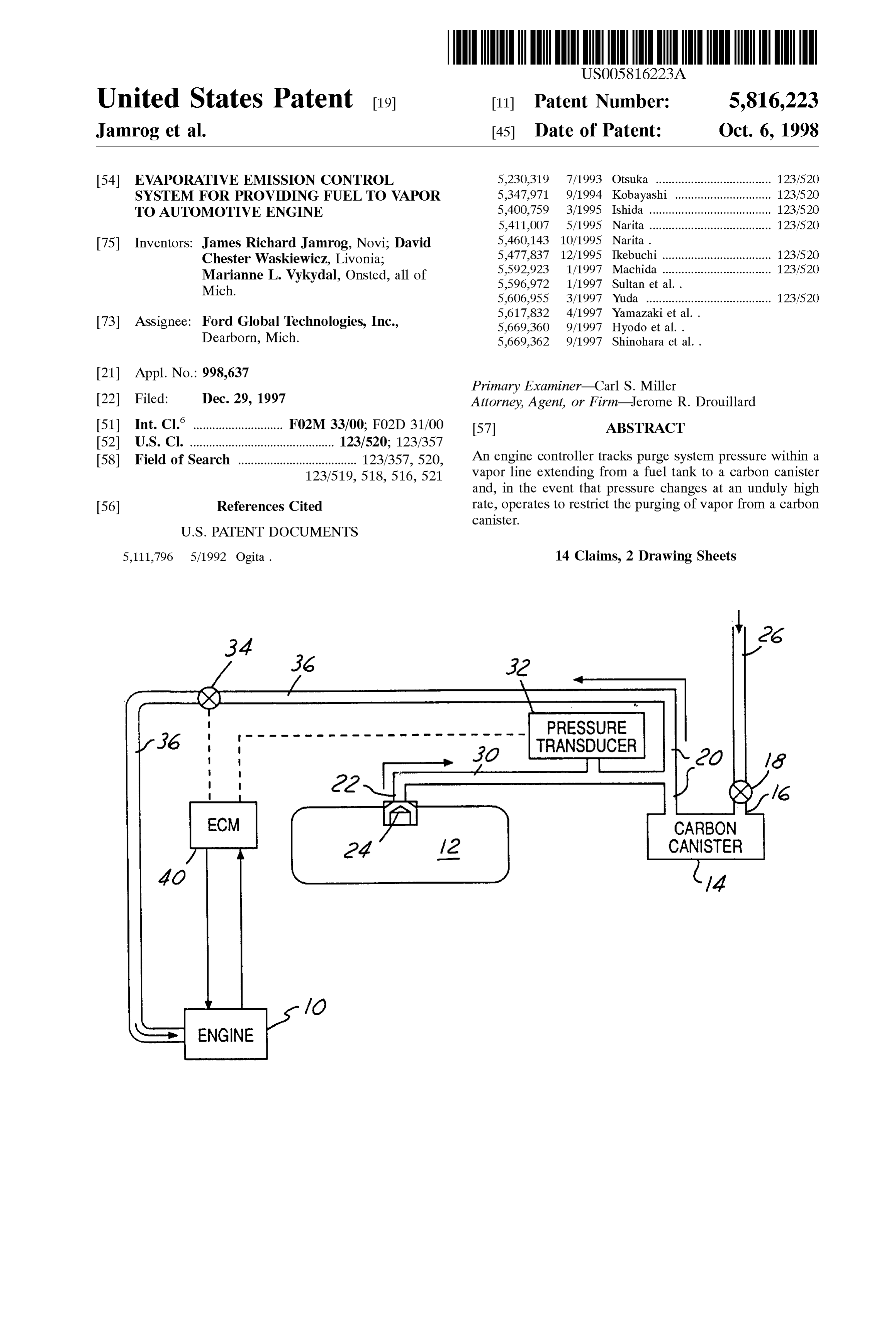
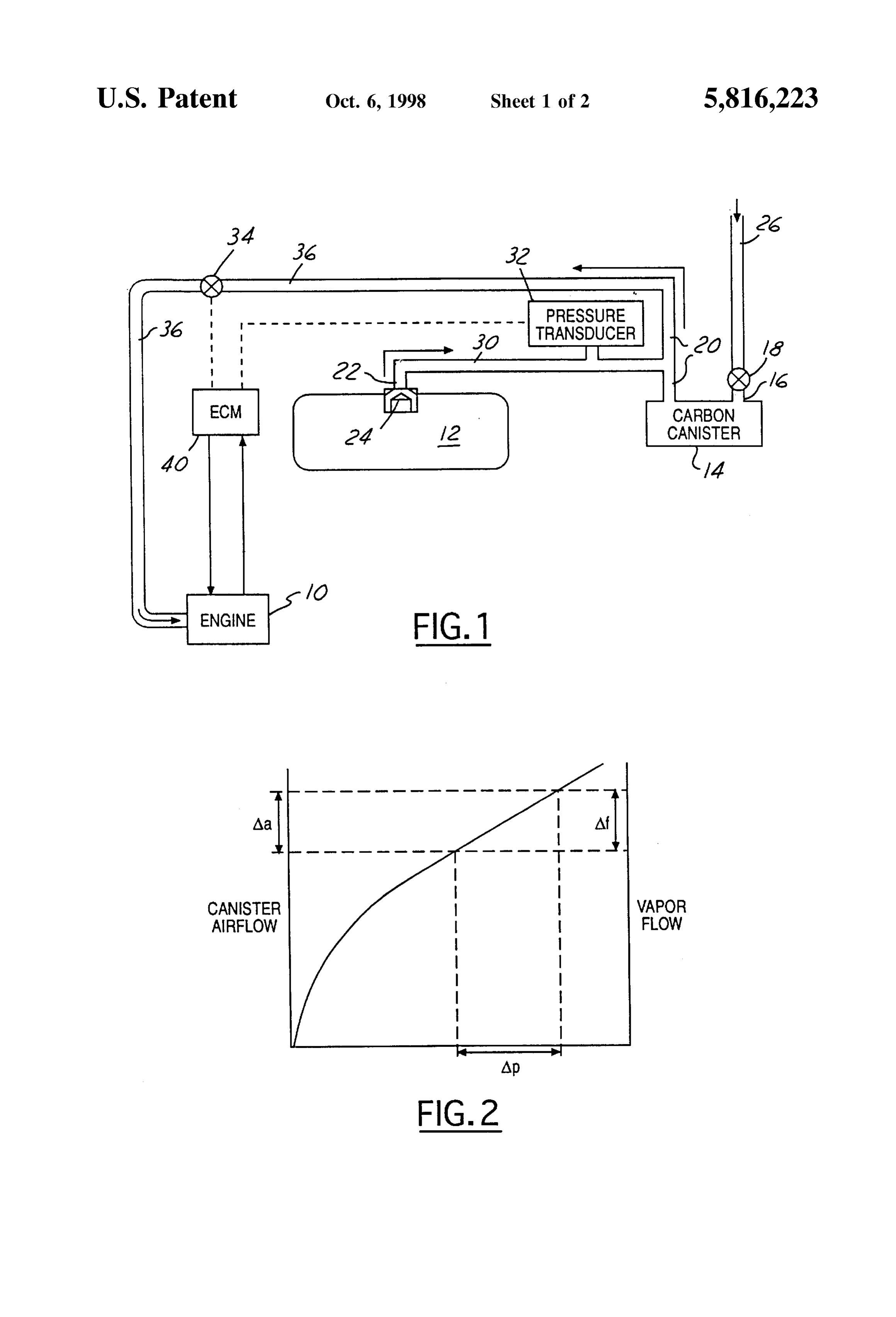
U.S. Pat. No. 5,460,143 discloses an evaporative emis BRIEF DESCRIPTION OF THE DRAWINGS sions control system in which a pressure transducer stops purging of a carbon canister in the event that fuel tank 35 FIG. 1 is a Schematic representation of an automotive preSSure falls to a negative value. The present System is engine having a fuel vapor venting and carbon canister intending to control purging not only when tank preSSure purging System according to the present invention. goes to a negative value, but in response to rapid fluctuations FIG. 2 is a plot of carbon canister air flow, equivalent in the tank preSSure at a positive preSSure or negative Vapor flow, and pressure drop of a System according to the preSSure, which may cause the air and fuel vapor entering 40 present invention.
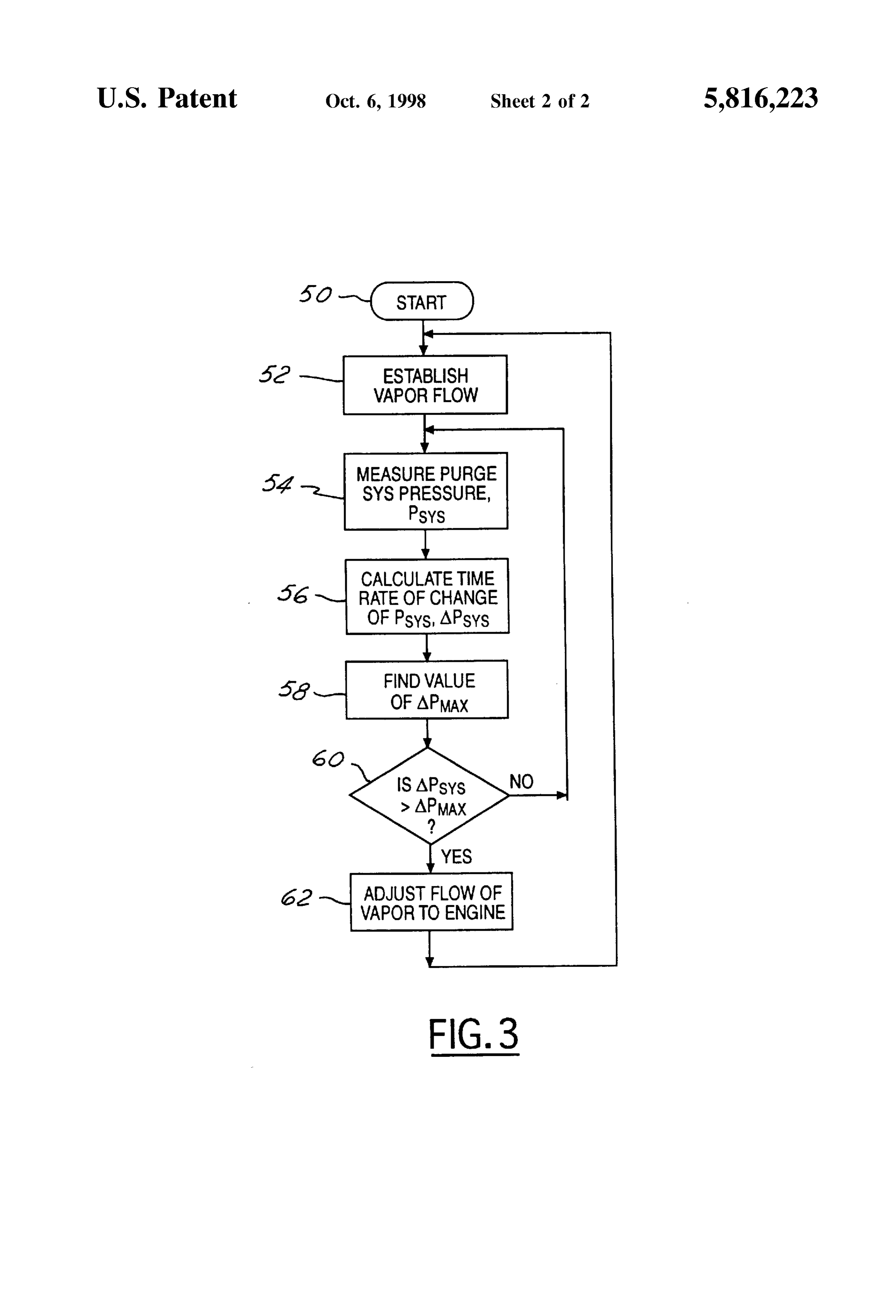
the engine from the purge line of a carbon evaporative FIG. 3 is a flow diagram illustrating operation of a System emissions control canister to upset the combustion process. according to the present invention. SUMMARY OF THE INVENTION DETAILED DESCRIPTION OF PREFERRED
EMBODIMENTS
A System for providing evaporative fuel vapor to an 45 automotive engine includes a liquid fuel Storage tank having As shown in FIG. 1, automotive engine 10 receives fuel an outlet port for allowing fuel vapor to exit the tank, and a from liquid fuel tank 12. Vapor generated by fuel contained carbon canister for Storing fuel Vapor generated within the within fuel tank 12 and furnished to engine 10 is controlled fuel tank. The carbon canister has an inlet port for receiving by a System according to the present invention. Vapor air and an outlet port. The outlet port is adapted for both 50 leaving tank 12 past vapor vent valve 24 and outlet port 22 receiving fuel vapor from the tank and acting as an outlet for enters vapor line 30 before passing to outlet port 20 of a flow of Stored fuel vapor and air when the canister is carbon canister 14. During periods in which the vehicle is purged. A vapor line connects the tank outlet port and the not being operated, fuel vapor is Stored within carbon outlet port of the carbon canister. A purge valve allows vapor canister 14. When engine 10 is being operated, canister vent to flow from the fuel tank and the outlet port of the carbon 55 Valve 18 is open and ambient air is drawn through purge air canister through the purge line and into the engine. A inlet 26, then through carbon canister 14 and through outlet preSSure transducer Senses purge System pressure within the port 20, and then through purge line 36 past purge valve 34 Vapor line. Finally, a controller connected with the purge and into engine 10. Electronic control module (ECM) 40 Valve and the purge System pressure transducer tracks fuel which controls the rate of purging by operating purge valve Vapor pressure within the vapor line within Successive 60 34, receives evaporative emission control (purge) system Sample periods and operates the purge valve to restrict preSSure information from preSSure transducer 32. purging in the event that the time rate of change and the fuel Air drawn through carbon canister 14 causes desorption Vapor pressure exceeds a threshold value. of fuel vapor Stored in the canister; the fuel Vapor and air The controller determines the threshold value for the flowing from canister 14 are combined with vapor from fuel maximum allowable time rate of change of fuel vapor 65 tank 12.
preSSure as a function of the total mass of air flowing During the vapor purging process, pressure transducer 32 through the engine. In general, the greater the mass flow is used to track the purge System pressure within vapor line
Page 5
30. The purge System pressure may change for a variety of caused by rapid excursions in the fuel content of the purge reasons. For example, the composition of the fuel and its flow will be more easily tolerated. Other engine operating temperature will affect pressure within vapor line 30. Slow parameters or combinations of parameters known to those changes in pressure are easily handled by conventional skilled in the art and Suggested by this disclosure may be means which compensate for changes in air fuel ratio by employed for the purpose of determining APA. detecting Such changes by means of an exhaust gas oxygen Having determined AP at block 58, controller 40 Sensor (not shown). The problem with relying Solely upon an moves to block 60 where APA is compared with APss. In exhaust gas oxygen Sensor to detect changes in the fuel the event the AP'ss is greater than APA, controller 40 content of the air and vapor entering the engine through moves to block 62, wherein the flow of vapor to the engine purge line 36 is that the effect of the vapor entering into the is adjusted. It has been determined that it is frequently combustion process cannot be known by the ECM 40 until advisable in the event that engine 10 is operating at idle to the air fuel ratio Sensor, which is downstream of the engine, either shut off or greatly reduce the flow of vapor to engine shows a reaction. This may cause problems because the 10 for a period of time. The quantity of time for either engine Stability is already impaired by the time a change in Shutting off or greatly reducing the purge flow may be based the exhaust gas composition is noted or determined by an 15 upon Such parameters as the duration of time for which the exhaust gas Oxygen Sensor. engine has been operating Since a cold Startup, exhaust The present System relies on the phenomenon shown in aftertreatment catalyst temperature, coolant temperature, or FIG. 2 to prevent combustion instability by allowing imme other engine operating parameters known into those skilled diate reaction to a change in the amount of vapor injected in the art and Suggested by this disclosure. into the purge flow by fuel tank 12. If at block 60 the answer is no, processor 40 will return FIG. 2 illustrates carbon purge system air flow and fuel to block 54 and remeasure purge System fuel vapor pressure, Vapor flow as a function of pressure drop, as measured by calculate a new Value for APss, find a new Value of APA, preSSure transducer 32. Note that for a given change in purge compare APA, and AP'ss, and So forth, to assure that System pressure, Ap (on the abscissa), which indicates a 25 engine 10 is not confronted with a situation where stable change in the pressure measured by pressure transducer 32, operation is impaired by a rapid change in air fuel ratio due corresponding changes Aa for purge air flow through carbon to fuel vapor arising from either fuel tank 12 or carbon canister 14 and Af, for inferred fuel vapor flow are shown. canister 14. This type of Situation may occur when, for In other words, a change in purge System pressure measured example, the fuel is warmed and the fuel tank is partially by pressure transducer 32 corresponds to a change in Vapor empty, which in turn may cause fuel to Slosh on the wall of flow during the purging process. It is rapid changes in the the tank and to flash into vapor, producing a considerable measured pressure and hence in the mass flow of fuel vapor increase in the pressure in tank 12 and a corresponding to engine 10 which the present System is intended to detect increase in the flow of vapor into engine 10 past purge valve and compensate for. 34.
ECM 40 is an engine controller of conventional type 35 In another aspect of the present invention, in the event that known to those skilled in the art and selected in view of this the pressure trend detected by pressure transducer 32 disclosure. AS described above, controller 40 operates purge changes in Sign-in other words, changes from a positive Valve 34 and receives Signals from pressure transducer 32. Slope indicating an increasing trend, to a negative slope, It has been determined that the ability of one engine to indicating a decreasing trend, processor 40 will immediately tolerate changes in the amount of fuel Vapor flowing into the 40 begin a new Sample period. The same is true when the purge engine from the purge System is Such that in the event that System preSSure trend Switches from a negative slope to a 15% or more of the fuel originates from the purge System, positive slope. In this manner, changes in vapor flow may be as opposed to the fuel injection System, a change of as little detected with less of a time lag, So as to allow more time to as 0.16", H2O in the purge System pressure should be reduce purge flow without upsetting engine operation. handled by temporarily halting the purging process. 45
While the invention has been shown and described in its
FIG. 3 illustrates the function of a system according to preferred embodiments, it will be clear to those skilled in the present invention. Starting at block 50, controller 40 estab arts to which it pertains that many changes and modifica lishes vapor flow by opening purge Valve 34, provided tions may be made thereto without departing from the Scope necessary threshold conditions have been met. For example, of the invention.
Vapor flow is usually not initiated when the engine is under 50 We claim:
cold operation as when it is being warmed up at a lower 1. An evaporative emission control System for providing ambient temperature. Alternatively, purging may begin as fuel vapor to an automotive engine, comprising: Soon as the engine is started. a liquid fuel Storage tank having an outlet port for Once the initial conditions are met and vapor flow has allowing fuel vapor to exit the tank, been established at an appropriate level at block 52, con 55 a carbon canister for Storing fuel vapor generated within troller 40 moves to block 54, wherein purge system pressure the fuel tank, with the carbon canister having an inlet Pss is determined. The purge System preSSure is periodi port for receiving air and an outlet port, with the outlet cally remeasured, and at block 56, the Successively mea port being adapted for both receiving fuel vapor from Sured values of Pss are used to calculate the time rate of the fuel tank and acting an outlet for Stored fuel vapor change of Pss, which is identified as APss. 60 and air when the canister is purged; At block 58, controller 40 finds the value AP, which is a vapor line connecting the tank outlet port and the outlet representative of the maximum value of APs which engine port of the carbon canister; 10 is capable of handling at a particular operating condition. a purge valve for allowing vapor to flow from the fuel tank APA may be based upon air flow through the engine. and the outlet port of the carbon canister through a Alternatively, fuel flow may be employed for calculating 65 purge line and into the engine; APA by considering that when the engine is being oper a pressure transducer for Sensing a purge System pressure ated at a high rate of fuel consumption, the perturbation within the vapor line; and
Page 6
S 6 a controller connected with the purge valve and the purge periodically measuring a purge System preSSure within the System pressure transducer, with Said controller track purge System, ing the purge System pressure within the vapor line calculating the time rate of change of the measured purge within Successive Sample periods and operating the System pressure; and purge valve to restrict purging in the event that the time 5 adjusting the flow of purged vapor to the engine in the rate of change of the purge System pressure exceeds a event that the calculated time rate of change of the threshold value. purge System pressure exceeds a predetermined thresh 2. A System according to claim 1, wherein Said controller old.
immediately begins tracking the purge System pressure 8. A method according to claim 7, wherein the flow of during a new Sample period in the event that the purge Vapor to the engine is terminated in the event that the time System preSSure Switches from a declining trend to an termined rate of change of purge System preSSure exceeds a prede increasing trend. threshold.
3. A System according to claim 1, wherein Said controller mined thresholdaccording 9. A method is based to claim 7, wherein said predeter upon a measured flow of fuel immediately begins tracking the purge System pressure through the engine.
during a new Sample period in the event that the purge 15 10. A method according to claim 7, wherein said prede System pressure Switches from an inclining trend to a termined threshold is based upon a measured flow of air decreasing trend. through the engine.
4. A System according to claim 1, wherein the controller 11. A method according to claim 7, wherein the purge flow determines Said threshold value for the time rate of change to the engine is terminated for a variable period of time in of purge System pressure as a function of the total mass of the event that the rate of change of purge System preSSure air flowing through the engine. exceeds a predetermined threshold, with the purge flow 5. A System according to claim 1, wherein the controller being reestablished after the variable period of time has run. determines Said threshold value for the time rate of change 12. A method according to claim 7, wherein Said control of purge System pressure from a lookup table, using a ler immediately begins measuring the purge System preSSure measured value for the total mass of air flowing through the 25 during a new Sample period in the event that the purge engine as an independent variable. System pressure Switches from a declining trend to an 6. A System according to claim 1, wherein the controller increasing trend.
determines Said threshold value for the time rate of change 13. A System according to claim 7, wherein Said controller of purge System pressure as a function of the fraction of fuel immediately begins measuring the purge System preSSure flowing through the engine which is furnished by Said during a new Sample period in the event that the purge evaporative emission control System. System pressure Switches from an inclining trend to a 7. A method for controlling a flow of evaporative fuel decreasing trend.
Vapor to an automotive engine having a liquid fuel Storage 14. A system according to claim 7, wherein said controller tank, a carbon vapor Storage canister, and a purge System for immediately begins measuring the purge System preSSure conveying fuel vapor to the engine from the fuel tank and the 35 during a new Sample period in the event that the trend of the carbon canister, with Said method comprising the Steps of: purge System pressure changes sign. establishing a vapor flow from the fuel tank and carbon canister through the purge System and into the engine; k k k k k
Provenance
- Collection
- Cited prior art
- Original PDF
- patentimages.storage.googleapis.com →
- Filed
- 1997-12-29
- Pages
- 6
- Method
- pdftotext (the PDF's own text layer) + pdftoppm 300dpi page scans
- Source
- Google Patents bibliographic record
- Granted
- 1998-10-06
- Inventors
- James Richard Jamrog; David Chester Waskiewicz; Marianne L. Vykydal; Ford Global Technologies LLC
- Transcribed from
- patentimages.storage.googleapis.com →