patent · US6155239
Fuel vapor system
5 December 2000
Page 1 — bibliographic record
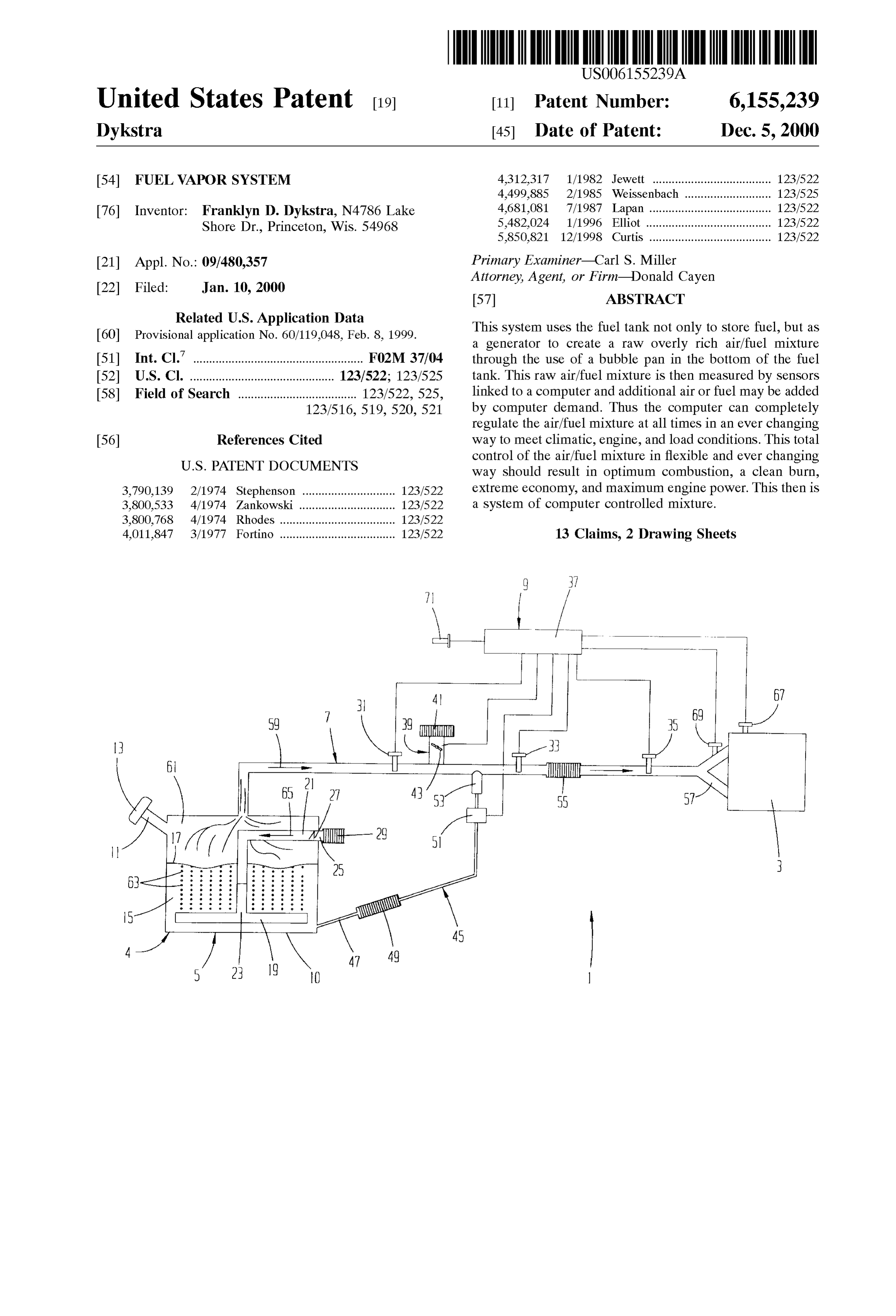
United States Patent (19) 11 Patent Number: 6,155,239 Dykstra (45) Date of Patent: Dec. 5, 2000 54 FUEL VAPOR SYSTEM 4.312,317 1/1982 Jewett ..................................... 123/522 4,499,885 2/1985 Weissenbach ... 123/525 76 Inventor: Franklyn D. Dykstra, N4786 Lake 4,681,081 7/1987 Lapan. . . 123/522 Shore Dr., Princeton, Wis. 54968 5,482,024 1/1996 Elliot ... ... 123/522 5,850,821 12/1998 Curtis ...................................... 123/522 21 Appl. No.: 09/480,357 Primary Examiner-Carl S. Miller Attorney, Agent, or Firm Donald Cayen 22 Filed: Jan. 10, 2000 57 ABSTRACT 60 poss R. Application pit, 8, 1999. This system uses the fuel tank not only to store fuel, but S a generator to create a raw overly rich air/fuel mixture (51) Int. Cl. ............................................... F02M 37/04 through the use of a bubble pan in the bottom of the fuel 52 U.S. Cl. ............................................. 123/522; 123/525 tank. This raw air/fuel mixture is then measured by Sensors 58 Field of Search ..................................... 123/522,525, linked to a computer and additional air or fuel may be added 123/516,519, 520, 521 by computer demand. Thus the computer can completely regulate the air/fuel mixture at all times in an ever changing 56) References Cited way to meet climatic, engine, and load conditions. This total control of the air/fuel mixture in flexible and ever changing
3,790,139 2/1974 Stephenson ............................. 123/522 extreme economy, and maximum engine power. This then is 3,800,533 4/1974 Zankowski ... . . 123/522 a System of computer controlled mixture. 3,800,768 4/1974 Rhodes ......... ... 123,522 4,011,847 3/1977 Fortino ..... . . 123/522 13 Claims, 2 Drawing Sheets
Page 2
Drawing sheet — no readable text.
Page 3
Drawing sheet — no readable text.
Page 4
FUEL WAPOR SYSTEM downstream of the auxiliary air inlet and the auxiliary fuel inlet. A third Sensor is located in the fuel vapor passage
This is a continuation-in-part of U.S. patent application upstream of the engine manifold. Additional Sensors may be Ser. No. 60/119,048 filed Feb. 8, 1999. used in the engine and engine manifold. Another Sensor monitors atmospheric conditions. All the Sensors are con
BACKGROUND OF THE INVENTION nected to a computer.
1. Field of the Invention When the engine is started, the engine produces a vacuum This invention pertains to fuel delivery Systems, and more in the fuel vapor passage and the reservoir. The air inlet to particularly to Systems for delivering gaseous fuel to internal the reservoir opens to allow atmospheric air to flow to the combustion engines. bubble pan. The atmospheric air is diffused into myriad 2. Description of the Prior Art bubbles that rise through the fuel in the reservoir. Some fuel Vaporizes in the air bubbles Such that a fuel vapor is created
Various types of fuel delivery systems have been devel in a space in the reservoir above the fuel. The fuel vapor is oped for internal combustion engines. For example, carbu drawn from the reservoir into the fuel Vapor passage and retors have been in use for many years and are now highly 15 toward the engine.
refined. Similarly, direct fuel injection Systems are well Each Sensor measures the air/fuel ratio of the fuel vapor. known and in widespread use. The measured air/fuel ratio is compared in the computer to A common characteristic of prior fuel delivery Systems is a desired ratio. If the air/fuel ratio is too rich at the first that the fuel is vaporized at locations either within or very Sensor, the computer controls an auxiliary air inlet valve to close to the combustion cylinders. In carburetor Systems, the admit air into the fuel vapor passage. The computer controls carburetor is invariably located adjacent the engine intake the auxiliary air inlet valve to open the amount that produces manifold. In direct injection Systems, the fuel is not vapor the desired ratio as measured by the Second Sensor. ized until it is actually inside the combustion cylinder. In If the air/fuel ratio is too lean at the first sensor, the both types of Systems, therefore, a pump is required to auxiliary air inlet valve remains closed. Instead, the com deliver liquid fuel from a Storage tank to the engine. 25 puter controls the fuel pump to inject fuel from the reservoir
Despite their general Suitability for automotive into the fuel vapor passage at the auxiliary fuel inlet and thus applications, both carburetor and direct injection Systems increase the ratio to the desired amount as measured by the have certain disadvantages. Both types of Systems require Second Sensor. After the fuel vapor is thoroughly mixed, its high accuracy, and therefore expensive, components for ratio is measured a final time before it enters the engine proper operation. Especially with direct injection Systems, manifold.
those components include costly high pressure injector The computer determines the desired air/fuel ratio, which pumps. Both carburetor and direct injection Systems are changes highly susceptible to failure from dirt, moisture, and other conditionsalmost continuously depending on atmospheric contaminants, and Servicing a failed System requires Skill 35 Vapor System delivers aSpeed, and engine load, or temperature. The fuel and unproductive down time. In addition, the prior Systems times is optimum for the particular to fuel Supply the engine that at all prevailing conditions.
are not able to readily change the air/fuel ratio of the
Vaporized fuel. If desired, a blower can be used to positively pump air Thus, notwithstanding past technological developments through the bubble pan and fuel vapor passage to the engine. Also, exhaust gasses in automotive fuel Systems, further refinements to fuel 40 the air entering the reservoir. from the engine can be used to pre-heat delivery is highly desirable.
The method and apparatus of the invention, using a
SUMMARY OF THE INVENTION bubble pan that diffuses atmospheric air into liquid fuel, thus In accordance with the present invention, a fuel vapor delivers an ideal air/fuel ratio to an internal combustion System is provided that more efficiently and economically 45 engine. The Sensors and computer assure that the ideal delivers fuel to internal combustion engines than prior constantly air/fuel ratio is delivered, even though the ideal ratio is Systems. This is accomplished by apparatus that includes a changing.
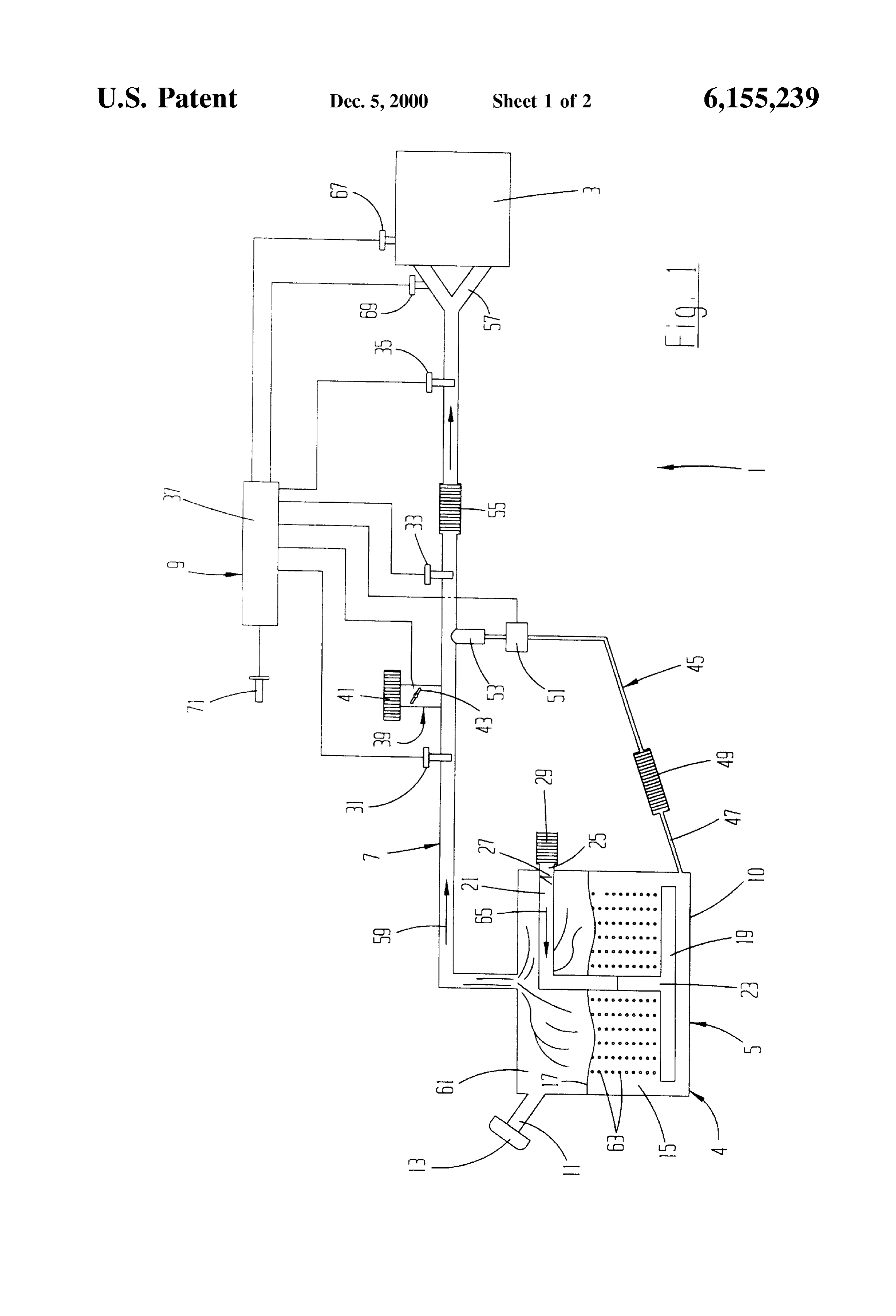
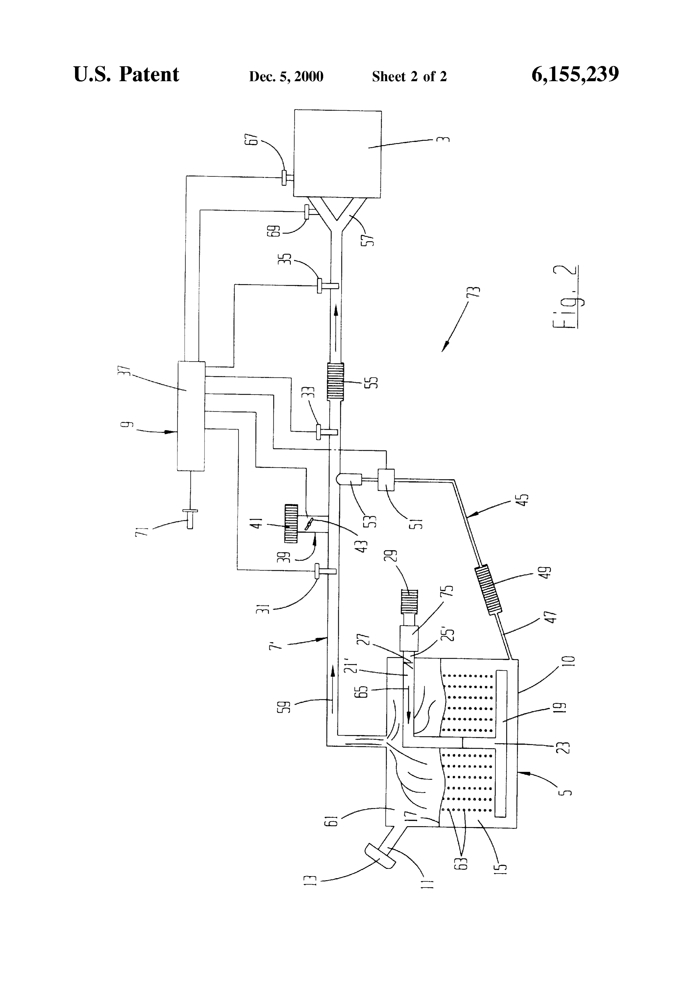
fuel vapor generator located remote from the engine. Other advantages, benefits, and features of the present According to one aspect of the invention, the fuel vapor invention will become apparent to those skilled in the art generator comprises a reservoir having an air inlet, a liquid 50 upon reading the detailed description of the invention. fuel inlet, and a fuel vapor outlet. The air inlet is open to the BRIEF DESCRIPTION OF THE DRAWINGS atmosphere when the engine is operating but is closed when the engine is not in operation. The fuel inlet is closed to the FIG. 1 is a Schematic diagram of the fuel vapor System of atmosphere when the engine is in operation. The fuel Vapor the invention.
outlet is connected by a Suitable fuel vapor passage to the 55 FIG. 2 is a schematic diagram of a modified embodiment intake manifold of the engine. Aliquid fuel line with a Small of the invention.
fuel pump leads from the reservoir to an auxiliary fuel inlet DETAILED DESCRIPTION OF THE in the fuel vapor passage. There is also an auxiliary air inlet INVENTION in the fuel vapor passage. Preferably, the auxiliary air inlet is upstream of the auxiliary fuel inlet. 60 Although the disclosure hereof is detailed and exact to Submerged in the fuel near the bottom of the reservoir is enable those skilled in the art to practice the invention, the a bubble pan. The bubble pan has a large number of very physical embodiments herein disclosed merely exemplify small holes in it. The bubble pan is connected to the air inlet the invention, which may be embodied in other specific by a tube. Structure. The Scope of the invention is defined in the claims A number of Sensors are present in the fuel vapor passage 65 appended hereto.
between the reservoir and the engine. A first Sensor is located Referring to FIG. 1, a fuel vapor system 1 is illustrated upstream of the auxiliary air inlet. A Second Sensor is located that includes the present invention. The fuel vapor System 1
Page 5
is particularly useful for delivering gaseous fuel to an atmospheric conditions Such as temperature, humidity, and internal combustion engine represented at reference numeral barometric pressure. Other Sensors, not shown, feed engine 3. The engine 3 may be any of a wide variety of engines as related data Such as Speed and gear ratio to the computer 37. are used in automotive, marine, and aeronautical applica Data from the sensors 67, 69, 71, and others is processed by tions. the computer to calculate the ideal air/fuel ratio for the The fuel vapor System 1 is comprised of a fuel vapor engine under the particular operating conditions at each moment.
generator 4, a fuel vapor passage 7, and a control 9 that assures that a proper air/fuel ratio is Supplied from the fuel The ideal air/fuel ratio as calculated by the computer 37 Vapor generator to the engine 3. Looking first at the fuel is compared with the actual ratio leaving the reservoir 5 as Vapor generator 4, it is comprised of a reservoir 5 having a measured by the sensor 31. If the actual air/fuel ratio as bottom wall 10, and a liquid fuel inlet 11. The fuel inlet 11 measured by the Sensor 31 is too rich, the computer Signals is tightly closed by a cap 13 when the engine is in operation. the auxiliary air inlet valve 43 to open. As a result, atmo Spheric air enters the fuel vapor passage 7 to dilute the fuel
As shown, the reservoir is filled with liquid fuel 15 to a level Vapor. The corrected ratio is measured again by the Sensor 33 17. for comparison with the ideal ratio from the computer. The
Submerged under the fuel 15 in the reservoir 5 is a bubble computer operates the auxiliary air inlet valve as much as pan 19. The bubble pan 19 preferably has a size and shape necessary until the air/fuel ratio sensed by the sensor 33 that closely approximates the size and shape of the reservoir matches the ideal ratio from the computer. bottom wall 10. The bubble pan is formed with a very large If the air/fuel ratio as measured by the sensor 31 is too number of Small holes, not shown. A tube 21 passes through lean compared with the ideal ratio set by the computer 37, the reservoir and connects at one end 23 to the bubble pan. the computer Signals the fuel injection pump 51 to operate A second end 25 of the tube 21 is open to the atmosphere. and inject liquid fuel into the fuel vapor passage 7. The rate There is a valve 27 and a filter 29 in the tube end 25. of fuel injection is changed until the air/fuel ratio Sensed by The fuel vapor passage 7 leads from the space 61 in the the sensor 33 matches the ratio determined by the computer. reservoir 5 above the fuel level 17 to the engine 3. In the fuel 25 The fuel vapor passes through the filter/mixer 55, after Vapor passage are Sensors 31, 33, and 35, each having the which the air/fuel ratio is measured a final time by the sensor ability to measure the air/fuel ratio at its respective location. 35. If the sensor 35 measures any variations in the fuel vapor Each of the sensors 31, 33, and 35 is connected by a passage 7 downstream of the Sensor 33, the computer respective electrical line to a computer 37 of the control 9. controls the auxiliary air inlet valve 43 or the fuel injector Between the sensors 31 and 33 is an auxiliary air inlet 39 pump 51 to make the necessary final adjustments. The fuel to the fuel vapor passage 7. The auxiliary air inlet 39 is open Vapor System 1 is thus capable of changing the actual air/fuel to the atmosphere through an air cleaner 41 and a valve 43. ratio almost instantaneously to Suit varying engine and The valve 43 is operated by the computer 37. atmospheric conditions.
Between the auxiliary air inlet 39 and the sensor 33 is the Upon engine shutdown, the air inlet valve 27 automati outlet of an auxiliary fuel inlet 45. The auxiliary fuel inlet 45 35 cally closes. The computer 37 controls the auxiliary air inlet is comprised of a fuel line 47 connected to the reservoir 5 valve 43 to close. In that way, fuel vapor remains in the fuel below the fuel level 17. There is a filter 49 in the fuel line Vapor passage 7 and reservoir Space 61, ready to enter the 47. An ejector pump 51 in the fuel line 47 is controlled by engine 3 at Subsequent engine Startup.
the computer. A fuel injector 53 sprays fuel inside the fuel It is a feature of the invention that the computer 37 can be Vapor passage 7 in response to operation of the injector 40 programmed to Set a desired air/fuel ratio that is the most pump 51. Suitable for the instantaneous operating and atmospheric There is a combination filter/mixer 55 in the fuel vapor conditions. For example, under certain conditions a fixed passage 7 between the sensors 33 and 35. At the engine 3, air/fuel ratio of 15/1 might be ideal. In that case, the fuel the fuel vapor passage may divide into Separate Smaller Vapor System 1 will always deliver fuel to the engine 3 at a passages at the intake manifold 57. 45 15/1 ratio. On the other hand, for experimental or other In operation, the auxiliary air inlet valve 43 is closed, and reasons the computer can be programmed to call for any the injector pump 51 is inoperative when the engine 3 is fixed or variable ratio, Such as 20/1 or 30/1. In that manner, started. The valve 27 of the air inlet tube 21 is also closed it is possible through computer programming to easily at engine Startup. The engine creates a vacuum at the intake experiment to determine actual optimum ratioS for all varied manifold 57 when the engine starts. The vacuum draws fuel 50 conditions, which change moment by moment. vapors from the space 61 in the reservoir 5 in a downstream Evaporation of the fuel 15 in the reservoir 5 is a cooling direction 59 to the engine 3. The partial vacuum in the process. To increase the efficiency of the engine 3 and the reservoir space 61 above the fuel level 17 causes air from the fuel vapor System 1, it may be desirable to pre-heat the air air inlet tube 21 to be drawn by means of numerous small entering the air inlet tube 21. Such pre-heating is easily bubbles 63 through the bubble pan 19 and through the fuel 55 accomplished by having a simple heat eXchanger to capture 15 to the reservoir space 61. The air movement as it is drawn exhaust heat and preheat intake air entering the System. The from the air inlet tube 21 in the direction of arrow 65 preheating components are not shown. automatically opens the valve 27. The numerous small Further in accordance with the present invention, acces bubbles 63 agitate the fuel 15 and cause it to evaporate into Sory equipment can easily be added to the fuel vapor System the Space 61. The fuel vapors are thus continuously pro 60 1. Looking at FIG. 2, a fuel vapor system 73 is shown that duced and drawn in the downstream direction 59 to the is generally similar to the system 1 of FIG.1. The system 73 engine 3. has a blower 75 at the upstream end 25' of the air inlet tube Reference numerals 67 and 69 represent typical sensors in 21'. The blower 75 produces a positive pressure in the fuel the engine 3 and intake manifold 57. The sensors 67 and 69 Vapor passage 7", which may be desirable in Some applica Sense various instantaneous operating conditions of the 65 tions.
engine that are affected by the air/fuel ratio of the fuel vapor. The fuel vapor systems 1 and 73 of the invention have Reference numeral 71 represents a Sensor that monitors numerous advantages over conventional carburetor and
Page 6
S 6 direct injection Systems. Some of the advantages are the fact i. means for Sensing the first air/fuel ratio, that moisture in either the fuel 15 or inside the reservoir 5 do ii. means for introducing auxiliary air into the fuel vapor not affect the Systems. Similarly, dirt and other contaminants passage, in the fuel, bubble pan 19, or reservoir 5 does not affect the iii. means for introducing auxiliary fuel into the fuel vapor Systems. The fuel tank can be located at any location in a passage, vehicle, and it may be of any shape that enhances the Safety iv. means for controlling the means for introducing aux and convenience of the particular vehicle. The ability of the iliary air and the means for introducing auxiliary fuel to Systems to deliver the ideal air/fuel ratio at all times and change the first air/fuel ratio to the predetermined under different operating and atmospheric conditions results in Smooth running, low emissions, high power output, and 1O air/fuel ratio; and high efficiency for the engine. . means for Sensing the predetermined air/fuel ratio. In Summary, the results and advantages of internal com . The fuel vapor system of claim 1 wherein: bustion engines can now be more fully realized. The fuel a. the means for Sensing the predetermined air/fuel ratio Vapor System provides both an ideal air/fuel ratio to the comprises at least one Sensor in the fuel vapor passage engine as well as the ability to constantly change the air/fuel 15 that measures the predetermined air/fuel ratio; ratio in response to changing conditions. This desirable b. the means for introducing auxiliary air comprises an result comes from using the combined functions of the auxiliary air inlet at a location in the fuel Vapor passage auxiliary air inlet 39 and the auxiliary fuel inlet 45. The that is upstream from Said at least one Sensor; and auxiliary air inlet and the auxiliary fuel inlet cooperate with c. the means for introducing auxiliary fuel comprises each other and with the control 9 to assure delivery of the means for injecting liquid fuel into the fuel vapor ideal air/fuel ratio to the engine 3. The fuel vapor is created passage at a location that is upstream from Said at least initially by the action of the air bubbles 63 passing through OC, SCSO.
the reservoir fuel 15. The original air/fuel ratio in the 3. The fuel vapor system of claim 2 wherein the means for reservoir Space 61 is changed by the auxiliary air inlet and controlling comprises computer means for cooperating with the auxiliary fuel inlet as commanded by the control. The 25 Said at least one Sensor to control the auxiliary air inlet and control constantly updates the ideal air/fuel ratio by moni the auxiliary fuel inlet to introduce auxiliary air and auxil toring the atmosphere and engine operating conditions. iary fuel, respectively, into the fuel vapor passage and Consequently, the air/fuel ratio is also changed as necessary thereby change the first air/fuel ratio to the predetermined to Suit the conditions at hand. air/fuel ratio in the fuel vapor passage. It will also be recognized that in addition to the Superior 4. The fuel vapor system of claim 1 wherein the means for performance of the fuel vapor System, its construction is Sensing the first air/fuel ratio comprises a first Sensor that Such as to cost little, if any, more than traditional fuel measures the first air/fuel ratio in the fuel Vapor passage delivery systems. Also, because the fuel vapor system is upstream of the means for introducing auxiliary air and of constructed of a rugged but simple design, it gives long the means for introducing auxiliary fuel.
Service life with minimal maintenance. 35 5. Apparatus for delivering fuel to an internal combustion
Thus, it is apparent that there has been provided, in engine that creates an engine vacuum during operation accordance with the invention, a fuel vapor System that fully comprising:
satisfies the aims and advantages set forth above. While the a. a reservoir having fuel therein and a reservoir Space invention has been described in conjunction with Specific 40 above the fuel;
embodiments thereof, it is evident that many alternatives, b. means for evaporating the fuel at a first air/fuel ratio modifications, and variations will be apparent to those into the reservoir Space, skilled in the art in light of the foregoing description. c. a fuel vapor passage between the reservoir Space and Accordingly, it is intended to embrace all Such alternatives, the engine Such that the engine Vacuum draws the modifications, and variations as fall within the Spirit and 45 evaporated fuel at the first air/fuel ratio from the broad Scope of the appended claims.
I claim: reservoir Space in a downstream direction into the fuel 1. A fuel Vapor System for an internal combustion engine Vapor passage and toward the engine; that creates a vacuum during operation comprising: d. an auxiliary air inlet in the fuel vapor passage; a. a reservoir that holds liquid fuel and that has a Space 50 e. an auxiliary fuel inlet in the fuel vapor passage; and above the fuel; f. means for controlling the auxiliary air inlet and the b. a bubble pan under the fuel in the reservoir, the bubble auxiliary fuel inlet to change the first air/fuel ratio to a pan defining a multiplicity of Small holes, Second air/fuel ratio, c. an air inlet tube that connects the bubble pan to the So that fuel with the second air/fuel ratio is delivered atmosphere; 55 toward the engine.
d. a fuel Vapor passage leading from the Space in the 6. The apparatus of claim 5 wherein the means for reservoir to the engine, the engine drawing fuel vapor evaporating the fuel comprises:
having a first air/fuel ratio from the Space in the a. a bubble pan that defines a multiplicity of small holes reservoir in a downstream direction through the fuel Submerged in the fuel in the reservoir; and Vapor passage during operation and thereby drawing air 60 b. an air inlet tube connecting the bubble pan to the through the air inlet and the bubble pan and through the atmosphere, fuel in the reservoir to the Space in the reservoir to So that the engine vacuum draws atmospheric air vaporize some of the fuel to the first air/fuel ratio; and through the air inlet tube, the bubble pan, and the fuel e. means for changing the first air/fuel ratio in the fuel to evaporate the fuel at the first air/fuel ratio into the Vapor passage to deliver a predetermined air/fuel ratio 65 reservoir Space.
to the engine, wherein the means for changing the first 7. The apparatus of claim 6 wherein the means for air/fuel ratio in the vapor passage comprises: evaporating the fuel further comprises valve means for
Page 7
admitting atmospheric air into the air inlet tube when an 11. The apparatus of claim 5 wherein the means for engine is operating and for blocking atmospheric air from controlling comprises means for calculating an ideal air/fuel entering the air inlet tube when the engine is not operating. ratio and for controlling the auxiliary air inlet and the 8. The apparatus of claim 6 further comprising means for auxiliary fuel inlet to change the first air/fuel ratio to the blowing atmospheric air into the air inlet tube to produce a 5 Second air/fuel ratio in response to the first air/fuel ratio positive pressure in the fuel vapor passage. being compared with the ideal air/fuel ratio. 9. The apparatus of claim 5 wherein the means for 12. The apparatus of claim 11 wherein the second air/fuel controlling the auxiliary air inlet and the auxiliary fuel inlet ratio is equal to the ideal air/fuel ratio. comprises: 13. A method of delivering fuel to an internal combustion a. a first Sensor that measures the first air/fuel ratio; engine comprising the Steps of:
b. a Second Sensor in the fuel vapor passage between the a. evaporating fuel at a first air/fuel ratio into a Space; auxiliary fuel inlet and the engine that measures the b. drawing the fuel at the first air fuel ratio in a down Second air/fuel ratio; and Stream direction toward the engine through a fuel vapor c. computer means for comparing the Second air/fuel ratio 15 passage between the Space and the engine; with an ideal air/fuel ratio and for controlling the c. comparing the first air/fuel ratio with an ideal fuel ratio, auxiliary air inlet and the auxiliary fuel inlet to change d. changing the first air/fuel ratio to an the ideal air/fuel the first air/fuel ratio to the second air/fuel ratio in ratio in response to comparing the first and ideal response to the first air/fuel ratio being unequal to the air/fuel ratioS comprising the Steps of: ideal air/fuel ratio. i. measuring the first air/fuel ratio at a first location in 10. The apparatus of claim 9 further comprising: the fuel vapor passage, and a. an air/fuel mixer in the fuel vapor passage between the ii. changing the first air/fuel ratio to the ideal air/fuel Second Sensor and the engine; and ratio downstream of the first location; and b. a third Sensor in the fuel vapor passage that is down e. delivering the fuel at the ideal air/fuel ratio to the Stream of the air/fuel mixer, the third Sensor measuring 25 engine.
the Second air/fuel ratio in the fuel vapor passage in the downstream direction from the air/fuel mixer.
Provenance
- Collection
- Cited prior art
- Original PDF
- patentimages.storage.googleapis.com →
- Filed
- 2000-01-10
- Pages
- 7
- Method
- pdftotext (the PDF's own text layer) + pdftoppm 300dpi page scans
- Source
- Google Patents bibliographic record
- Granted
- 2000-12-05
- Inventors
- Franklyn D. Dykstra
- Transcribed from
- patentimages.storage.googleapis.com →