patent · US3632870
Scanner system
4 January 1972
Page 1 — bibliographic record
United States Patent
72) Inventor Harold Bruce Henderson
Carrollton,Tex. 56 References Cited (21) Appl. No. 518,480 UNITED STATES PATENTS (22) Filed an. 3, 1966 2,945,414 7/1960 Blackstone................... 178/6.7
73 Assignee Texas instruments incorporated Primary Examiner-Rodney D. Bennett, Jr. 13500 N. Central Expressway, Dallas 31, Assistant Examiner-Joseph G. Baxter
Tex. Attorneys-Samuel M. Mims, Jr., James O. Dixon, Andrew M. Hassell, Harold Levine, John E. Vandigriff and Rene E.
Grossman
54) SCANNERSYSTEM
7 Claims, 5 Drawing Figs.
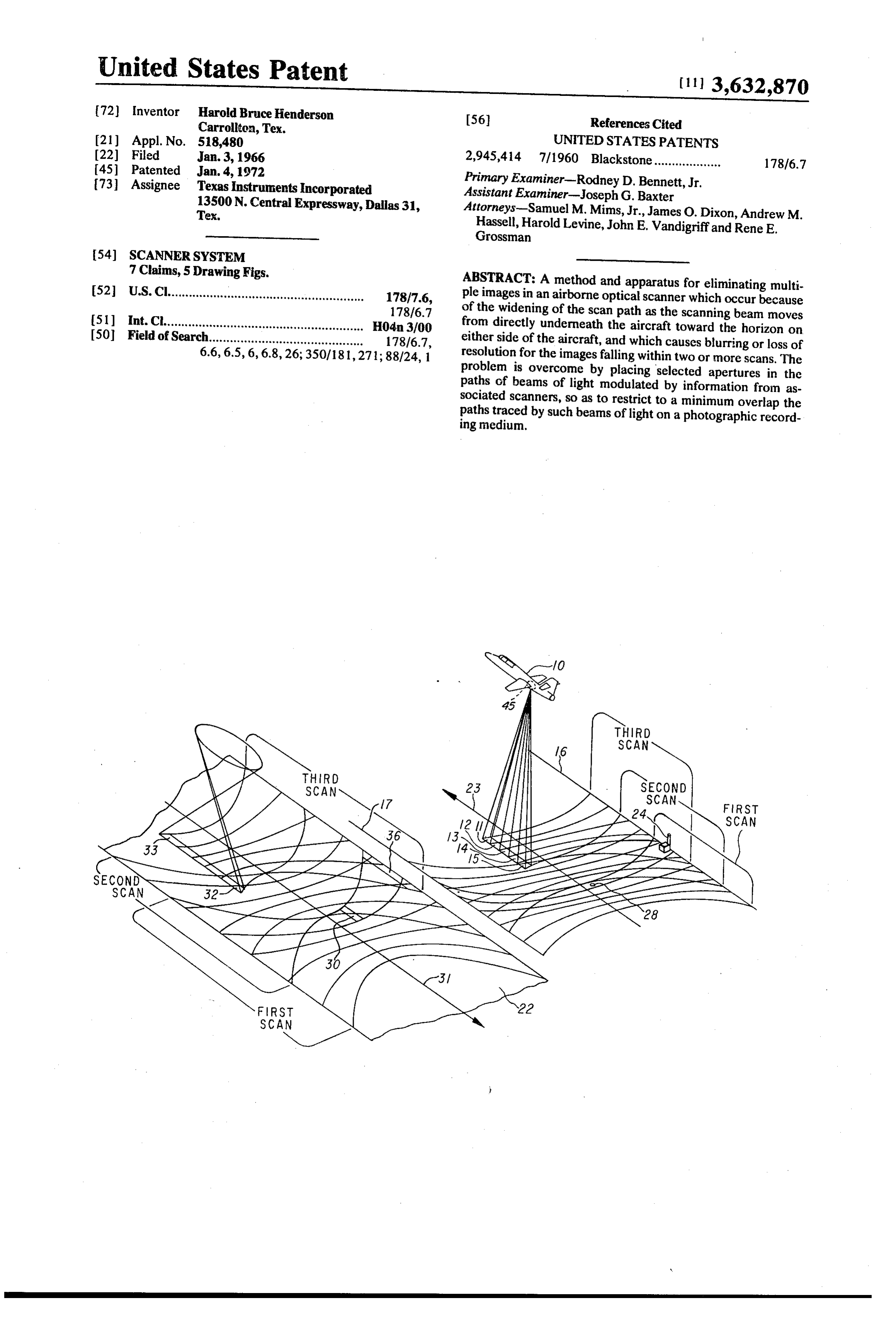
52 U.S. Cl........................................................ 178/7.6, ABSTRACT: A method and apparatus for eliminating multi ple images in an airborne optical scanner which occur because
(51) Int. Cl......................................................... H04m3/00 of the widening of the scan path as the scanning beam moves 50 Field of Search............................................ 178/6.7, from directly underneath the aircraft toward the horizon on either side of the aircraft, and which causes blurring or loss of 6.6, 6.5, 6, 6.8, 26; 350/181,271; 88/24, 1 resolution for the images falling within two or more scans. The problem is overcome by placing selected apertures in the paths of beams of light modulated by information from as sociated scanners, so as to restrict to a minimum overlap the paths traced by such beams of light on a photographic record ing medium.
Page 2
Drawing sheet — no readable text.
Page 3
Drawing sheet — no readable text.
Page 4
Drawing sheet — no readable text.
Page 5
Drawing sheet — no readable text.
Page 6
Drawing sheet — no readable text.
Page 7
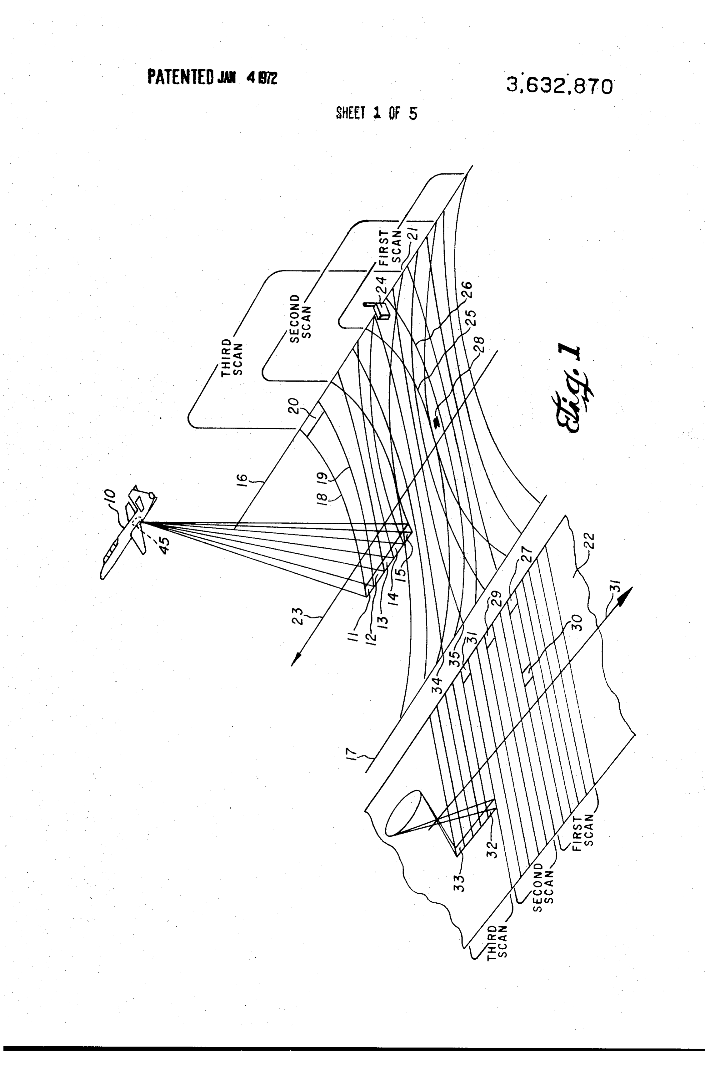
SCANNERSYSTEM Each of the detectors in the scanning array described has a This invention relates to an optical scanner and more par ticularly to such a scanner having a compensation for the fixed resolution. For example, each may have a resolution of 1.0 milliradian. That is, each detector can distinguish two fixed-axis resolution effect.
As an airborne optical scanner, for example an infrared much as objects radiating
as separate objects if they are separated by as milliradian. Accordingly, each detector is ar reconnaissance system, having constant angular resolution ranged with field stops so that it receives radiation only from scans the ground beneath the aircraft in a direction perpen the area encompassed by an angle of approximately 1.0X 1.0 dicular to the flight path, the terrain encompassed by the scan grows as the scan moves toward the horizon. This is the fixed milliradian. The problem solved by the invention arises from axis resolution (FAR) effect. With both single and multiple 10 the fact that such a fixed angle encompasses a much larger plot of terrain at large scan angles, i.e., near lines 16 and 17, detector reconnaissance systems, the FAR effect can cause than it does beneath the plane. Lines 18 and 19, representing the system to produce multiple display images of one target.
It is an object of the invention to compensate for the effect bound the area scanned by the first detector from line 16 to plot 11, offixed axis resolution. plot 20 which is the area encompassed by the same it is another object of the invention to provide an apparatus 15 angle as that which encompasses plot 11. This increase of scan and method for eliminating multiple display images of one tar area corresponding to the increase of the scan angle from the vertical is called the fixed-axis resolution effect or FAR effect.
get due to the fixed axis resolution effect in a multiple detector
Scale. The scan paths of the other detectors likewise being indicated Still another object of the invention is to provide an ap by boundary lines similar to lines 18 and 19, it can be seen that paratus for accurately displaying the images of targets de 20 the array as a whole observes a much larger area, bounded by tected by a multiple sensor infrared reconnaissance system. lines 18 and 21, at line 16 than beneath the plane. In accordance with the invention, the targets sensed by the The particular terrain patterns shown in FIG. 1 represent . reconnaissance system along a terrain path of variable width the special case in which the aircraft flies at a speed such that are displayed along a display path in the shape of the terrain each successive terrain scan pattern is tangential to the path, thereby eliminating multiple display images of the same 25 preceding scan pattern along the ground line 23 which target. represents the line of flight. The terrain scan patterns for each In a further aspect of the invention, there is provided an ap detector and for each of three successive scans are shown in paratus for displaying with FAR effect compensation, images FIG. 1, the outermost limit of the first, second, and third ter of targets detected by a multiple sensor infrared reconnais rain scan patterns being indicated by brackets. Although it sance system. 30 would be possible to allow a gap along line 23 between succes Other objects, features and advantages of the invention will sive scan patterns, such a practice would leave a portion of the be more readily understood from the following detailed terrain unobserved. It would also be possible, and is often the description when read in conjunction with the appended case, that each successive scan pattern overlaps the preceding claims and attached drawing, in which: scan pattern somewhat.
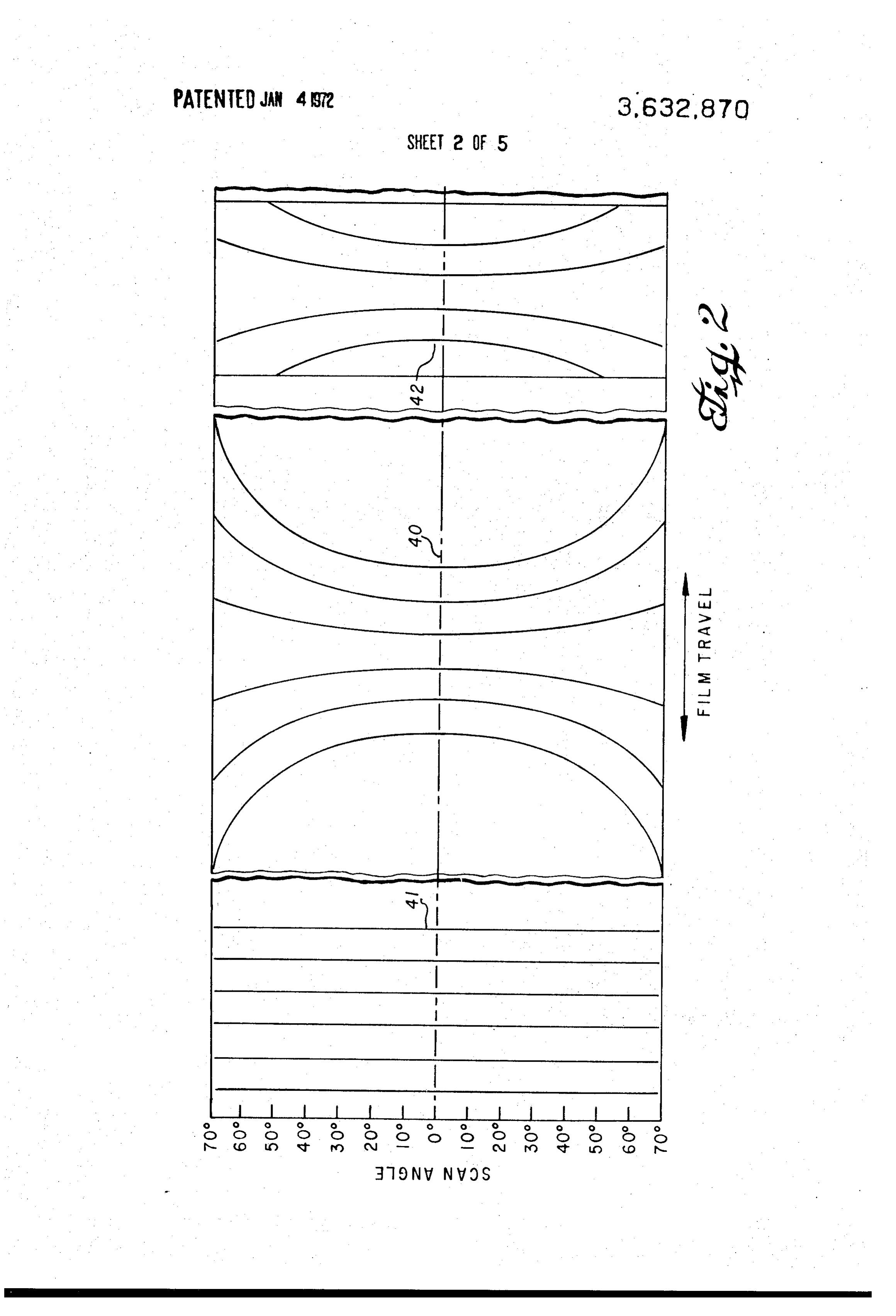
FIG. 1 illustrates the operation of a multiple detector in 35 The display problem resulting from the FAR effect can be frared scanning system without the compensation provided by appreciated from a consideration of the film record 22 of the the invention; detector outputs. On film record 22, the outputs of the five de FIG. 2 illustrates possible display paths for use with a multi tectors are recorded on five parallel paths transverse to the ple detector system; direction of film movement. The record of each detector out FIG. 3 illustrates the operation of a multiple detector in 40 put is made by a light modulator responsive to the electrical frared scanning system in accordance with one embodiment of output signal of one of the detectors. Thus, the output at film the invention; location 32 is from a modulator receiving an electrical signal FIG. 4 illustrates the operation of a multiple detector in from the detector which senses the infrared radiation at plot frared scanning system in accordance with a second embodi 15. Therefore, the brightness of the light projected on location ment of the invention; 45 32 corresponds to the intensity of the infrared radiation de FIG. 5 shows an apparatus for providing FAR effect com tected at plot 15. The film record at spot 33 likewise cor pensation according to the invention; and responds to plot 11. The light from the five light modulators is FIG. 6 illustrates a compensation mask for use with the ap moved across the film, exposing the film in accordance with paratus of FIG. 5. the amount of infrared radiation detected by the individual de FIG. 1 illustrates the problem solved by the invention. Air 50 tectors. The speed of scanning across the film in the direction plane 10 has several detectors 45 located therein for detecting transverse to its movement is in proportion to the speed ofter infrared radiation emanating from the terrain below the air rain scanning between lines 16 and 17. In the system of FIG. 1, craft. There are five such detectors in the case illustrated, the the light from the light modulators is applied to film record 22 detectors being arranged generally side by side in a line. A sin in such a manner that the film record for each detector has a gle-optical system casts an image of the terrain on the array of 55 constant width across the film, rather than exhibiting a "bow five detectors. Detectors and a scanning system suitable for tie' appearance similar to the terrain scan patterns. The film is such a reconnaissance system are found in the single detector moved with respect to the modulators as indicated by the RS-7 Infrared Reconnaissance System, manufactured by arrow 31. The speed of the film is controlled in accordance Texas Instruments Incorporated, Dallas, Texas. The scanning with the velocity and height of the aircraft, so that the succes and detecting system may be of the type illustrated for one of 60 sive scans of the modulators will be located with respect to the detectors shown in U.S. Pat. No. 3,069,493 issued Dec. each other in the same manner as the successive terrain scans. 18, 1962 to Bob Martel, with plural detectors and the field Each of the three sets of five parallel film records is seen to be stops required for each detector replacing said one detector. adjacent the next preceding set for the particular set of terrain At the instant shown in FIG. 1, the first infrared detector (or scans shown in FEG, 1.
sensor) is responsive to radiation from a plot of terrain 11. 65 On the first scan in FIG. 1, infrared radiating target 24 is de The second sensor detects radiation from plot 12, and the third, fourth, and fifth sensors are responsive to plots 13, 14 tected by the first detector, which scans a sector bounded by lines 25 and 26. Hence, an image 27 appears on the film and 15, respectively. At other times during the operation of record the detectors, the five plots scanned by the individual detec detector22oninthe a position corresponding to the output of the first first scan. A second target 28, nearer line 23, tors do not change in their general relationship to each other, 70 is detected and gives but the optical system associated with the detectors causes the the multiple detectorsrise to image 30. On the second scan of target 24 is detected by the third detec array of detectors to scan the terrain from line 16 to line 17. tor, scanning an area bounded by lines 34 and 35 and an image The sector observed by the array repeatedly sweeps from line 29 appears on the film record in the trace corresponding to 16 to line 17 along a path perpendicular to the line of flight, the third detector on the second scan. Target 28 is not de each new scan beginning again at line 16. 75 tected by any of the detectors on the second scan; hence no
Page 8
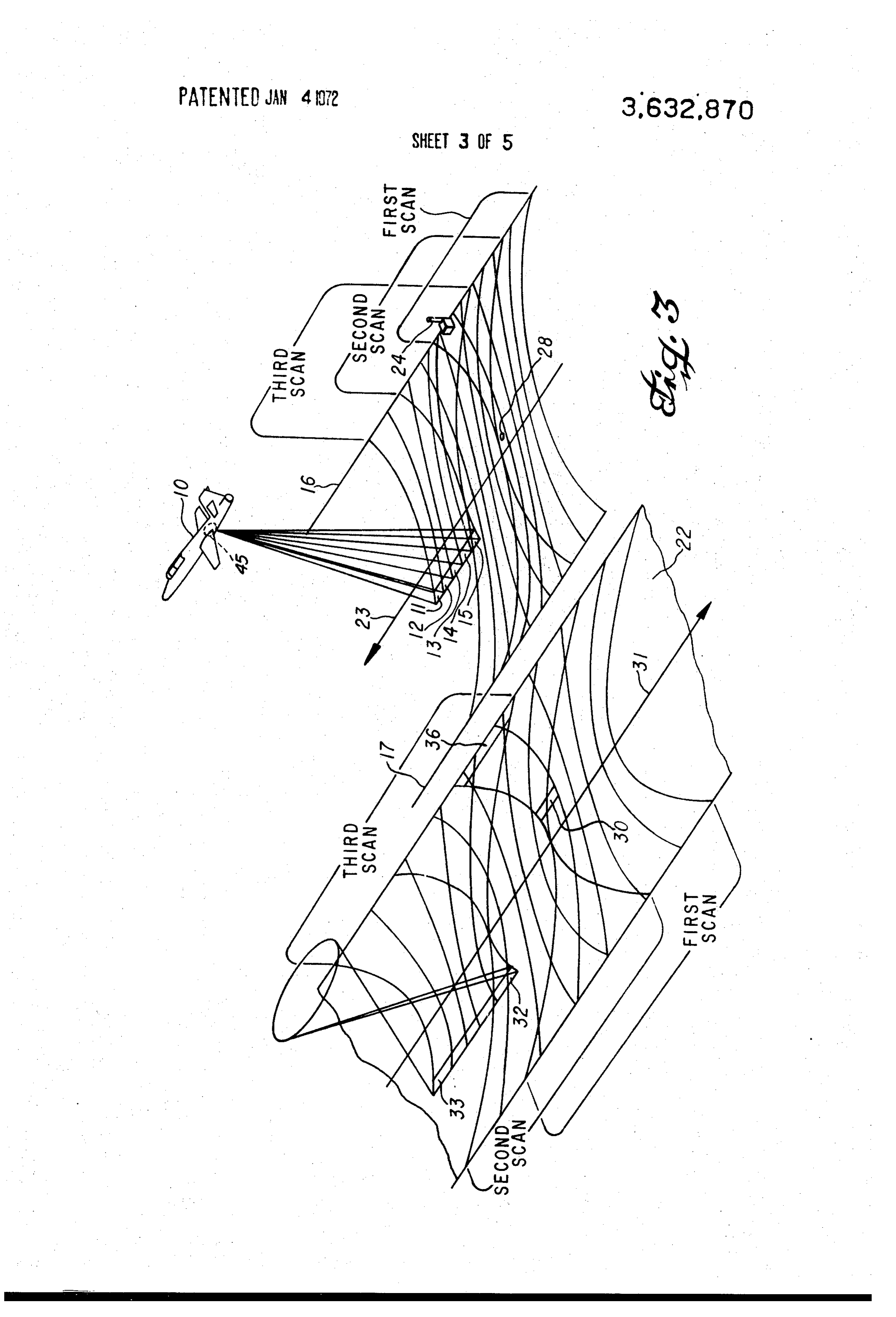
image thereof appears in the film record of the second scan. first detector for the first scan. The speed of the film 22 with Target 24 is detected by the fifth detector on the third scan, respect to the light modulator, as in the display of FIG. 1, is in and appears as image 31 on the film record. Target 28 is not such proportion to the velocity of the aircraft 10 that the suc detected by any of the detectors on the third scan. Thus, while cessive scans of the light modulators across the film 22 overlap a target such as target 28 on the flight line 23 appears but once or are adjacent to each other along the moving dimension of on the film record, target 24 at a large scan angle creates three the film to the same degree that the successive scans of the in images, images 27, 29 and 31. If the airplane 10 flies slower, so frared detectors overlap each other on the terrain. Thus, in that a scan by the detector array overlaps the preceding scan, FIG. 3 it is seen that the first and second scans of the light the film record 22 may contain even more images of target 24, modulators across film 22 form an overlapping pattern identi by allowing said target to be detected one or more times by 10 cal to that of the first and second infrared detector scans each of the five detectors, rather than merely by three of them as shown. It is apparent that the multiple images produced by across the terrain. It is the overlapping of the terrain scans which gives rise to multiple detections of one target. When the the multiple detectors are seriously detrimental to target target images are produced in an image pattern directly cor identification, even under the best reconnaissance condition, which
FIG 1.
is that using tangential successive scans as illustrated in tions result intoonly 15 responding the terrain scan patterns, the multiple detec one image. Multiple images result from the
In accordance with the invention, one target is made to ap paths multiple detections only when there are employed display pear as but one film record image despite the detection of the a film such as those in FIG. 1, which do not locate the image in position corresponding to the terrain position of the tar target by multiple detectors. It has been conceived in ac 20 get.
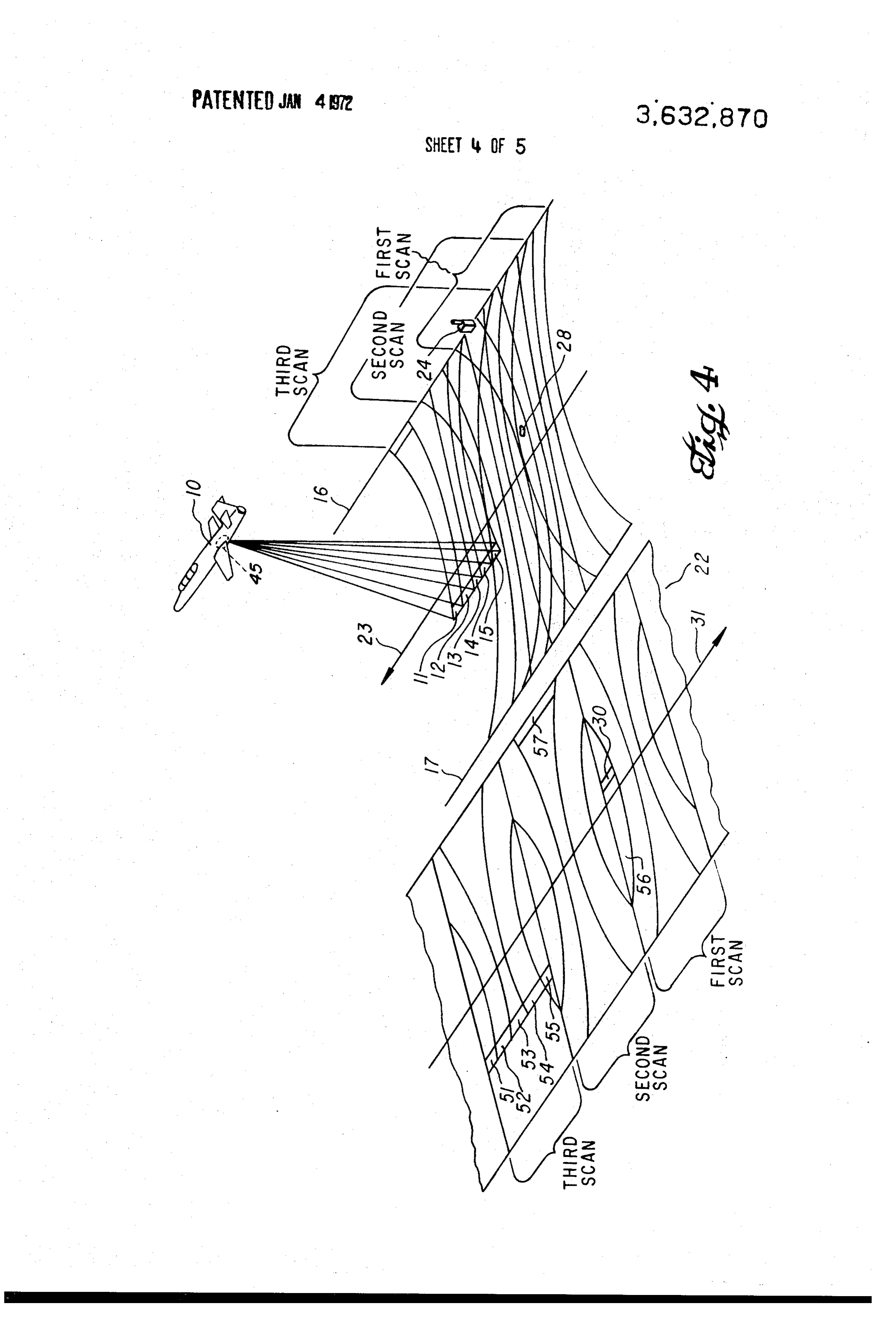
cordance with the invention that the foregoing can be accom On the third scan, in the display of FIG. 3, the fifth detector plished by causing the light modulators to expose the film senses target 24, and the corresponding light modulator prints record along paths having the same shape as the terrain sec an image of the target in the display path corresponding to the tors scanned on the ground. A first embodiment of the desired fifth detector. Again, the movement of film 22 in relation to film record scan is illustrated in FIG. 2 by the group of traces the light modulators causes the image of target 24 to be 40. For comparison, there is also included in FIG. 2 a film 25 printed on film 22 in the same position as image 36. Thus, de record scan 41 of the type shown in FIG. 1, wherein the light tection of target 24 on each of three successive scans result in from each modulator is traced straight across the film. The pattern of traces 40 causes each target detected to be placed but one display image 36. It is seen from FIG. 3 that the size of image 36 after multiple detections of target 24 may be on the film record in a position corresponding to its position 30 somewhat on the ground. As a result of such placement, the map created one of the larger than the size of the image produced by any light modulators, in response to one of the detec by the film record is directly analogous to the pattern scanned tions. This effect on the ground, and when a single target is detected by plural by a given target results can from the fact that the image produced vary, depending on which of the detec detectors, the motion of the film causes the plural images to be tors senses the target, and hence on which display path the tar printed out on top of each other as one image. Such operation get is printed. Moreover, it is seen is illustrated in detail in connection with FIG. 3. The third pat printed by a light modulator near theinedge FIG. 3 that the images of the film are large tern of traces 42 in FIG. 2 illustrates a second embodiment of in comparison to those printed near the invention. It is seen that the pattern 42 can be derived large in comparison to the images obtainable with the center of the film and from the pattern 40 by restricting the film images to an area of FIG. 1. Therefore, when it is said that the targetsthe display in the dis bounded by two straight, transverse lines tangential to the pat 40 play of FIG. 3 are placed in a film position corresponding to tern 40 at the portion thereof corresponding to the flight path the terrain position of the target, it must be understood that or zero scan angle. As will be described in connection with the accuracy of such placement is limited by the size of the FIG. 3, the effect of pattern 42 is to limit the number of image images corresponding to targets nearer the edge of the film. superpositions resulting from one target, with a commensurate The source of the large images near the edge of the film, is of improvement in image clarity. 45 course, the large terrain plot encompassed by the detectors at
FIG. 3 illustrates the film record obtained by using trace the pattern 40 of FIG. 2 in conjunction with the terrain scan pat withlarge scan angles. The display is merely producing images tern of FIG. I. An apparatus suitable for producing the curved Thus, the samethe accuracy as the detectors are sensing them. patterns 40 and 42 is discussed below in connection with 50 of FIG. 1 give a images small false near the edge of the film in the display appearance of accuracy when compared
FIGS. 5 and 6. The terrain and infrared detection system of
FIG.3 are the same as shown in FIG. 1 except that the outputs with the display of FIG. 3.
The terrain scan pattern illustrated in FIGS. 1 and 3, of the light modulators are applied to the film 22 of FIG. 3 wherein each terrain scan is tangential to the preceding scan along paths in the shape of pattern 40 in FIG. 2, rather than at the flight pattern 41 thereof, as used in the display of FIG. 1. Thus, the 55 the aircraft 10.path If 23, corresponds to one particular speed of aircraft 10 changes its speed, while maintain display image produced at locations 32 and 33 in FIG. 3 cor ing the same height and maintaining the same rate of scanning respond to terrain plots 15 and 11, respectively. The three in the direction transverse to the flight path, the successive groups of five display paths corresponding to the first, second terrain scans produced will be closer together or farther apart and third scans in FIG. 3 are indicated in the figure by than those shown in FIGS. 1 and 3. Nevertheless, the display brackets.
system of the invention operates in the manner described, to
For the display illustrated in FIG. 3, on the first scan, both 60 avoid targets 24 and 28 are detected by the first detector. Images of tions oftheone production of multiple images from multiple detec target. The particular case of FIGS. 1 and 3 has the two targets are correspondingly printed on film 22 as images 36 and 30, respectively. On the second scan, target 28 been shown merely for its comparative clarity of illustration. FIG. 4 illustrates the film record obtained by using trace is not detected by any of the detectors, hence, there is no 65 pattern image printed corresponding to that target. Target 24 is de FIG. 2, 42, the second embodiment of the invention shown in for the terrain scan pattern of FIG. I. As can be seen tected by the third detector in the second scan, and an image from FIG. 2, pattern 42 is just like pattern 40, except that por is produced in the display path corresponding to the third de tions of the four outer display paths are missing. The operation tector. The position on the film of the image printed in of a system response to the detection of target 24 by the third detector is 70 tion as theyusing pattern 42 is to print images in the same posi the same position as previously printed image 36. The two which wouldwould be printed in pattern 40, except that images be printed in the missing portion are not printed.
image locations coincide because the film 22 has moved with Apparatus for producing this operation is discussed in connec respect to the light modulators sufficiently that a portion of tion with FIGS. 5 and 6.
the display path corresponding to the third detector for the On the first scan illustrated in FIG. 4, targets 24 and 28 are second scan overlaps the display path corresponding to the 75 detected by the first detector, as previously described. How
Page 9
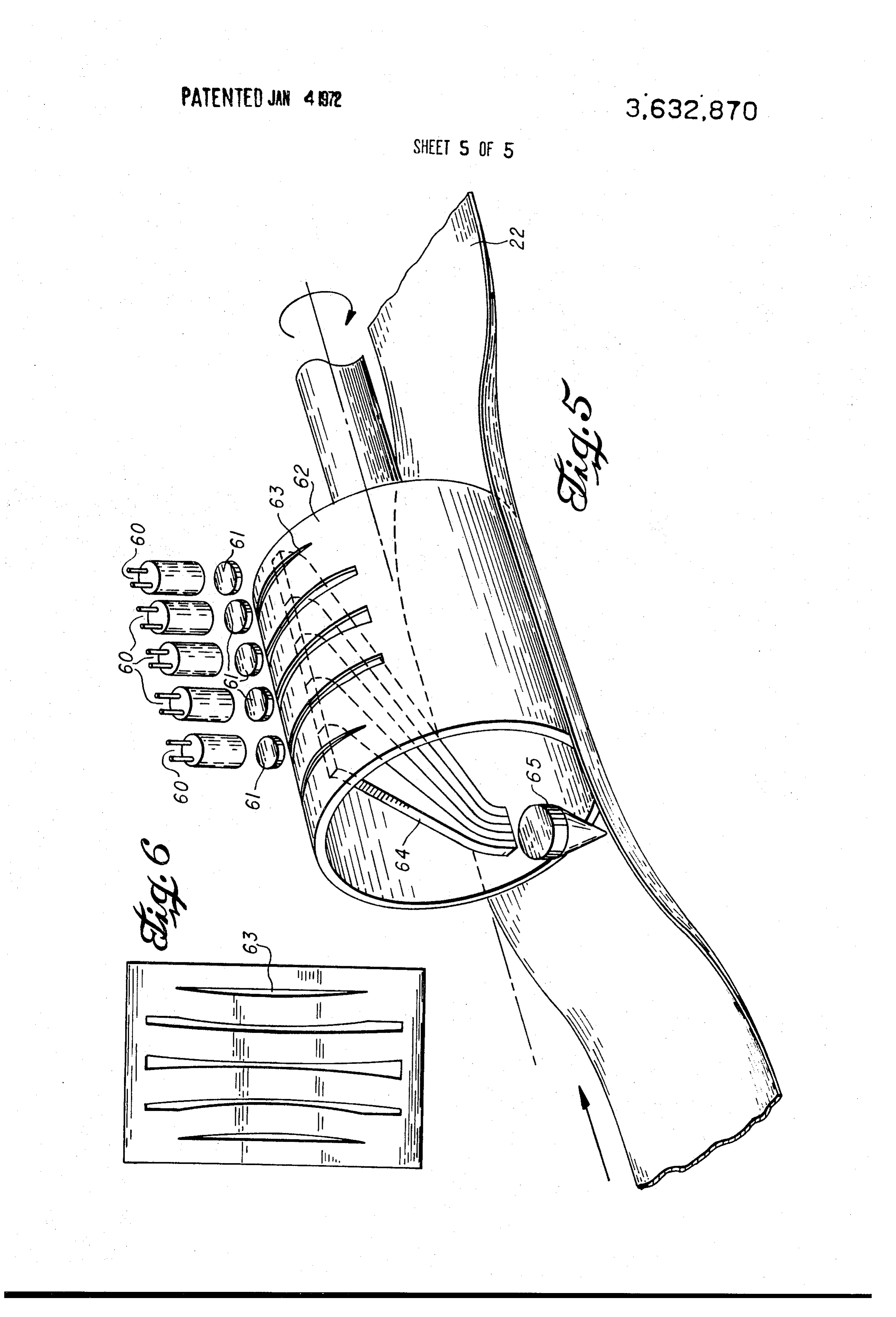
ever, the display space corresponding to the first detector is about the cylindrical axis thereof, the movement of limited to a small sector 56, there being no film area which microscope objective 65 across the film causes the image corresponds to the terrain sector for the first detector in which produced thereby likewise to sweep across the film in a target 24 is located. Hence, there is no image of target 24 direction transverse produced on the first scan. The image of target 28 falls within that shown in FIG. 6,tothe the movement of the film. If the mask is sector 56; hence it is printed as image 30. On the second scan, pattern 42 of FIG. 2. Theresulting trace pattern on film 22 is the third detector senses target 24 and an image 57 is printed. pends, of course, on the ratespeed of rotation of mask 62 de Target 28 is not detected on the second scan. On the third scans between lines 16 and 17atinwhich FIG. the five detector array 1. The speed of film 22 scan the fifth detector detects target 24, but again there is no display area corresponding to the terrain sector in which the 10 isFIG, controlled by the velocity and height of the aircraft just as in
fifth detector detects target 24; hence, no image is produced on the film record. There is also no image of target 28 useFiber optics bundle 64 has two major functions. First, the produced by the third scan. Thus, there is printed only one maskof62, the bundle makes possible the use of a mask such as image corresponding to each target, though the target be de apart, to wherein the openings 63 are spaced significantly far obtain a pattern, as pattern 42, where the images tected on successive scans, 15 produced by openings 63 are adjacent. Second, the tapering of
The difference between the images produced by film trace each optic channel in the bundle 64 causes the light to pattern 40 of FIG. 2 and those produced by pattern 42 in the emanate same figure is that the pattern 42 results in less overlap assuring from that the small end thereof at a wide dispersion angle, microscope objective 65 may travel through a between the images produced by one scan and those produced 20 rather wide arc as it traverses film 22 while still receiving light by the preceding scan. Thus, for the particularly favorable air from fiber optics bundle 64.
plane speed corresponding to the terrain scan pattern in FIGS. It is seen in FIG. 6 that the shape of the openings 63 is the 1, 3 and 4, the film images corresponding to successive scans same as that of the display paths in pattern 42. To produce the may be produced without any overlap. As seen in FIG. 3, the display pattern 40, the openings 63 are likewise constructed in scan images produced by pattern 40 for the same speed dis 25 the shape of the display paths in pattern 40. The shape of the play considerable overlap when printed out adjacent to one display patterns should in turn conform to the shape of the ter another at their narrowest point. It is to be emphasized that at rain scan patterns.
lower plane speeds, both patterns 40 and 42 produce an over If the apparatus of FIG. 5 is to produce a film record of lap of succeeding scan patterns and that in such cases, pattern frequently occurring successive scans, mask 62 may be 42 causes successively detected images of the same target to equipped with more sets of openings in the shape of openings be printed in superposition on the film, just as does pattern 40. 30 63 disposed about the cylindrical axis of mask 62. Each set of Yet pattern 42 produces less overlapping, because of its openings would have corresponding microscope objective, shape. Clarity of target identification is enhanced by the located diametrically opposite therefrom as in the case of ob decreased overlap, since the variation in the width of the jective 65. Such an arrangement would provide multiple scans images from the various detectors prevents perfect superposi 35 on each revolution of cylindrical mask 62 and would be par tion. ticularly suited to producing the film record for those scanners From the illustrations of FIGS. 3 and 4, it is seen that in the which perform the terrain scan by means of a rotating, mul reconnaissance system of the invention, there is provided tisided mirror as in the above-cited U.S. Pat. No. 3,069,493. means for sensing a condition, namely infrared radiation, It is to be understood that the above-described embodi along a terrain scan path. The width of the scan path is varying 40 ments are merely illustrative of the application of the princi because of the FAR effect. Further provided are means for ples of the invention. Numerous other arrangements may be representing the sensed infrared radiation along a display path devised by those skilled in the art without departing from the by exposing a film in accordance with the radiation detected. claims. spirit and scope of the invention as defined by the appended The exposure or display path on the film is made to have the shape of the terrain path to eliminate multiple images of one 45 I claim:
target. In the display of FIG. 4, only a portion of some terrain 1. A sensing method, comprising: sensing a condition along paths are represented by a display path. first and second scan paths during a first period and along Shown in FIGS. 5 and 6 is apparatus for correcting for FAR third and fourth scan paths during a second period, said fourth effect by the use of the patterns 40 and 42 of FIG. 2. FIG. 5 50 path overlapping said first path, and shows a masking device with openings 63, the shape of which representing the condition sensed on each of said scan paths determines whether pattern 40 or 42 is generated. Each of along a display path wherein multiple images resulting light modulators 60 in FIG. 5 is responsive to the output of one from only a single condition along said scan paths, due to of the five infrared radiation detectors in the scanning array. overlap from said varying widths of said scan paths, are The light from each modulator is collimated by a collimating 55 eliminated.
lens 61. A cylindrical compensation mask 62 rotates about its 2. The method of claim 1, wherein said step of sensing com cylindrical axis beneath the modulators 60. Compensation prisesresolution. detecting infrared radiation by scanning a surface with mask 62 is opaque except for openings 63 therein. FIG. 6 fixed 3. A sensor system comprising:
shows the shape of the openings 63 when compensation mask 62 is laid flat, the openings illustrated in FIG. 6 producing pat 60 first means for sensing a condition along a first scan path tern 42. Each of the openings 63 is positioned on the mask 62 during a first period and along a second scan path during to receive light from one of the modulators 60. Beneath the a second period, wherein the width of said first and said rotating mask 62 and stationary with respect to modulators 60 second scan paths varies in a direction perpendicular to is a fiber optics bundle 64. The bundle is composed of five the direction of said path, fiber optics channels, as shown, each channel being wide at 65 second means for sensing a condition along a third scan path during said first period and along a fourth scan path the end near modulators 60 and tapered to a small size at the during said second period, said fourth path overlapping other end. Each of the fiber optics channels is positioned to said first path, wherein the width of said third and said receive light coming through one of the openings 63. The light fourth scan paths varies in a direction perpendicular to thus received is transmitted from the smaller end of the chan the direction of said path, nel into a microscope objective 65. 70 third means responsive to said first and second means to Film 22, curved to conform to the cylindrical surface of represent the conditions sensed along each of said scan mask 62, moves parallel to the cylindrical axis of the mask. paths on a display path wherein multiple images resulting Microscope objective 65, which is fixed with respect to mask from only a single condition along said scan paths, due to 62, reduces in size the image received from fiber optics bundle overlap from said varying widths of said scan paths, are 64 and casts the reduced image on film 22. As mask 62 rotates 75 eliminated.
Page 10
4. The sensor system of claim 3, wherein said first and third means responsive to said first and second means to second means are fixed resolution infrared detector means for scanning a surface. represent the conditions senscd along each of said scan 5. A sensor system comprising: paths on a display path having the shape of the cor means for sensing a condition along a path whose width va- 5 responding scan path, said third means including ries in a direction perpendicular to the direction of said a moving film and light modulator means responsive to path, including a fixed resolution infrared detector means said first and second means to represent on said film for scanning a surface, and the radiation detected along each scan path on a cor means responsive to said means for sensing for representing responding display path, said film having means as the sensed condition along a display path in the shape of 10 sociated therewith for orienting said display paths ac said path of varying width, said means for representing in cording to the orientation of said scan paths by moving cluding said film with respect to said modulator means, and a moving film, masking means between said light modulator means and light modulator means responsive to said detector means to said film for producing each of said display paths in the shape of the corresponding scan path.
produce along a display path on said film a visible 15 7. An apparatus for causing plural light beams to scan paths representation of the detected infrared radiation, and masking means interposed between said modulator means having ing:
predetermined elongated shapes on a surface, compris and said film to produce said display path in a shape a mask having plural, spaced-apart openings, each opening which eliminates unwanted images detected by said being located in one of said light beams and each having sensing means. 20 one of said predetermined shapes, said masking having a 6. A sensor system comprising: motion relative to said beams in the direction of the elon first means for sensing a condition along a first scan path gation of said openings, during a first period and along second scan path during a plural, tapered fiber optic channels, fixed with respect to second period, said beams, each channel receiving at the larger end second means for sensing a condition along a third scan 25 thereof the light passing through one of said openings, path during said first period and along a fourth scan path and during said second period, said fourth path overlapping focusing means fixed with respect to said mask for directing said first path, w the light emitted by the smaller end of said channels onto said first and second means including fixed resolution in said surface.
frared detector means for scanning a surface, 30 : sk ck >k ck
Provenance
- Collection
- Cited prior art
- Original PDF
- patentimages.storage.googleapis.com →
- Filed
- 1966-01-03
- Pages
- 10
- Method
- pdftotext (the PDF's own text layer) + pdftoppm 300dpi page scans
- Source
- Google Patents bibliographic record
- Granted
- 1972-01-04
- Inventors
- Harold Bruce Henderson; Texas Instruments Inc
- Transcribed from
- patentimages.storage.googleapis.com →