patent · US5338421
Method of and apparatus for separation by agglomeration
16 August 1994
Page 1 — bibliographic record
United States Patent (19) 11 Patent Number: 5,338,421 Abe et al. 45 Date of Patent: Aug. 16, 1994 (54) METHOD OF AND APPARATUS FOR 4,409,078 10/1983 Wagner et al. ..................... 2O4/88 SEPARATION BY AGGLOMERATION 4,602,989 7/1986 Culkin .............................. 204/180.1 (75) Inventors: Naoki Abe, Okazaki; Fumio FOREIGN PATENT DOCUMENTS Kawahara, Toyota; Noboru Inoue, 58-156309 9/1983 Japan .
Osaka, all of Japan 4-59002 2/1992 Japan .
73) Assignees: Toyota Jidosha Kabushiki Kaisha; Primary Examiner-John Niebling MEC International Corporation, both Assistant Examiner-Arun S. Phasge of Toyota; Zeotek LRC Corporation, Attorney, Agent, or Firm-Oliff & Berridge Osaka, all of Japan
A method of separating an aqueous colloidal solution by 22 Filed: Aug. 2, 1993 agglomeration into water and agglomerate of colloidal (30) Foreign Application Priority Data particles by applying voltage to the aqueous colloidal solution to promote the agglomeration of colloidal par
Aug. 7, 1992 JP Japan w wa w aw w8 was a w w so u a a 4-2850 ticles. The frequency of the voltage to be applied to the Jul. 8, 1993 JP Japan .................................. 5-169008 aqueous colloidal solution is increased to about 10 kHz 51) Int. C. .............................................. CO2F 1/463 to improve efficiency of agglomeration and suppress 52 U.S. C. .................................... 204/186; 204/188; electrolysis of water. As the frequency is increased, 204/191; 204/275; 204/302 hydrogen is generated earlier than the reaction of oxy 58) Field of Search ............... 204/149, 186, 188, 191, gen generated by the electrolysis of water with the 204/302, 275 colloidal particles, thus not oxidizing the colloidal parti 56) References Cited cles. Further, as the frequency is increased, the colloidal particles tend to obtain a greater oscillation energy, thus
4,033,851 7/1977 Oros .................................... 204/302 4,391,698 7/1983 Wagner ............................... 204/302 7 Claims, 6 Drawing Sheets
15 16 -f- 17 6
HIGH FREQUENCY WOLTAGE CURRENT
SIGNAL GENERATOR AMP L I FI ER AMP L I FI ER
CURRENT
CONTROL
C RCUIT
Page 2
Drawing sheet — no readable text.

Page 3
Drawing sheet — no readable text.
Page 4
Drawing sheet — no readable text.
Page 5
Drawing sheet — no readable text.
Page 6
Drawing sheet — no readable text.
Page 7
Drawing sheet — no readable text.
Page 8
tion, which at least comprises the steps of accommodat
METHOD OF AND APPARATUS FOR ing the aqueous colloidal solution in a tank provided SEPARATION BY AGGLOMERATION with a pair of electrodes and then applying a high fre quency voltage between the pair electrodes, the fre
BACKGROUND OF THE INVENTION 5 quency of the high frequency voltage being set to be at 1. Field of the Invention least a frequency at which polarity inversion occurs This invention relates to a method of and an appara earlier than generation period oxygen generated with tus for separating water and agglomerate of colloidal energization reacts with the colloidal particles. particles in an aqueous colloidal solution with colloidal The voltage of the high frequency voltage is set to be particles dispersed in liquid mainly composed of water, no higher than a voltage at which the substantial elec such as alkali washing liquid with oil dispersed in water trolysis of water is suppressed. The substantial electrol in the form of oil-drop-in-water emulsified particles in ysis of water refers to electrolysis that proceeds during water. By the term "colloidal particles” is meant either a time interval of one cycle or more of the high fre or both of liquid particles (i.e., emulsified particles) and quency voltage.
solid particles (i.e., hydrophobic colloidal particles). By 15 Desirably, an insulator is interposed between elec the term 'agglomeration” is meant gathering of parti trodes such that the current flowing through the aque cles into a greater particle. Where colloidal particles are ous colloidal solution is lower than the substantial water dispersed in an aqueous solution, by the term 'separa electrolysis suppression current.
tion to water and colloidal particles' is meant separa Also, the invention provides an apparatus for separa tion to aqueous solution and agglomerate of colloidal 20 tion by agglomeration, which is for carrying out the particles. method according to the invention and which com 2. Prior Art prises a tank for accommodating an aqueous colloidal It is well known in the art that a system in which water is dispersed in oil can be separated into water and solution, tank, and at least one pair of electrodes disposed in the a power source for applying a high frequency oil with application of a voltage to the system, as dis voltage between
the electrodes, the frequency of the closed in, for instance, U.S. Pat. Nos. 4,391,698 and power source being at least a frequency at which polar 4,409,078. These prior art literatures also disclose a technique of applying an AC voltage and also that effi tioninversion ity period occurs earlier than the reaction of genera oxygen generated by energization of the cient separation is obtainable with application of a volt system with the colloidal particles. age of 2 to 100 KV at a frequency of 60 to 1,500 Hz. 30
Similar techniques are also disclosed in Japanese Laid electrolysis of water is caused. between When a voltage is applied the electrodes,
Open Patent Publication No. 58-156309. In this tech an AC voltage, whenever the polarity of the voltage If the applied is nique, commercial power of 60 to 120 V (at 50 to 60 Hz) inversed, oxygen and hydrogen are generated alteris voltage is applied to colloidal solution.
The above disclosed techniques are for processing 35 nately from one electrode. If the frequency is one as systems in which water is dispersed in solution mainly used in the prior art, i.e., of the order of several 10 Hz composed of oil. Oil has low electric conductivity com to 1 kHz, the generated oxygen is reacted with colloidal pared to water, and current caused through oil is low particles, thus disabling recovery thereof in a satisfac even by applying comparatively high voltage. Besides, tory state. However, as the frequency is further in there is no problem of electrolysis of oil content. Thus, creased, oxygen and hydrogen are generated alternately efficient separation is obtainable by application of com in a very short period of time, and eventually hydrogen paratively high voltage. is generated earlier than the reaction of the generated However, where oil or the like is dispersed in water, oxygen with colloidal particles, thus making the reac currentis readily caused because water has high electric tion between oxygen and colloidal particles difficult. conductivity compared to oil. Therefore, if the voltage 45 Consequently, a state substantially free from the elec applied is increased to promote the separation, a high trolysis of water is obtained. This phenomenon was voltage high current is caused to result in shortage of discovered by the inventor, and the present invention is the capacity of the power source. Besides, because of predicated on this discovery.
the high current caused, electrolysis of water takes More specifically, if the frequency of the high fre place. When the electrolysis of water occurs, colloidal 50 quency voltage is set to be above a frequency at which particles of oil or the like are oxidized by oxygen that is polarity inversion occurs earlier than the reaction of generated, so that they can not be recovered in a satis generation period oxygen generated by energization factory state. At present, therefore, a method of separa with colloidal particles, voltage application to colloidal tion of an aqueous colloidal solution to water and colloi particles is possible with the electrolysis substantially dal agglomerate with voltage application does not pro 55 suppressed, thus lowering the surface potential on the vide for satisfactory results. colloidal particles and facilitating the agglomeration thereof.
SUMMARY OF THE INVENTION Further, if the voltage is set to be no higher than the An object of the invention is to provide a method of substantial water electrolysis suppression voltage, the promoting the separation of an aqueous colloidal system 60 substantial electrolysis of water is suppressed. Besides, mainly composed of water by applying a voltage to the even under this condition, the agglomeration proceeds system, which permits satisfactory separation results to Smoothly.
be obtained and also permits substantial suppression of Further, with an insulator provided between the elec the electrolysis of water. trodes to suppress current through the colloidal solu To attain the above object, the invention provides a 65 tion, the electrolysis of water can be suppressed effec method of separating an aqueous colloidal solution into tively.
water and agglomerate of colloidal particles by promot Further, with an apparatus which comprises a tank, ing the agglomeration of colloidal particles in the solu electrodes and a power source and in which the power
Page 9
source frequency is set to be at least a frequency at from the bottom of the tank 1 and having a small height. which the polarity inversion occurs earlier than the Process liquid after separation overflows from the elec reaction of generation period oxygen generated with trode chamber 4 over the partitioning plate 7 into the energization with colloidal particles, the agglomeration partitioned chamber 8.
of colloidal particles proceeds rapidly in a state in The end wall of the tank 1, i.e., a wall of the parti which the substantial electrolysis of water is suppressed. tioned chamber 8, has a lower portion formed with an BRIEF DESCRIPTION OF THE DRAWINGS out-flow port 11. An out-flow duct 10 is connected to the out-flow port 11. The out-flow duct 10 rises from
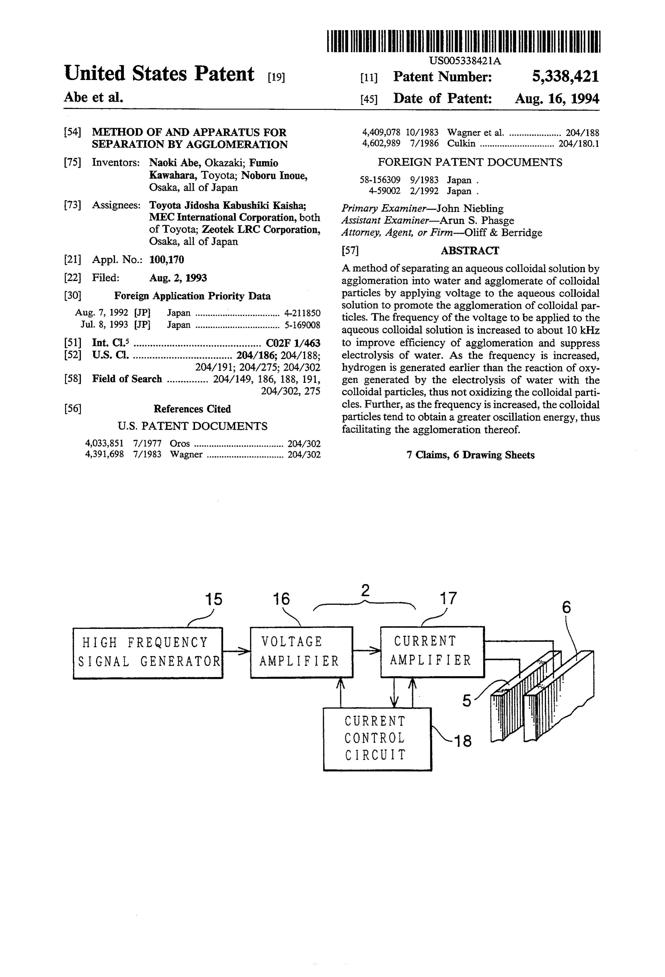
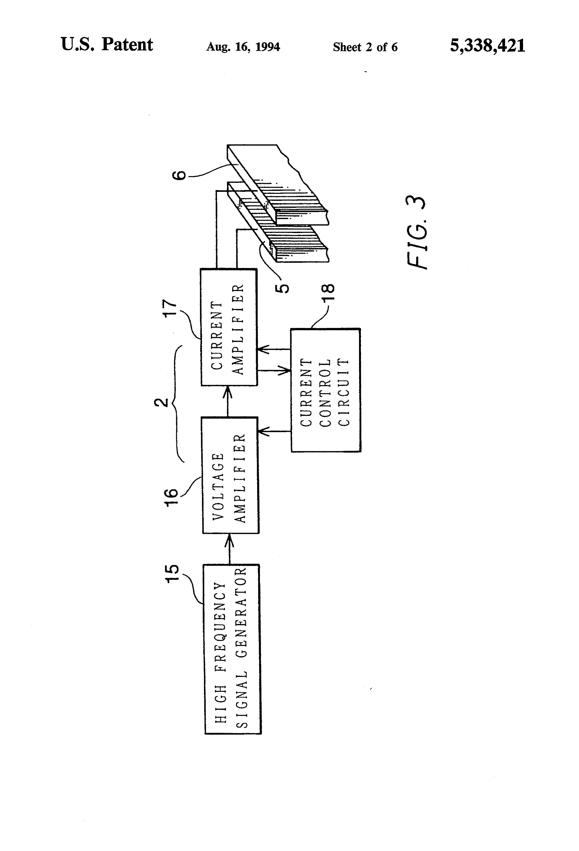
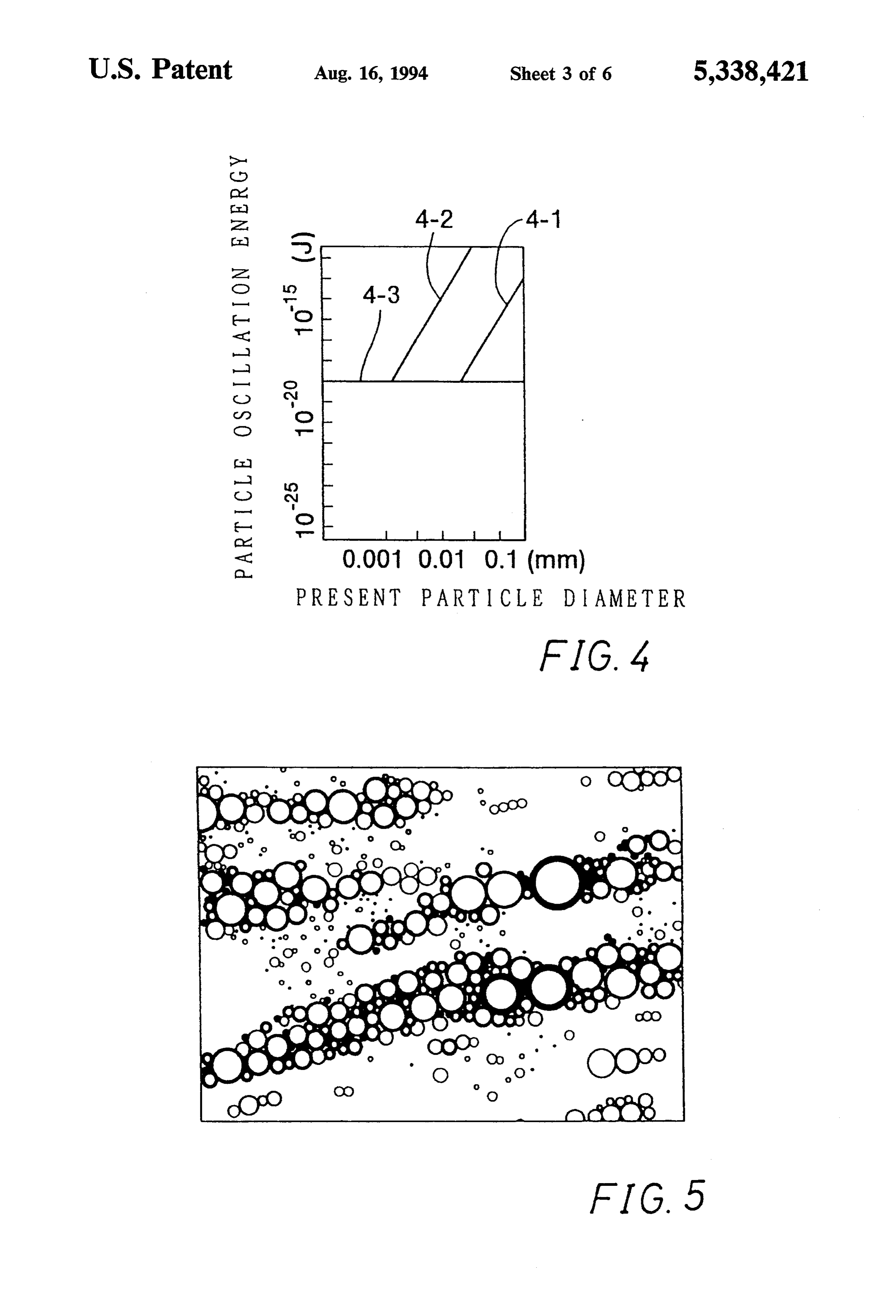
FIG. 1 is a vertical sectional view showing a first the out-flow port 11 up to the liquid level, and over embodiment of the apparatus for separation by agglom O flown process liquid flows out from the liquid level. eration; As shown in FIG. 3, the power source 2 includes a FIG. 2 is a transverse sectional view showing the high frequency signal generator 15 for generating a same apparatus; high frequency signal, a voltage amplifier 16 for receiv FIG. 3 is a block diagram showing a power source; ing and voltage amplifying a high frequency signal FIG. 4 is a graph showing the relationship among the 15 outputted from the high frequency signal generator 15, oscillation energy, repulsive energy, particle diameter a current amplifier 17 for current amplifying the signal and frequency;
FIG. 5 is a view showing an example of agglomerated outputted from the voltage amplifier 16, and a current control circuit 18. The outputside of the current ampli particle groups;
fier 17 is connected to the electrode plates 5 and 6 in the
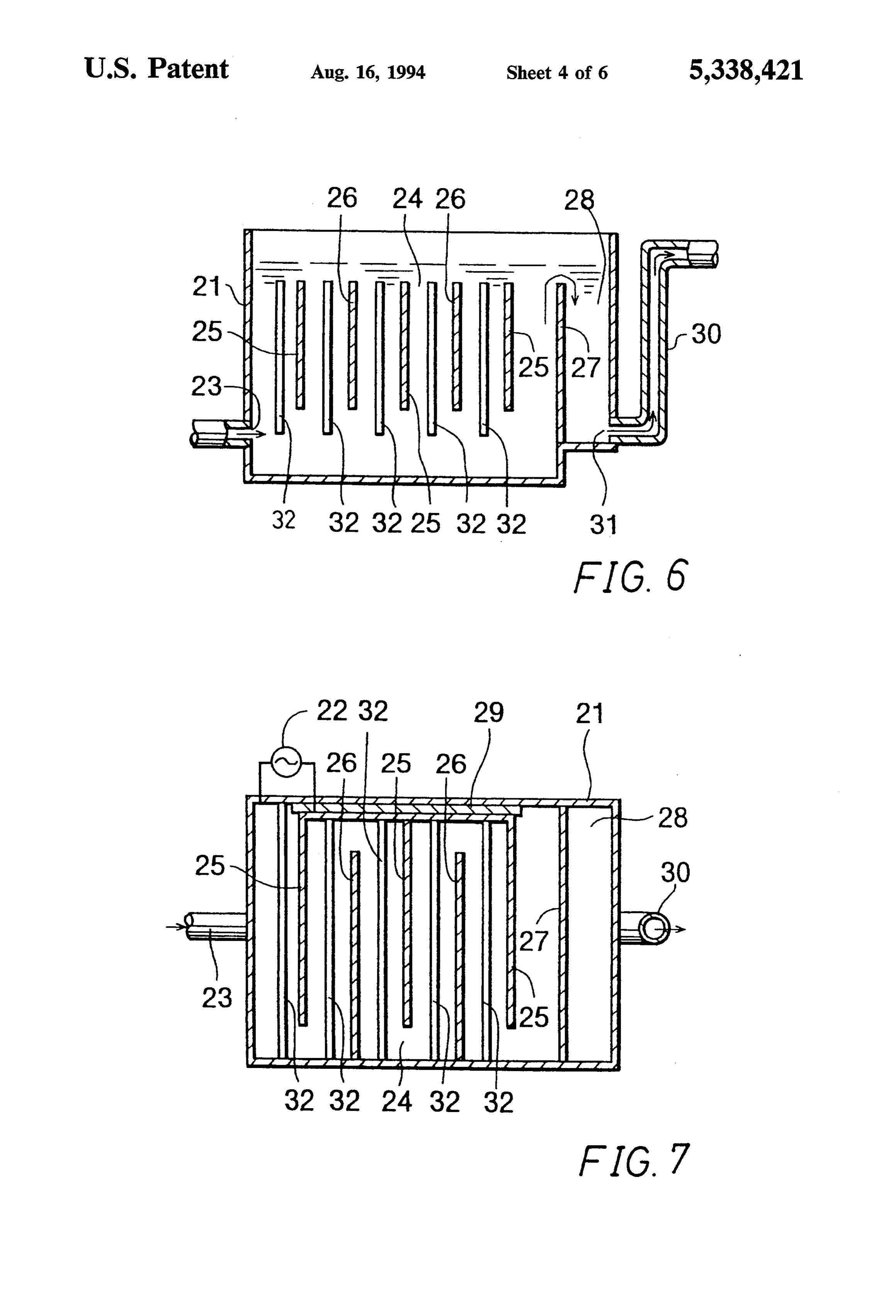
FIG. 6 is a vertical sectional view showing a second 20 electrode chamber embodiment of the apparatus for separation by agglom The high frequency signal generator 15 includes a eration;
FIG. 7 is a transverse sectional view showing the quency signal at oscillator high frequency for generating a high fre about 1 to about 500 kHz, and it can
Same apparatus;
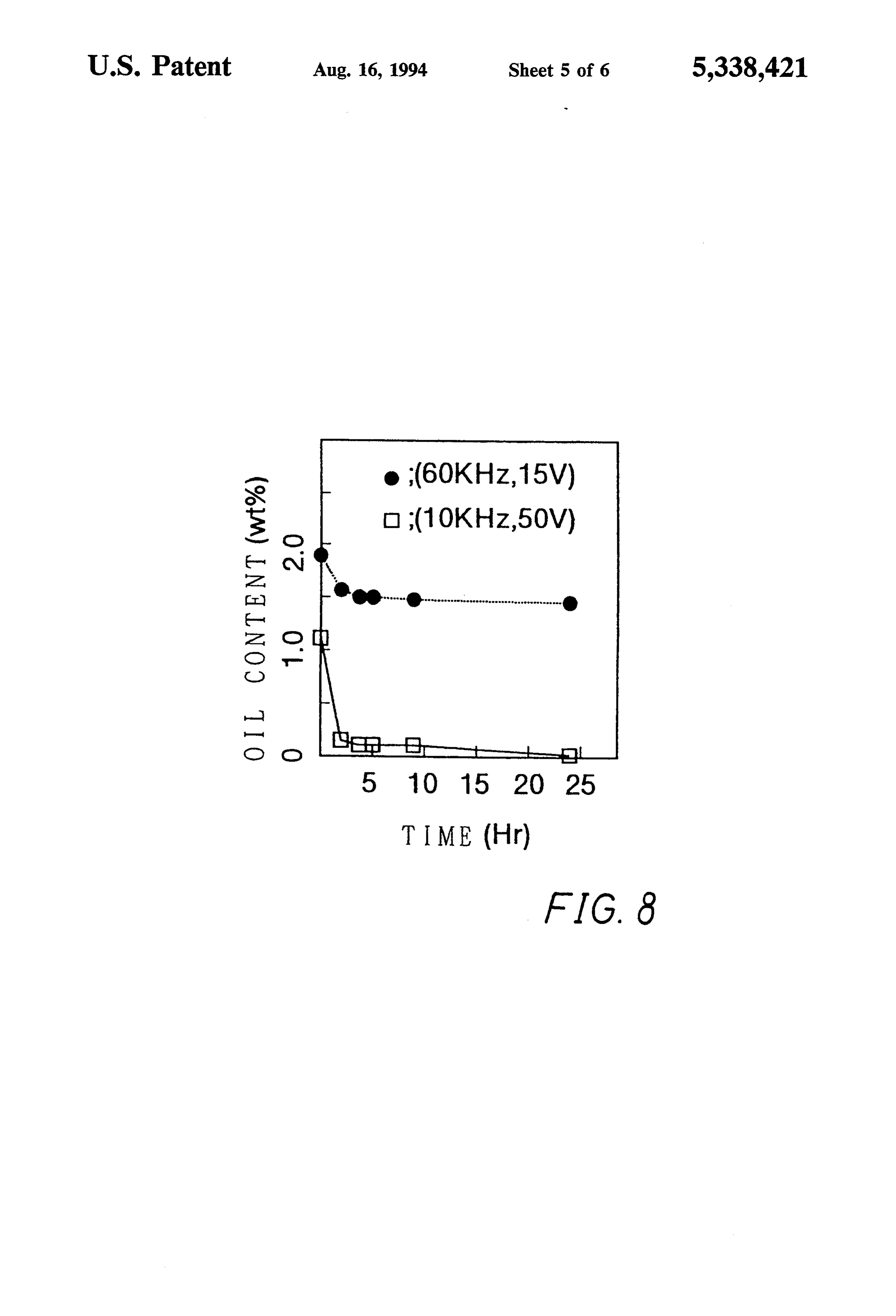
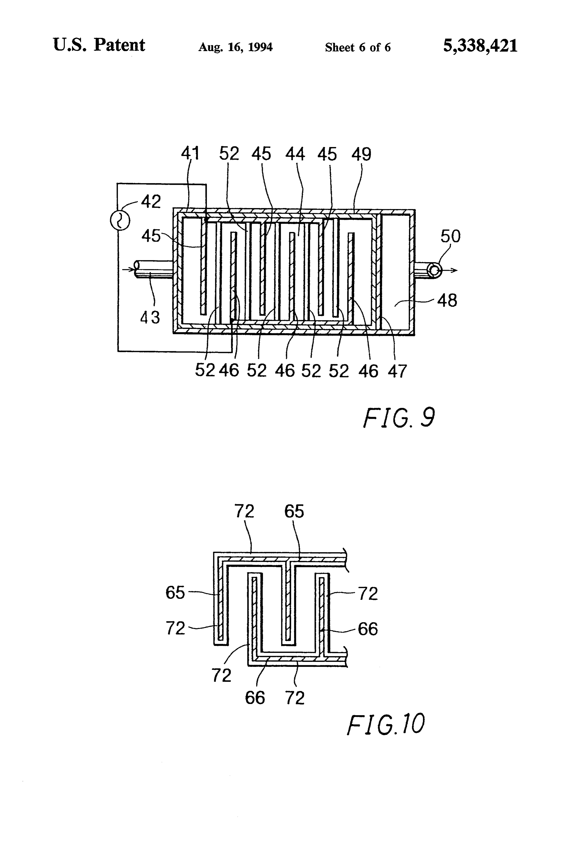
FIG. 8 is a graph showing the result of process car 25 set output a frequency signal at a frequency which can be ried out with the second embodiment; as desired. The high frequency signal generator 15 FIG. 9 is a transverse sectional view showing a third includes a sinusoidal, a rectangular and a sawtooth embodiment of the apparatus for separation by agglom wave output circuit for outputting a sinusoidal, a rect eration; and angular and a sawtooth wave, respectively, as high FIG. 10 is a transverse sectional view showing elec 30 frequency signal of oscillation. These output circuits are trode plates according to a fourth embodiment of the capable of being switched over to one another to output invention. the high frequency wave signal having the selected waveform.
DETAILED DESCRIPTION OF THE When waste liquid or like process liquid is put into PREFERRED EMBODIMENTS 35 the tank 1 and agglomeration processed by applying an Some preferred embodiments of the invention will electric field, the conductivity of the liquid is changed now be described. with the progress of agglomeration of particles. Due to the conductivity changes, the current flowing between
FIRST EMBODIMENT the electrode plates 5 and 6 is deviated from the current FIG. 1 is a vertical sectional view showing a first 40 value corresponding to the best agglomeration effi embodiment of the apparatus for separation by agglom ciency. Accordingly, the current control circuit 18 is eration, and FIG. 2 is a transverse sectional view of the provided for controlling the output current from the same apparatus. The apparatus comprises a tank 1, elec current amplifier 17.
trode plates 5 and 6 disposed in the tank 1 and a power The current control circuit 18 detects the output source 2 for applying a high frequency voltage between 45 current from the current amplifier 17 and compares the the electrodes 5 and 6 to apply an electric field to the detected current to a preset current value. If the com process liquid. pared current values are different, the circuit 18 outputs The tank 1 has a wall provided with a supply port 3 a voltage regulation signal to the voltage amplifier 16 for supplying process liquid thereto. A supply tube is for voltage regulation to match the output current of connected to the supply port 3. An electrode chamber 4 50 the current amplifier 17 to the preset current value. The is defined in the tank 1 near the supply port 3. In the current amplifier 18 also serves as a protection circuit electrode chamber 4, a plurality of opposite polarity for cutting the output of the current amplifier 17 in the electrode plates 5 and 6 are arranged alternately in a event of abnormal rise of the load current due to a vertical row. short-circuit between electrodes or like cause. The electrode plates 5 are secured via an insulating 55 In operation, waste liquid (with fine solid particles plate 9 to a wall of the tank 1, while the electrode plates dispersed therein) discharged from a washing step in the 6 are secured directly to the tank 1. Thus, the wall of the coating step, for instance, is supplied through a pump or tank 1 is held at the same potential as the electrode the like and the supply port 3 into the electrode cham plates 6. Thus, in the embodiment of FIGS. 1 and 2, six ber 4 in the tank 1. An agglomerate separation process electrode pairs are formed in the tank 1. Adjacent the 60 is started by starting the power source 2 and thus apply free ends of the electrode plates 5 and 6, a space is ing a predetermined high frequency voltage between formed which serves as a process liquid passage. In a the electrode plates 5 and 6.
bottom portion of the electrode chamber 4 in the tank 1, The frequency of the high frequency voltage applied a space is formed for collecting an agglomerated precip between the electrode plates 5 and 6 is set to be above itate. The electrode plates 5 and 6 are made of iron, 65 a frequency at which polarity inversion takes place aluminum or like conductive metal. earlier than the oxidization of the minute solid particles Adjacent the electrode chamber 4, a partitioned dispersed in the liquid by generation period oxygen chamber 8 is defined by a partitioning plate 7 extending generated by the energization. Since the frequency
Page 10
varies with the kind of the liquid and particles, it is progressive agglomeration of particles in the voltage determined by experiments in advance. application directions.
An example of experiment will now be described. As shown above, in this embodiment the particles Three different dispersing media for colloidal solution, acquire high oscillation energy and are readily agglom i.e., 0.01, 0.1 and 1% aqueous solutions of sodium sul erated with neutralization of the dual structure of the fide, were prepared. Also, the distance between the boundary electricity. Further, it is possible to obtain a electrode plates 5 and 6 was set to 15 mm, and a voltage phenomenon that metal ions flowing out from the elec of 20 volts was applied between the electrodes. Then, trode plates 5 and 6 react with hydroxide ions in the potassium iodide and starch solution was added to the liquid to form flocks which are precipitated by trapping tank, and a check was done as to whether oxygen is 10 particles.
generated by electrolysis of water and acts on iodine to The process liquid after separation of particles, over cause an iodine starch reaction. This check substantially flows over the partitioning plate 7 into the partitioned permits a check as to whether electrolysis takes place. chamber 8 and thence flows out through the out-flow By applying 60 Hz between the electrodes 5 and 6, duct 10. The agglomerated precipitate in the bottom of clear coloring was recognized with all the solutions (of 15 the 0.01, 0.1 and 1%). By increasing the frequency, the afterelectrode the chamber 4 is discharged in a suitable way process.
coloring was still recognized at 600 and 1,000 Hz al Where the process liquid is a water-soluble cutting or though there was a trend for color shading. When the washing frequency was increased up to 10 kHz, the coloring was containedliquid, a great amount of surface active agent is together with oil component in the liquid no longer recognized at all with all the solutions (of 20 which is mainly composed of water, the oil component 0.01, 0.1 and 1%). More specifically, with application of being contained as emulsion, i.e., as minute oil drops. a high frequency voltage at 10 kHz or above, hydrogen When this liquid is put into the tank 1 and a high fre was generated earlier than a reaction taking place be quency voltage is applied, the dynamic potential on the tween the generated oxygen and iodine, the generated interface of the oil component in the liquid is neutral hydrogen prohibiting the reaction between the oxygen ized by the electric field to promote agglomeration
and iodine.
Thus, where the dispersing medium is sodium sulfide the oil drops. As a result, the separated oil is floated up aqueous solution, by applying a high frequency wave at in the electrode chamber 4 to form a high oil concentra 10 kHz or above, it is possible to cause an electric field tion surface layer, while the lower layer is substantially to act on colloidal particles in a state that the oxidization 30 oil free water, thus obtaining the separation of the pro of these particles is suppressed. The substantial electrol cess liquid. Thus, even oil component in an emulsified ysis suppression frequency varies with the character of waste tion liquid can be separated efficiently by agglomera separation.
the liquid and colloid. Specifically, a frequency of 1 kHz as applied in the prior art is insufficient, and suffi EXPERMENT EXAMPLE ciently higher frequency has to be applied. 35
By applying a frequency of 10 kHz, the colloidal To confirm the effects of the above embodiment, an particles are oscillated at 10 kHz. The inventors con emulsified sample waste liquid was produced by adding firmed, as a result of observation of particles with an four liters of oil in 90 liters of commercially available optical microscope, a phenomenon that the particles alkali washing solution, and was subjected to an ag oscillate in the direction of voltage application. As a glomeration separation process in the present apparatus result of the oscillation, the particles acquire oscillation by applying a high frequency voltage of 60 kHz. After energy. FIG. 4 shows the oscillation energy for which the process, the amount of hexane extract from the the ordinate is taken, while taking the abscissa for the sample was measured.
particle diameter. This oscillation energy is in a case Table 1 shows the result of measurement. The mea when the oscillation amplitude is 1/10 of the particle 45 surement was carried out in conformity to JIS-K0102 diameter. The higher the oscillation energy is the higher (24-2). The table also shows the result of measurement the higher the frequency is. A plot 4-1 in FIG. 4 is for in a comparative example in which a commercial AC oscillation at 60 Hz, and a plot 4-2 for oscillation at 60 electric field at 60 Hz was applied to the sample waste kHz. liquid.
Shown at 4-3 is the level of repulsive energy of parti 50 TABLE 1 cles. When the oscillation energy of particles surpasses the repulsive energy, the particles can be agglomerated. Hexane extract quantity (mg/liter) Number of
As is seen from FIG. 4, at a frequency of 60 Hz, the times of Experiment example Comparative example agglomeration can not be obtained unless the particle circulatory (frequency of (frequency of diameter is 0.01 mm or above, whereas at a frequency of 55 process electric field: 60 kHz) electric field: 60 Hz) 60 kHz particles greater than 0.001 mm can be agglom O 16,000 16,000 erated. 6 10,000 13,000 According to the invention, a frequency at which 12 9,000 1,000 substantial electrolysis of water is suppressed is used, 24
and thus the agglomerating capacity can be improved at the same time.
FIG. 5 shows the result of actual observation of ag From the above experiment, it will be seen that when glomerated particles as a result of the process in this agglomeration separation is carried out with the em embodiment. In FIG. 5, to the left and right are direc bodiment of the apparatus by applying a high frequency tions of voltage application. It is recognized that parti 65 voltage, a greater amount of oil component can be re cles oscillated in transverse directions and that the duel moved by separation from the sample liquid compared structure of boundary electricity in the transverse posi to the case of applying a commercial AC power source tion of the individual particles is neutralized to obtain voltage.
Page 11
As for the current and voltage of high frequency In either of the above embodiments, a comparatively power applied to the waste liquid, with a waste liquid low voltage is applied between electrodes. Thus, the containing solid particles, the best result of agglomera electrolysis of water hardly takes place. Besides, since a tion separation solid particles, the best result of agglom high frequency voltage is utilized, the electrolysis of eration separation could be obtained by applying a high water substantially does not take place. frequency wave power to the electrode plates such that As has been shown in the foregoing, according to the the frequency was 60 kHz, the current was 0.9A and invention the agglomeration of colloidal particles is the voltage was 20 V. Further, with a waste liquid promoted in a state that the electrolysis of water is containing emulsion, the best result of agglomeration suppressed. It is thus possible to obtain efficient agglom separation could be obtained by applying high fre 10 eration and separation of particles from a system in quency power to the electrode plates such that the which the particles are dispersed in a dispersing medium frequency was 60 kHz, the current was 1.0 A and the mainly composed of water. The invention thus can voltage was 20 V. contribute greatly to the safeguarding of the environ SECOND EMBODIMENT ments and re-use of resources.
15 What is claimed is:
FIGS. 6 and 7 show a second embodiment of the 1. A method of separating an aqueous colloidal solu apparatus. In this instance, an insulator 32 is disposed tion into water and an agglomerate of colloidal particles between paired electrode plates 25 and 26, the remain comprising the steps of:
der of the structure being the same as in the preceding accommodating said aqueous colloidal solution in a first embodiment. 20
With the insulator 32 interposed between adjacent tank, the tank having at least one pair of electrodes; and electrode plates, the arrangement makes the flow of agglomerating said colloidal particles by applying a current difficult, thus promoting the suppression of the high frequency voltage between the electrodes of electrolysis, that is, electrolysis does not occur when a each pair of electrodes, a frequency of said high higher voltage is applied. Actually, in this embodiment 25 frequency voltage being at least a frequency at no electrolysis was recognized when a voltage of 50 volts was applied between the electrode plates 25 and which polarity inversion occurs, said polarity in 26. version occurring earlier than a reaction of genera FIG. 8 shows results in examples in which a voltage tion period oxygen with said colloidal particles. of 50 volts at 10 kHz and a voltage of 15 volts at 60 kHz 30 2. The method of separation of claim 1, wherein a were applied to this embodiment of the apparatus. In voltage stantial of said high frequency voltage is at most a sub water electrolysis suppression voltage.
the graph, the ordinate is taken for the oil content (in % by weight), and the abscissa is taken for the process 3. The method of separation of claim 1, wherein the time. Although it seems that superior agglomeration frequency of said high frequency is greater than an performance is obtainable with the higher frequency of 35 electrolysis suppression frequency.
60 kHz, actually the voltage has stronger influence, and 4. The method of claim 3, wherein the frequency of it was confirmed that superior agglomeration was ob said high frequency voltage is greater than 50 kHz. tainable with the higher voltage despite the lower fre 5. A method of separating an aqueous colloidal solu quency. It was estimated that with an increase of volt tion into water and an agglomerate of colloidal particles age the oscillation amplitude is increased to increase the comprising the steps of:
oscillation energy for promoting the agglomeration. It accommodating said aqueous colloidal solution in a is expected that superior result is obtainable by applying tank, the tank having at least one pair of electrodes, 50 volts at 60 kHZ. wherein a corresponding intervening insulator is In this case, due to the presence of the insulator 32, no provided between each electrode of each pair of great current flows even by applying a high voltage 45 electrodes; and between the electrodes. This means that the power applying a high frequency voltage between the elec source capacity may below, and nevertheless the appa trodes of each pair of electrodes, wherein a fre ratus is advantageously used for the suppression of elec quency of said high frequency voltage is at least a trolysis. frequency at which polarity inversion occurs, said
THIRD EMBODIMENT
50 polarity inversion occurring earlier than a reaction of generation period oxygen with said colloidal
While the preceding first and second embodiments particles, wherein each insulator is disposed to limit used the tank wall as electrode, it is possible to insulate a current flowing through said aqueous colloidal the inner surface of tank 4 with an insulator 49, as solution to less than a substantial water electrolysis shown in FIG. 9, thus perfectly insulating electrode 55 suppression current.
plates 45 and 46 from one another. 6. An apparatus for separating an aqueous colloidal FOURTHEMBODIMENT solution into water and an agglomerate of colloidal particles, the apparatus comprising:
According to the invention, the colloidal solution a tank accommodating said aqueous colloidal solu may not be energized. When an electric field is applied 60 tion;
to colloidal solution, the particles therein is oscillated to at least one pair of electrodes disposed in said tank; promote electrically neutral state so as to promote the and agglomeration. In the fourth embodiment, as shown in agglomerating means for agglomerating said colloi FIG. 10, electrode plates 65 and 66 are perfectly insu dal particles by applying a high frequency voltage lated by coating an insulator 72 on their surfaces. With 65 between the electrodes of each pair of electrodes, this arrangement, the electrolysis of water is sup wherein a frequency of said agglomerating means pressed, thus permitting efficient agglomeration by ap is at least a frequency at which polarity inversion plication of a high voltage. occurs, the polarity inversion occurring earlier
Page 12
than a reaction of generation period oxygen with said colloidal particles.
is disposed to allow a current flowing through the aque 7. The apparatus of claim 6, further comprising a ous colloidal solution to be less than a substantial water corresponding insulator disposed between the elec- electrolysis suppression current. trodes of each pair of electrodes, wherein each insulator 5 :k k - k Ek sk
Provenance
- Collection
- Cited prior art
- Original PDF
- patentimages.storage.googleapis.com →
- Filed
- 1993-08-02
- Pages
- 12
- Method
- pdftotext (the PDF's own text layer) + pdftoppm 300dpi page scans
- Source
- Google Patents bibliographic record
- Granted
- 1994-08-16
- Inventors
- Naoki Abe; Fumio Kawahara; Noboru Inoue; Zeotec Lrc Corp; Toyota Motor Corp; MEC International Co Ltd
- Transcribed from
- patentimages.storage.googleapis.com →