patent · US11428405B2
Hydrogen gas burner
30 August 2022
Page 1 — bibliographic record
( 12)) Bijkerk
Unitedet alStates
Patent ( 10) Patent No .: US 11,428,405 B2
( 54 ) HYDROGEN GAS BURNER ( 56 ) References Cited ( 71 ) Applicant: AMF Den Boer B.V., U.S. PATENT DOCUMENTS Bunschoten - Spakenburg (NL) 1,916,983 A * 7/1933 McKee F23D 14/32 ( 72 ) Inventors : Remco Bijkerk , Diepenveen ( NL ) ; 239/412
Philip J. Domenicucci , Rockaway, NJ (Continued )
FOREIGN PATENT DOCUMENTS
( 73 ) Assignee : AMF DEN BOER B.V., Spakenburg
(NL ) WO 2011062513 A1 5/2011
( * ) Notice : Subject to any disclaimer, the term of this (Continued ) patent is extended or adjusted under 35
U.S.C. 154 ( b ) by 0 days. OTHER PUBLICATIONS ( 21 ) Appl. No .: 17 /361,367 Int'l Search Report and Written Opinion dated Oct. 11 , 2021 in Int'l Application No. PCT/IB2021 /05579 .
Primary Examiner Avinash A Savani ( 65 ) Prior Publication Data (74 ) Attorney, Agent, or Firm - Panitch Schware US 2021/0404655 A1 Dec. 30 , 2021 Belisario & Nadel LLP
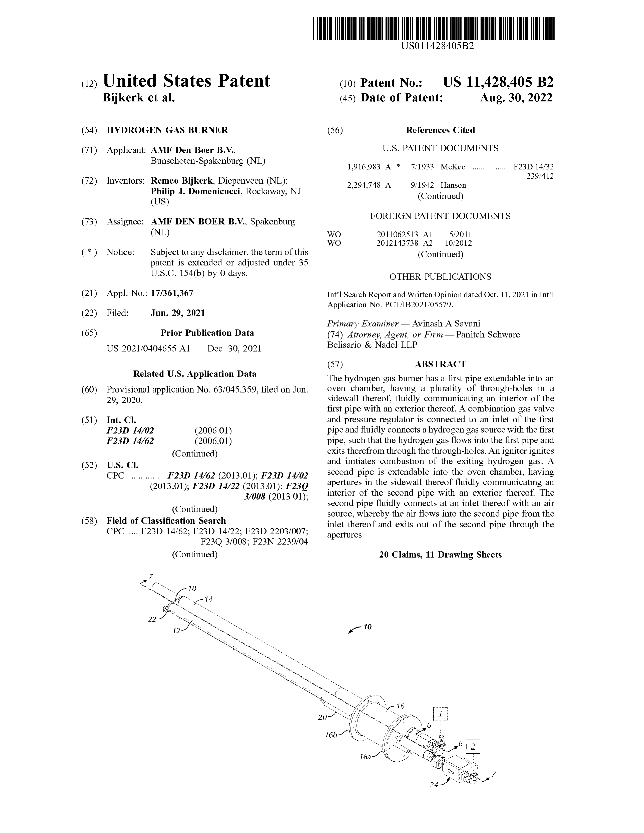
Related U.S. Application Data The hydrogen gas burner has aa first pipe extendable into an ( 60 ) Provisional application No. 63 / 045,359, filed on Jun . oven chamber, having a plurality of through -holes in a 29 , 2020 . sidewall thereof, fluidly communicating an interior of the first pipe with an exterior thereof. A combination gas valve (51 ) Int. Ci. and pressure regulator is connected to an inlet of the first F23D 14/02 ( 2006.01 ) pipe and fluidly connects a hydrogen gas source with the first F231 14/62 ( 2006.01 ) pipe , such that the hydrogen gas flows into the first pipe and ( Continued ) exits therefrom through the through -holes . An igniter ignites ( 52) U.S. CI . and initiates combustion of the exiting hydrogen gas. A CPC F23D 14/62 (2013.01 ) ; F23D 14/02 second pipe is extendable into the oven chamber, having (2013.01 ) ; F23D 14/22 ( 2013.01 ) ; F23Q apertures in the sidewall thereof fluidly communicating an 3/008 (2013.01 ) ; interior of the second pipe with an exterior thereof. The ( Continued ) second pipe fluidly connects at an inlet thereof with an air ( 58 ) Field of Classification Search source , whereby the air flows into the second pipe from the
inlet thereof and exits out of the second pipe through the apertures.
( Continued ) 20 Claims , 11 Drawing Sheets
Page 2
( 51 ) Int . Ci. 7,677,884 B2 3/2010 Kaupert et al. F23D 14/22 ( 2006.01 ) 8,669,499 B2 3/2014 Conrad F230 3/00 ( 2006.01 ) 8,734,632 B1 5/2014 Eisman ( 52) U.S. Ci. 8,840,942 B2 9/2014 Olver et al .
CPC F23D 2203/007 ( 2013.01 ) ; F23N 2239/04 10,066,838 B2 9/2018 Deng
( 58 ) Field of Classification Search 10,627,107 B2 4/2020 Hirata et al . USPC 431/264 , 52 10,648,662 B2 5/2020 Maitani et al. See application file for complete search history. 2003/0213484 Al 11/2003 Alden et al .
( 56 ) References Cited 2010/0024799 A1 2/2010 Conrad
1/1950 Houlis 2018/0119954 Al 5/2018 Fu 2,494,243 A 2018/0224122 A1 8/2018 Mimura
3,172,460 A 3/1965 Temple 2019/0072273 A1 3/2019 Hirata et al .
4,465,455 A 8/1984 Meyer FOREIGN PATENT DOCUMENTS
5,435,343 A 7/1995 Buezis WO 2017136489 A1 8/2017 5,735,503 A 4/1998 Hietkamp WO 2019032068 A2 2/2019
6,302,143 B1 10/2001 Sarlak * cited by examiner
Page 3
Drawing sheet — no readable text.
Page 4
Drawing sheet — no readable text.
Page 5
Drawing sheet — no readable text.
Page 6
Drawing sheet — no readable text.
Page 7
Drawing sheet — no readable text.
Page 8
Drawing sheet — no readable text.
Page 9
Drawing sheet — no readable text.
Page 10
Drawing sheet — no readable text.
Page 11
Drawing sheet — no readable text.
Page 12
Drawing sheet — no readable text.
Page 13
Drawing sheet — no readable text.
Page 14
HYDROGEN GAS BURNER In any of the previous configurations, the apertures may be coplanar with the plurality of through -holes.
CROSS - REFERENCE TO RELATED In any of the previous configurations, the apertures may APPLICATION span a length substantially equal to the portion of the length 5 of the first pipe having the plurality of through -holes.
This application claims priority from U.S. Provisional include Inany of the previous configurations, the second pipe may Patent Application No. 63 / 045,359 , titled “ Hydrogen Gas sidewall athereof ribbon along the portion of the length of the , the ribbon defining the apertures.
Burner ” , filed on Jun. 29 , 2020 , the entire contents of which In any of the previous configurations, at least one of the are incorporated by reference herein . 10 first pipe and the second pipe may be substantially cylin BACKGROUND OF THE DISCLOSURE drical.
In any of the previous configurations, the plurality of through - holes may be arranged in at least one row along the
The disclosure relates to a hydrogen gas burner for direct, portion indirect or hybrid fired ovens . of the length of the first pipe .
Conventional direct fired pipe ribbon burners for an oven , through -holesof the previous configurations, the plurality of may be arranged in a single row along the e.g. , a commercial/industrial oven, generally operate on the portion of the length of the first pipe . combustion of natural gas . Byproducts of natural gas com In any of the previous configurations, the first pipe may be bustion do not contaminate the food products. One draw configured to project between approximately 19.6 inches back of the combustion of natural gas to generate heat, 20 and approximately 240 inches into the oven chamber. however, is the accompanying emissions, such as , for In any of the previous configurations, at least one of the example, carbon emissions in the form of carbon monoxide first pipe and the second pipe may define an internal diam and carbon dioxide, as well as other gases. Moreover, eter of between approximately 0.75 inch IPS and approxi supplying burners with natural gas involves obtaining , trans- mately 2.0 inches IPS .
porting, sourcing, and refining steps that require energy, 25 In any of the previous configurations, each pair of suc which also results in emissions , such as carbon emissions . cessive through -holes of the plurality of through -holes may It would , therefore, be advantageous to manufacture a be spaced between approximately 0.12 inch and approxi burner for an oven or grill that utilizes a greener source of mately 0.35 inch apart, on - center.
energy without sacrificing the quality of the food product, In any of the previous configurations, each one of the e.g. , a fuel other than natural gas for combustion , such as 30 plurality of through -holes may define an internal diameter hydrogen gas , which results in reduced emissions, e.g. , between approximately 0.008 inch and approximately 0.03 reduced carbon footprint, upon combustion . Byproducts of inch .
hydrogen combustion also do not contaminate food prod- In any of the previous configurations, the burner may be ucts . configured to produce between approximately 450 Btu / in 35 and approximately 2,000 Btu / in of heat.
BRIEF SUMMARY OF THE DISCLOSURE In any of the previous configurations, the predetermined pressure regulated by the combination gas valve and pres
Briefly stated , one aspect of the present disclosure is sure regulator may be between approximately 2" wc and directed to a hydrogen gas burner. The burner has a first pipe approximately 24 " wc .
extendable into an oven chamber, the first pipe including a 40 In any of the previous configurations, the second pipe may plurality of through -holes in aa sidewall thereof and along a be configured to release between approximately 83.6 ft /hr portion of a length thereof, fluidly communicating an inte- and approximately 1,484 ft /hr of air into the oven chamber. rior of the first pipe with an exterior thereof. A combination Another aspect of the present disclosure is directed to a gas valve and pressure regulator is connected to an inlet of gas burner. The burner includes a first pipe extendable into the first pipe , the combination gas valve and pressure 45 an oven chamber, the first pipe including a plurality of regulator being configured to fluidly connect a source of through - holes in a sidewall thereof and along a portion of a hydrogen gas with the interior of the first pipe at a prede- length thereof, fluidly communicating an interior of the first termined pressure , such that the hydrogen gas flows into the pipe with an exterior thereof. A combination gas valve and first pipe from the inlet thereof and exits out of the first pipe pressure regulator is connected to an inlet of the first pipe , through the plurality of through -holes. An igniter is config- 50 the combination gas valve and pressure regulator being ured to provide an electrical spark adjacent at least one of the configured to selectively, fluidly connect a source of hydro plurality of through -holes, and, in turn , ignite and initiate gen gas with the interior of the first pipe at a predetermined combustion of the hydrogen gas exiting from the plurality of pressure to selectively permit the hydrogen gas to flow into through -holes. A second pipe is extendable into the oven the first pipe from the inlet thereof and exit out of the first chamber, the second pipe having a plurality of apertures 55 pipe through the plurality of through -holes. A first igniter is along a portion of a length of a sidewall thereof and fluidly configured to selectively provide an electrical spark adjacent communicating an interior of the second pipe with an at least one of the plurality of through -holes, and, in turn , exterior thereof. The second pipe is configured to fluidly selectively ignite and initiate combustion of the hydrogen connect at an inlet thereof with a source of air, such that the gas exiting from the plurality of through -holes. A second air flows into the second pipe from the inlet thereof and exits 60 pipe is extendable into the oven chamber, the second pipe out of the second pipe through the apertures. having a ribbon extending along a portion of a length thereof In one configuration, the first pipe and the second pipe and fluidly communicating an interior of the second pipe may be coplanar and extend parallel to one another. with an exterior thereof. A mixing valve is connected to an In any of the previous configurations, the second pipe may inlet of the second pipe , the mixing valve being configured be positioned on an opposite side of the first pipe from the 65 to receive air from a source of air, selectively receive aa fuel plurality of through -holes, and the apertures face toward the gas from a source of the fuel gas , selectively mix the air and first pipe . the fuel gas together and selectively, fluidly connect the
Page 15
mixed air and fuel gas with the interior of the second pipe In any of the previous configurations, the plurality of such that the mixed air and fuel gas flows into the second through -holes may be arranged in at least one row along the pipe from the inlet thereof and exits out of the second pipe portion of the length of the first pipe . through the ribbon . A second igniter is configured to selec- In any of the previous configurations, the second pipe may tively provide an electrical spark adjacent the ribbon , and , in 5 be positioned on an opposite side of the first pipe from the turn , selectively ignite and initiate combustion of the mixed plurality of through -holes.
air and fuel gas exiting from the ribbon . In any of the previous configurations, the ribbon may be In one configuration, the second pipe may be positioned substantially equal in length to the portion of the length of on an opposite side of the first pipe from the plurality of the first pipe having the plurality of through -holes . through -holes, and the ribbon extends outwardly in aa direc- 10 In any of the previous configurations, the burner may tion away from the first pipe . further include a combination gas valve and zero- pressure In any of the previous configurations, the gas burner may regulator in fluid communication with an inlet of the mixing valve , the combination gas valve and zero - pressure regulator further include a combination gas valve and zero - pressure being configured to prohibit flow of the fuel gas from the regulator in fluid communication with an inlet of the mixing 15 source valve , the combination gas valve and zero - pressure regulator of the second ofthe fuel gas to the mixing valve in the first position configured to selectively permit or prohibit flow of the fuel fuel gas from the pipe and configured to permit the flow of the gas from the source of the fuel gas to the mixing valve . source of the fuel gas to the mixing valve In any of the previous configurations, the fuel gas may in the second position of the second pipe . In any of the previous configurations, the fuel gas may take the form of natural gas , a mixed blend of natural gas and 20 take the form of natural gas , a mixed blend of natural gas and hydrogen gas , propane or a mixed blend of propane and hydrogen gas , propane or a mixed blend of propane and hydrogen gas . hydrogen gas .
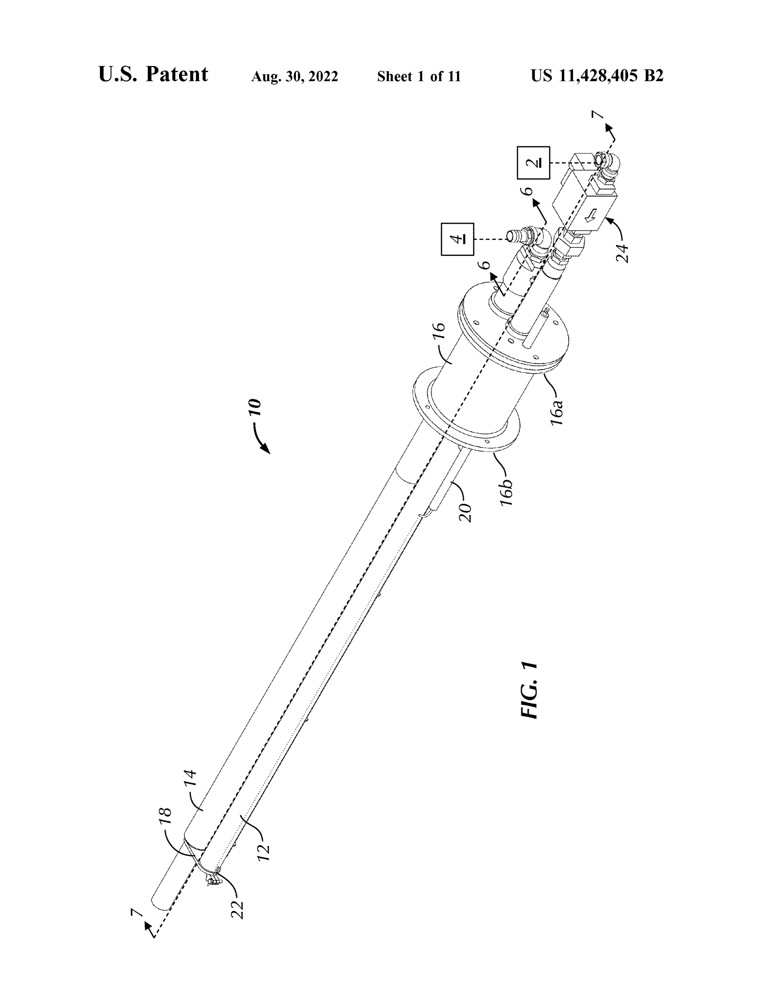
Another aspect of the present disclosure is directed to a gas burner. The burner includes a first pipe extendable into BRIEF DESCRIPTION OF THE SEVERAL an oven chamber, the first pipe including a plurality of 25 VIEWS OF THE DRAWINGS through -holes in a sidewall thereof and along a portion of a length thereof, fluidly communicating an interior of the first The following description of embodiments of the disclo pipe with an exterior thereof. A combination gas valve and sure will be better understood when read in conjunction with pressure regulator is connected to an inlet of the first pipe , the appended drawings. It should be understood, however, the combination gas valve and pressure regulator being 30 that the disclosure is not limited to the precise arrangements configured to selectively, fluidly connect a source of hydro- and instrumentalities shown . In the drawings : gen gas with the interior of the first pipe at a predetermined FIG . 1 is a top , front and proximal perspective view of a pressure to selectively permit the hydrogen gas to flow into hydrogen gas burner for use with a direct, indirect or hybrid the first pipe from the inlet thereof and exit out of the first fired oven , according to a first embodiment of the present pipe through the plurality of through -holes. A first igniter is 35 disclosure ;
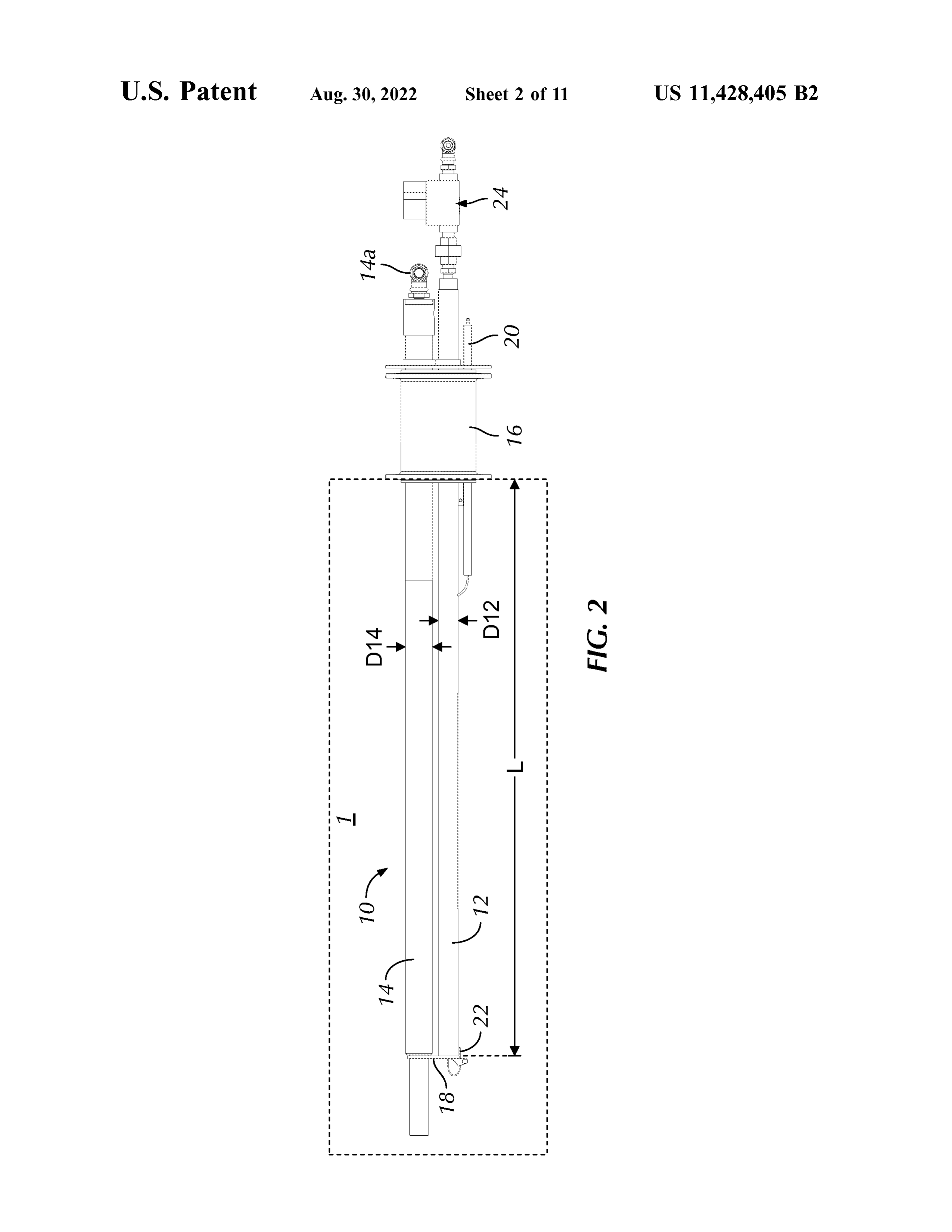
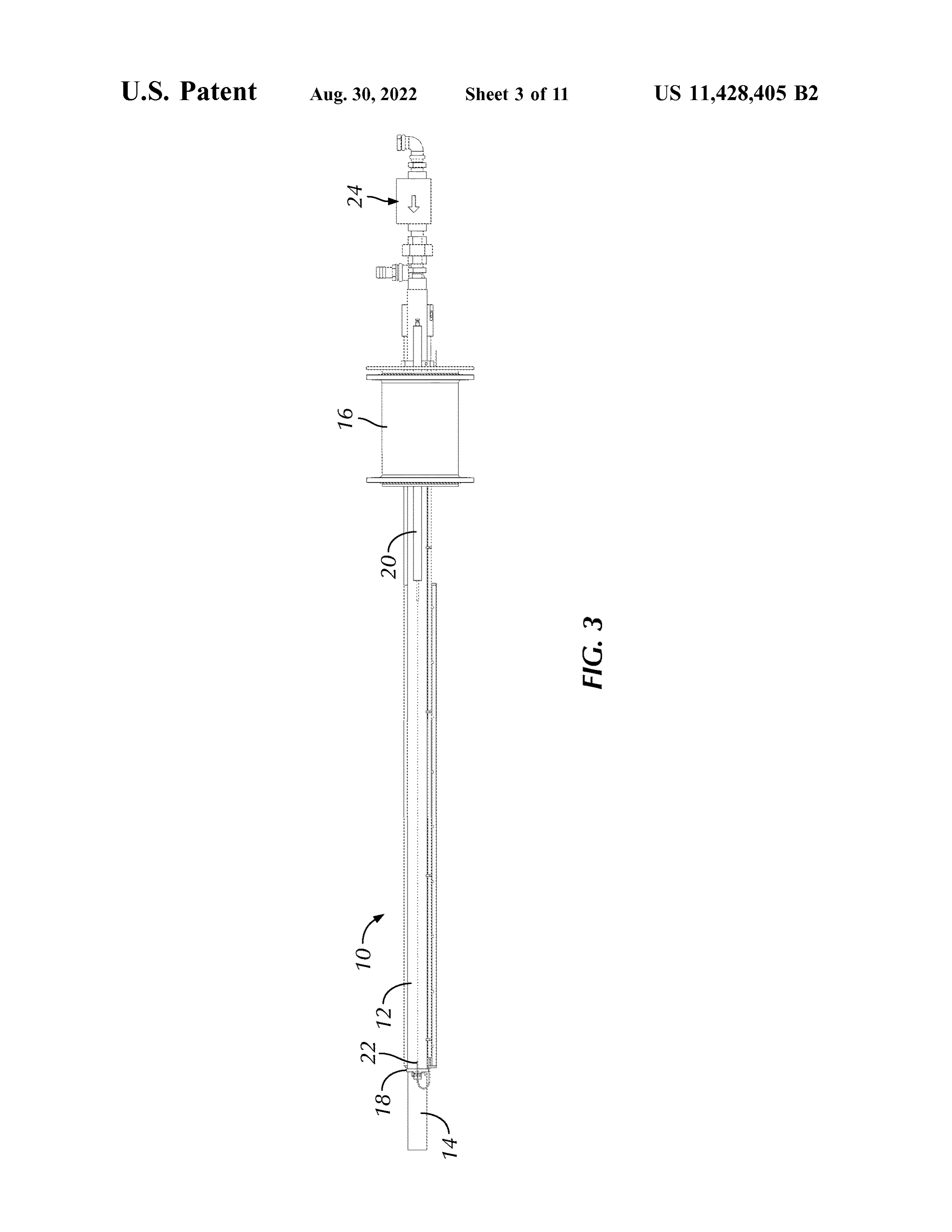
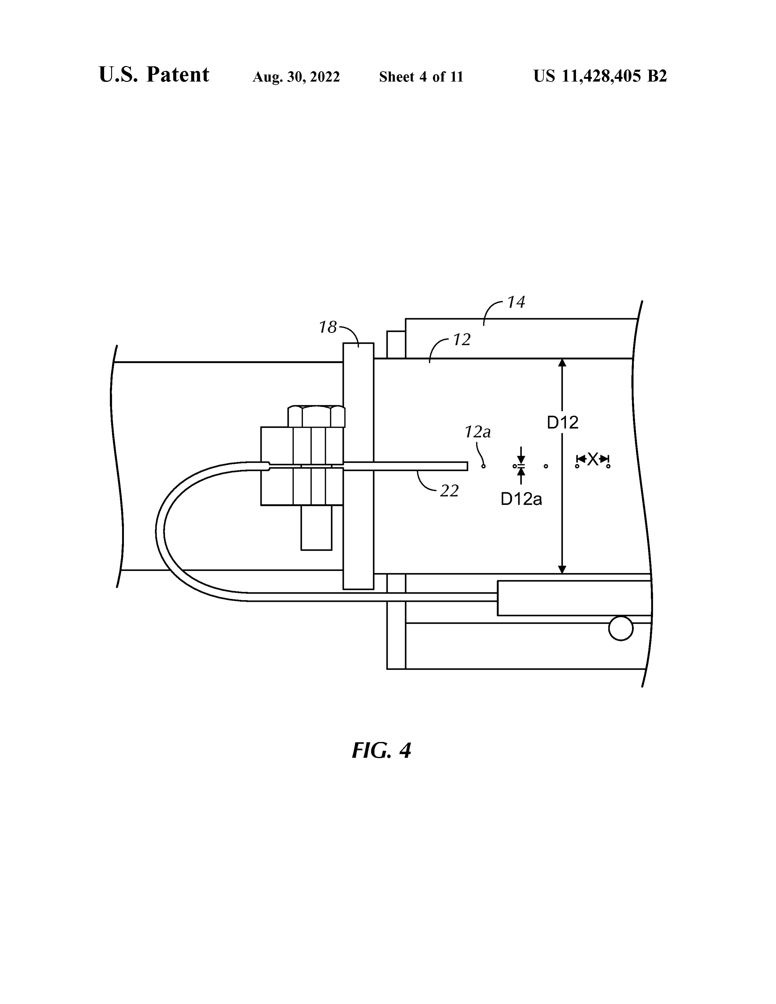
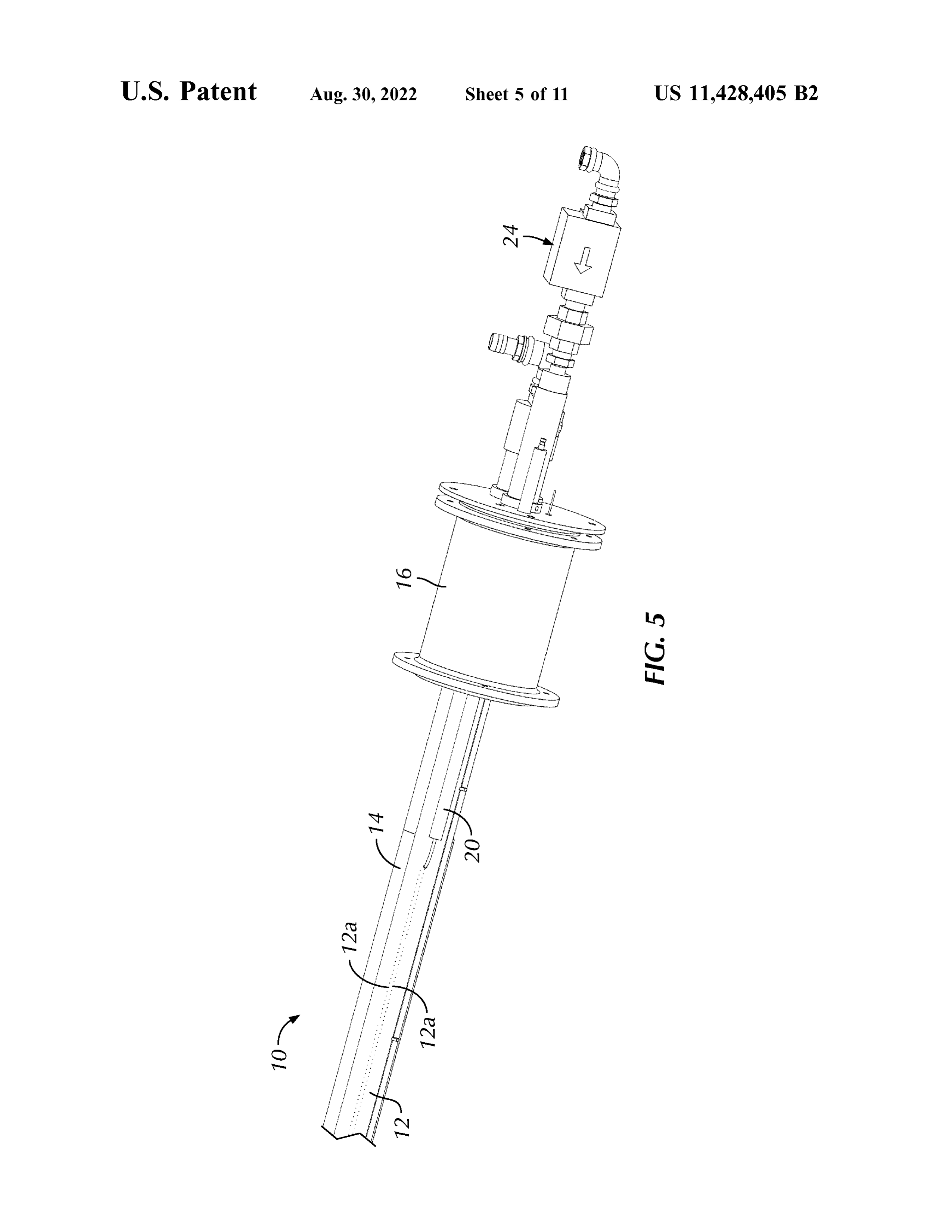
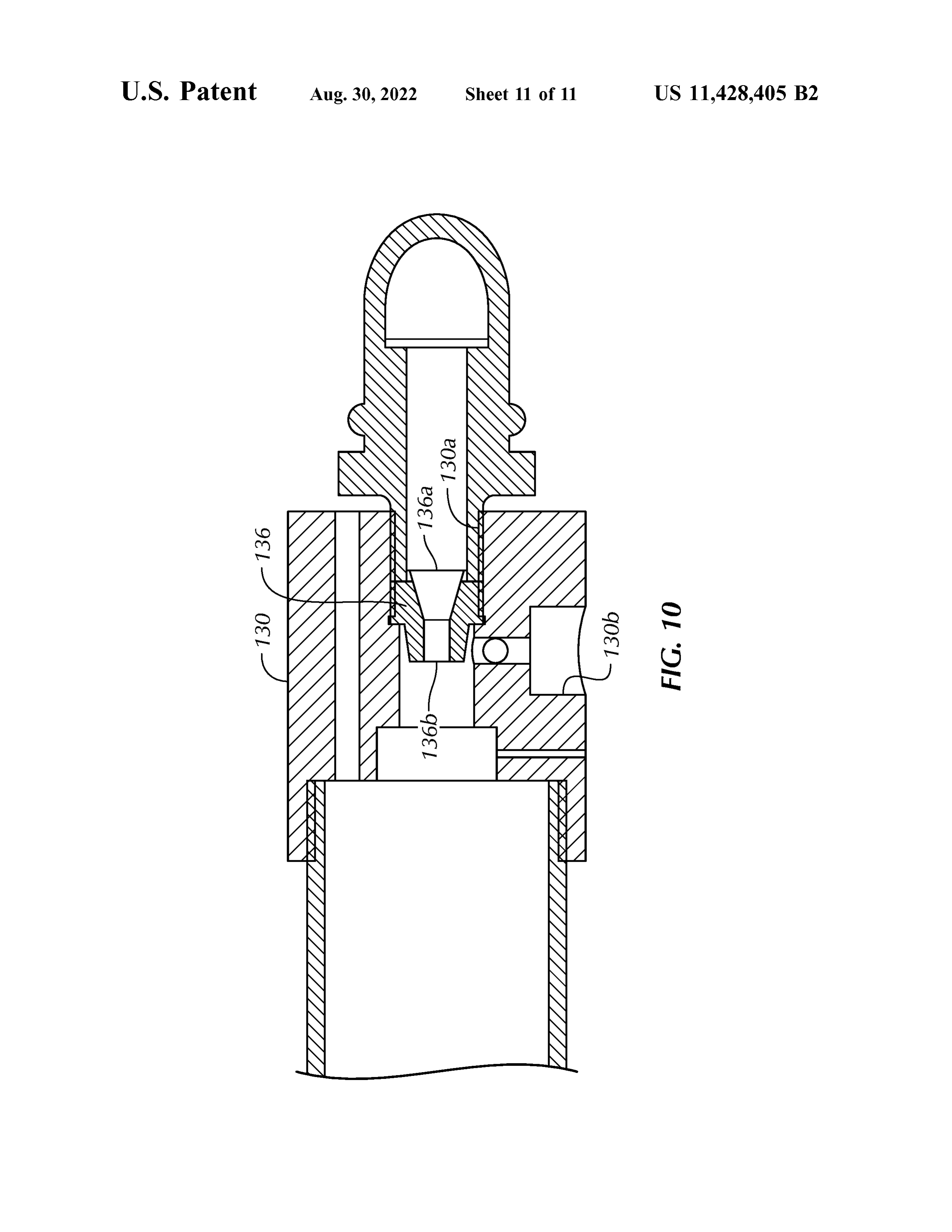
configured to selectively provide an electrical spark adjacent FIG . 2 is a top plan view of the burner of FIG . 1 ; at least one of the plurality of through -holes, and, in turn , FIG . 3 is a front elevational view of the burner of FIG . 1 ; selectively ignite and initiate combustion of the hydrogen FIG . 4 is an enlarged, partial front elevational schematic gas exiting from the plurality of through -holes. A second view of aa distal end of a first pipe of the burner of FIG . 1 ; pipe is extendable into the oven chamber, the second pipe 40 FIG . 5 is a partial perspective view of an alternative having a ribbon extending outwardly therefrom along a configuration of the burner of FIG . 1 , employing two rows portion of a length thereof and fluidly communicating an of apertures along the first pipe ;
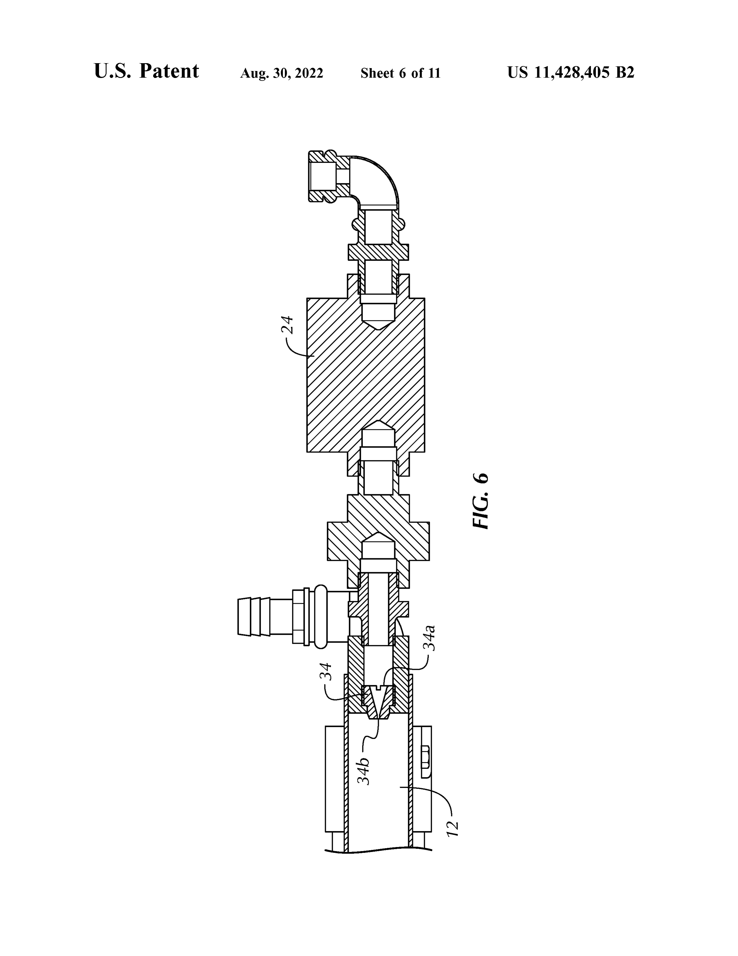
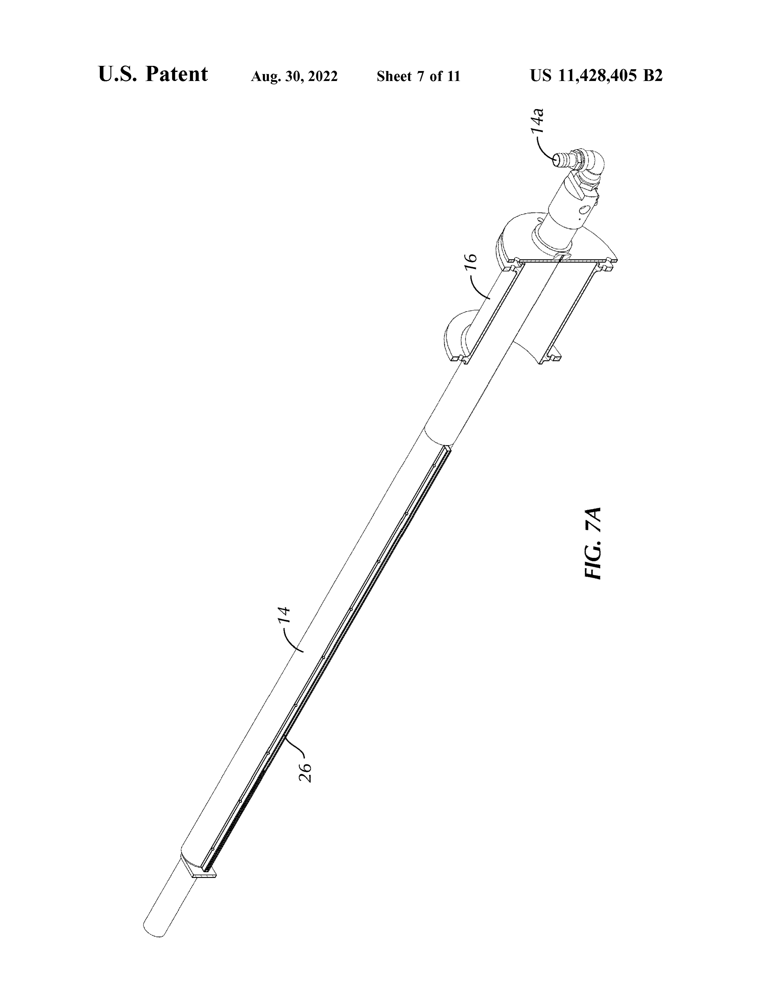
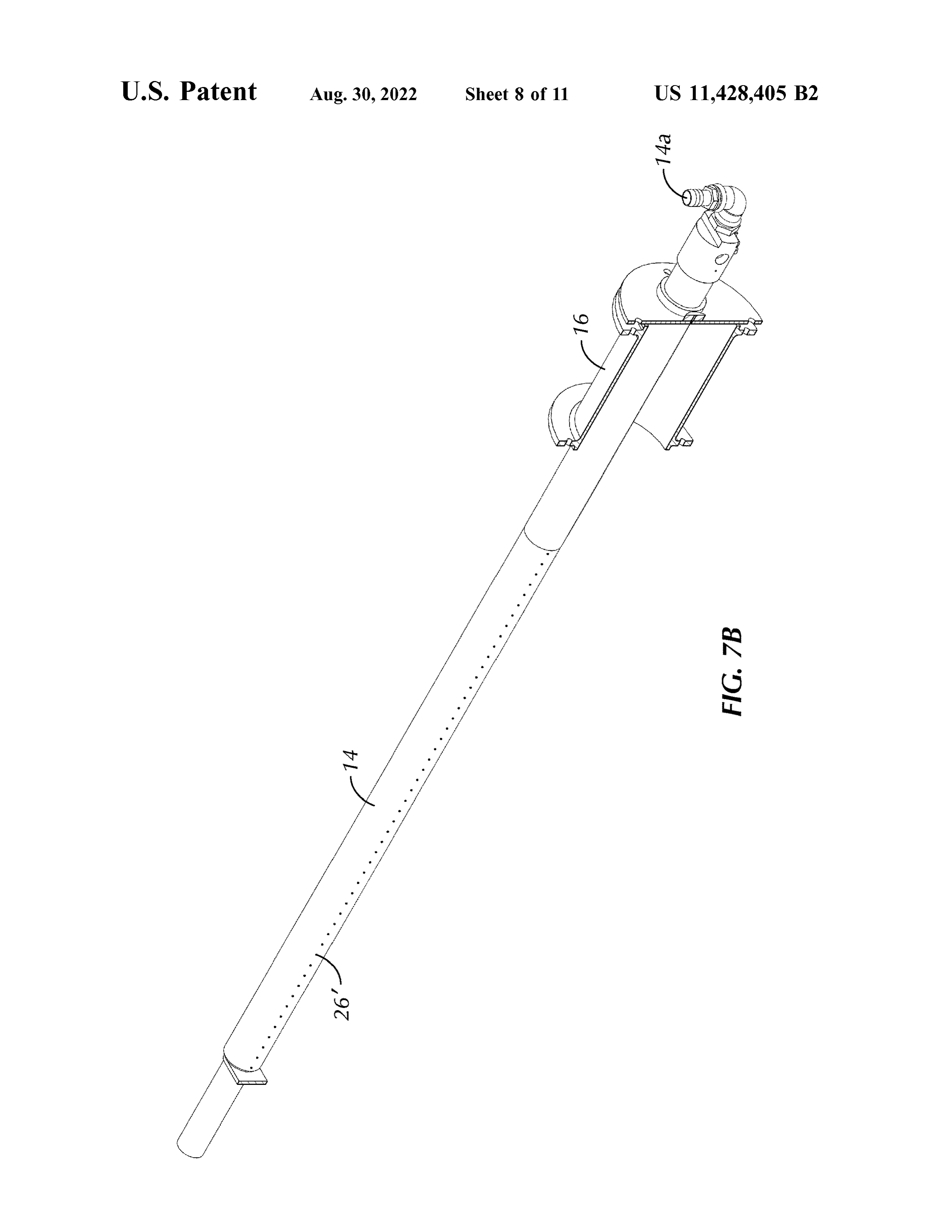
interior of the second pipe with an exterior thereof, the FIG . 6 is a partial, cross - sectional elevational view of the second pipe being rotatable about a central axis thereof burner of FIG . 1 , taken along sectional line 6-6 of FIG . 1 ; between a first position and a second position . In the first 45 FIG . 7A is a cross - sectional perspective view of the position , the ribbon extends outwardly toward the first pipe , burner of FIG . 1 , taken along sectional line 7-7 of FIG . 1 ; and in the second position , the ribbon extends outwardly in FIG . 7B is a cross - sectional perspective view of an a direction away from the first pipe . A mixing valve is alternative configuration of the burner of FIG . 1 , taken along connected to an inlet of the second pipe , the mixing valve sectional line 7-7 of FIG . 1 ;
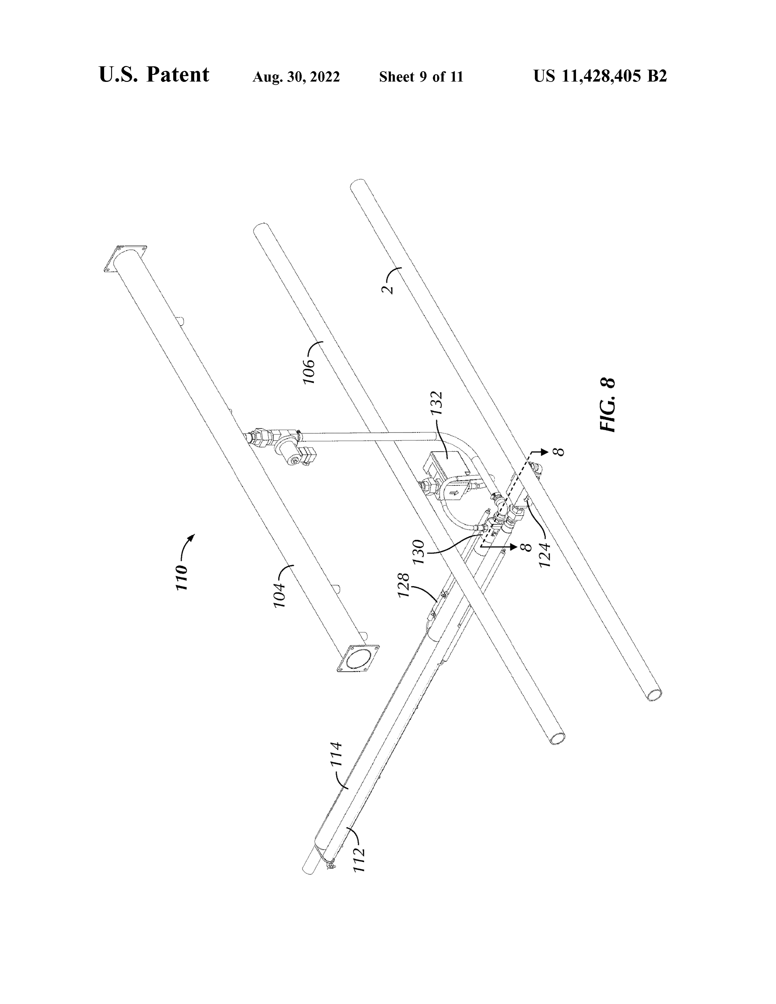
being configured to receive air from a source of air in the 50 FIG . 8 is a top , front and proximal perspective view of a first position of the second pipe and fluidly connect the air gas burner assembly for use with a direct , indirect or hybrid with the interior of the second pipe , such that the air flows fired oven , according to a second embodiment of the present into the second pipe from the inlet thereof and exits out of disclosure;
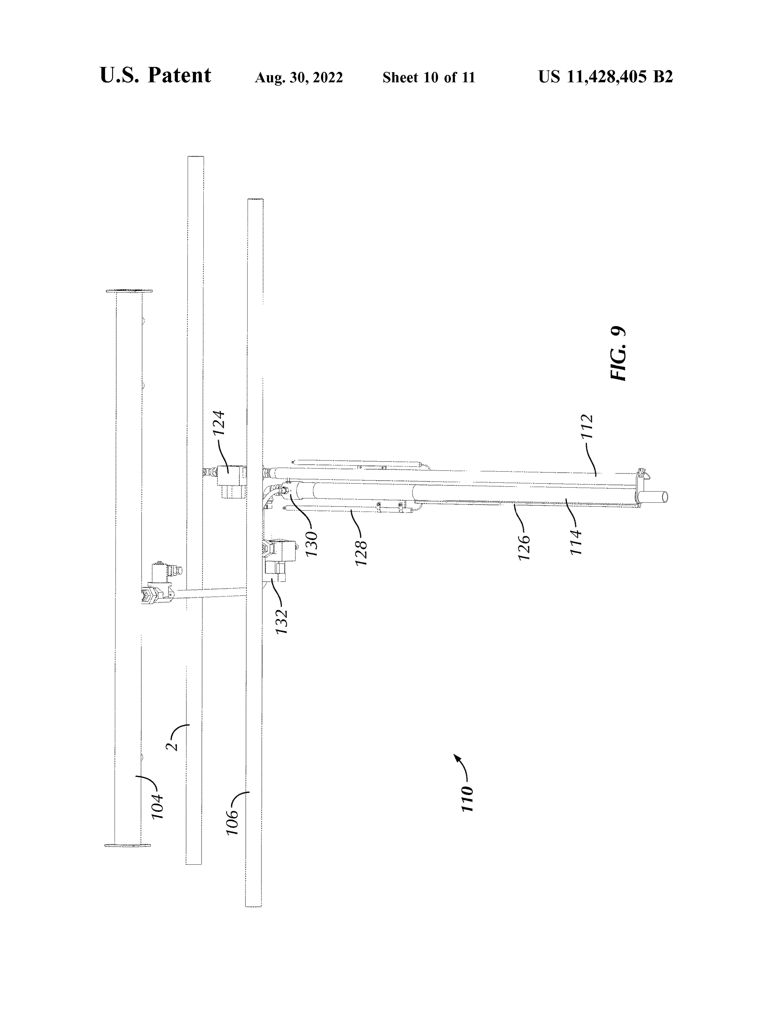
the second pipe through the ribbon . The mixing valve is also FIG . 9 is a top and distal perspective view of the burner configured to receive air from the source of air and receive 55 assembly of FIG . 8 ; and a fuel gas from a source of the fuel gas in the second position FIG . 10 is a partial, cross - sectional plan view of the of the second pipe , mix the air and the fuel gas together and burner of FIG . 8 , taken along sectional line 8-8 of FIG . 8 . direct the mixed air and fuel gas into the interior of the second pipe such that the mixed air and fuel gas flows into DETAILED DESCRIPTION OF THE the second pipe from the inlet thereof and exits out of the 60 DISCLOSURE second pipe through the ribbon . A second igniter is config ured to provide an electrical spark adjacent the ribbon in the Certain terminology is used in the following description second position of the second pipe , and, in turn , selectively for convenience only and is not limiting . The words “ lower , " ignite and initiate combustion of the mixed air and fuel gas “ bottom , " " upper” and “ top ” designate directions in the exiting from the ribbon . 65 drawings to which reference is made . The words “ inwardly , " In one configuration , the first pipe and the second pipe outwardly , " " upwardly ” and “ downwardly ” refer to direc may be coplanar and extend parallel to one another . tions toward and away from , respectively, the geometric
Page 16
center of the burner, and designated parts thereof, in accor- those of ordinary skill in the art, the mounting spool pipe 16 dance with the present disclosure. Unless specifically set extends through, and is secured to , the oven chamber wall forth herein , the terms “ a ,” “ an ” and “ the ” are not limited to ( not shown) in a manner well understood by those of one element, but instead should be read as meaning “ at least ordinary skill in the art. That is , the length of the mounting
one . ” The terminology includes the words noted above, 5 spool pipe 16 generally corresponds to the thickness of the derivatives thereof and words of similar import. oven chamber wall and the flanged ends 16a , 16b of the It should also be understood that the terms “ about," mounting spool pipe 16 are secured, e.g. , fastened , to “ approximately,” “ generally , ” “ substantially ” and like terms, opposing sides of the wall .
used herein when referring to a dimension or characteristic In one embodiment, and as shown in FIG . 2 , the first pipe of a component of the disclosure, indicate that the described 10 12 may define an operative length L , i.e. , the length of the dimension /characteristic is not a strict boundary or param- portion of the first pipe 12 extending into the oven chamber eter and does not exclude minor variations therefrom that are 1 , between approximately 500 mm ( 19.6 inches) and functionally similar. At a minimum , such references that approximately 6,100 mm (240 inches ), but the disclosure is include aa numerical parameter would include variations that, not so limited . In one embodiment, the first pipe 12 defines using mathematical and industrial principles accepted in the 15 an internal diameter D12 of between approximately 20 mm art ( e.g. , rounding , measurement or other systematic errors , (0.75 inch IPS , i.e. , iron pipe size indicating inside diameter) manufacturing tolerances, etc. ) , would not vary the least and approximately 50 mm (2 inches IPS ) . The first pipe 12 significant digit . includes a plurality of apertures /through -holes 12a in the Referring to the drawings in detail, wherein like numerals sidewall of the first pipe 12 , e.g. , laser or EDM cut , drilled indicate like elements throughout, there is shown in FIGS . 20 or the like ( shown best in FIGS . 3 , 4 ) , positioned in series 1-7B a burner 10 for use with a direct, indirect or hybrid along a portion of the length L thereof, defining the flame fired oven, e.g. , a commercial /industrial oven or grill, in space of the first pipe 12 .
accordance with a first embodiment of the present disclo- In one configuration , the plurality of apertures 12a are sure. The burner 10 includes aa first pipe 12 and aa second pipe arranged in at least one row of apertures 12a positioned 14. In one configuration, the first and second pipes 12 , 14 are 25 along a portion of the length L of the first pipe 12. For substantially cylindrical along the length thereof, i.e. , define example , as shown best in FIGS . 3 and 4 , the apertures 12a a generally circular cross - section in a plane perpendicular to may be arranged in a single row of apertures 12a . Alterna the length thereof, but the disclosure is not so limited . tively, the more than one row of apertures 12a may be Alternatively, one or both of the first and second pipes 12 , employed for increased thermal output of the burner 10 , 14 may define a non - circular cross - section , such as , for 30 such as , for example, two rows ( see FIG . 5 ) . In one con example, without limitation, a square, oval , indented, dough figuration, the respective rows may be angularly spaced folded or square flattened cross -section , a combination from one another by between approximately 12 ° and thereof along different portions of the length of the pipe ( s ) approximately 15 ° , such as , for example , by approximately or the like . As also should be understood, the first and second 14 ° . In one configuration, the apertures 12a forming one row pipes 12 , 14 may be differently shaped in cross - section from 35 may be axially offset, i.e. , along the length of the first pipe one another. Optionally, one or more of the first and second 12 , from the apertures 12a forming another row . For
pipes 12 , 14 may be at least partially coated with a high example, the apertures 12a of one row may each be posi emissivity thermal protective layer, e.g. , a nano - emissive tioned between two successive apertures 12a of the adjacent coating , such as , for example, as disclosed in U.S. Pat. No. row ( s ).
8,840,942 , the entire contents of which are incorporated by 40 Referring now to FIG . 4 , in one embodiment, each pair of reference herein . successive apertures 12a along a row is spaced a distance X In the illustrated embodiment the first and second pipes between approximately 3 mm ( 0.12 inch ) and approximately 12 , 14 extend generally parallel with one another and are 9 mm (0.35 inch ) apart on - center, such as , for example, positioned along the same plane, but the disclosure is not so without limitation, approximately 5 mm (0.2 inch ) apart, but limited . In the illustrated embodiment, the first and second 45 the disclosure is not so limited . In one embodiment, each pipes 12 , 14 are of differing lengths, but the disclosure is not aperture 12a defines an internal diameter D12a between so limited . The first and second pipes 12 , 14 are secured approximately 0.02 mm ( 0.008 inch ) and approximately relative to one another and relative to an oven chamber 1 0.76 mm ( 0.03 inch ), such as , for example, without limita ( shown schematically in FIG . 2 ) of a direct, indirect or tion , approximately 0.4 mm ( 0.016 inch ), but the disclosure hybrid fired oven (not shown) via a mounting spool pipe 16 50 is not so limited . The plurality of apertures 12a are posi proximate a proximal end of the pipes 12 and 14. The tioned along a horizontal plane extending through both the mounting spool pipe 16 is generally hollow for the first and first and second pipes 12 , 14 , on a side of the first pipe 12 second pipes 12 , 14 to extend therethrough. In one configu- facing away from the second pipe 14. As should be under ration , mounting plates (not shown) may attach to opposing stood by those of ordinary skill in the art, the operative ends of the mounting spool pipe 16 and include respective 55 length L of the first pipe 12 , the internal diameter D12 of the apertures (not shown ) for each of the first and second pipes first pipe , the spacing X between the apertures 12a , the 12 , 14 to extend therethrough , but the disclosure is not so internal diameter D12a of the apertures 12a , and the size of limited . Each aperture may be generally complementary in the oven chamber 1 , or a combination thereof, determines dimension to an outer diameter of the corresponding pipe 12 , the thermal output of the burner 10. In one configuration, the 14 , for securement. The first and second pipes 12 , 14 may 60 burner 10 is configured to produce between approximately also include at least one bracket 18 positioned distally of the 5.14 kW / m (450 Btu/in) and approximately 22.8 kW / m mounting spool pipe 16 and may also be attached to the first (2,000 Btu / in ) of heat .
and second pipes 12 , 14 to secure their relative positioning. As shown best in FIGS . 1-3 and 5 , the burner 10 further As should be understood, however, the first and second pipes includes an igniter 20 ( controlled via a direct spark ignition 12 , 14 may be secured relative to one another and to the 65 ( not shown) ) connected to , or mounted adjacent to , the first mounting spool pipe 16 via other methods currently known pipe 12 in a manner well understood by those of ordinary or that later become known. As should be understood by skill in the art and configured to provide an electrical spark
Page 17
adjacent one or more of the apertures 12a along the first pipe 20 is then actuated to provide the electrical spark which 12. As shown, the igniter 20 extends substantially parallel to ignites the flame along the apertures 12a and initiates the first pipe 12 and is positioned proximate a proximal end combustion of the hydrogen gas exiting from the apertures of the first pipe 12. In the illustrated configuration ( see FIG . 12a . As should be understood the hydrogen gas combusting, 3 ) , the igniter 20 is positioned in the same plane as the 5 i.e. , burning, in the air within the oven chamber 1 of the oven
apertures 12a , but the disclosure is not so limited . Similarly reacts with the oxygen with the air to form moisture, i.e. , to the first and second pipes 12 , 14 , the igniter 20 may extend water vapor, and thermal energy.
through the mounting spool pipe 16 and may be secured by Advantageously, hydrogen gas combustion byproducts the mounting plates, but the disclosure is not so limited . As are free of carbon , and, therefore , carbon emissions are should be understood by those of ordinary skill in the art, the 10 significantly minimized . Additionally, water vapor byprod igniter 20 may take the form of a conventional combination uct of hydrogen gas combustion far exceeds that of natural igniter and flame detection sensor. Optionally, a conven- gas combustion . The relative increase in moisture content tional opposite side sensor 22 may be attached to a distal end within the oven chamber 1 , in aa controlled manner, may aid of the first pipe 12 , e.g. , to the bracket 18 , and electrically in a baking process , such as , for example, with baking of connected to the direct spark ignition of the burner 10 in a 15 grain - based products, e.g. , bread , bagels , pretzels and the manner well understood by those of ordinary skill in the art. like . For example, the increase of moisture content may aid As also shown in FIGS . 1-3 , 5 and 6 , a combination gas in more efficient heat transfer to the grain -based product,
valve ( double valved) and pressure regulator 24 , e.g. , with- thereby reducing baking time . The increase in moisture out limitation, a Honeywell model number VK4105M5215 content also enables heat to reach the inside of the product U gas control with a gas regulator, is connected to an inlet , 20 sooner , advancing functions such as yeast kill , gelatiniza e.g. , at a proximal end , of the first pipe 12. As should be tion , and arrival time , i.e. , dough becomes bread sooner . The understood by those of ordinary skill in the art, the combi- moisture may subsequently be extracted in a manner well nation gas valve and pressure regulator 24 selectively fluidly understood by those of ordinary skill in the art) at a specific connects a source of combustion fuel / gas 2 ( shown sche- point in the baking process to allow for other objectives, matically in FIG . 1 ) flowing from a main gas manifold ( not 25 such as product color and crust, to develop. Accordingly , the shown ) with the inlet of the first pipe 12. In the present burner 10 advantageously utilizes a greener source of energy disclosure, the combustion fuel/ gas utilized with the first while also producing at least the same or better -quality pipe 12 is hydrogen gas . In one configuration, the combi- products.
nation gas valve and pressure regulator 24 is configured to Turning to the second pipe 14 , and referring to FIGS . 2 , regulate the hydrogen gas flowing into the first pipe 12 to a 30 7A and 7B , the second pipe 14 defines an internal diameter pressure between approximately 5 mbar ( 2 " wc , i.e. , inches D14 of between approximately 20 mm (0.75 inch IPS ) and of water column) and approximately 60 mbar ( 24 " wc ) . approximately 50 mm ( 2 inch IPS ) . As shown best in FIG . In one configuration, as shown in FIG . 6 , a combustion 7A , the second pipe 14 may take the form of a ribbon burner, gas - flow nozzle 34 , is fluidly interposed between the com- having a ribbon 26 laterally extending from , or embedded in bination gas valve and pressure regulator 24 and the first 35 a side wall of, the second pipe 14 along a portion of the pipe 12 to set the maximum amount of combustion gas length of the second pipe 14 in a manner well understood by entering the first pipe 12. In the illustrated embodiment, the those of ordinary skill in the art. As should be understood by nozzle 34 is sealingly positioned within a proximal end of those of ordinary skill in the art, the ribbon 26 includes a the first pipe 12. As shown , the nozzle 34 defines an inlet plurality of ported and / or meshed and stacked, laterally opening 34a and an outlet opening 34b ( according to the 40 oriented ribbon strips (not shown ), e.g. , constructed of steel , direction of flow into the first pipe 12 ) . In the illustrated therein (not shown) , forming a lattice of apertures / channels embodiment, the inner diameter of the combustion gas - flow therebetween . The strips generally extend the length of the nozzle 34 generally tapers from aa wider inlet opening 34a to ribbon 26. As also should be understood by those of ordinary a narrower outlet opening 34b . The diameter of the outlet skill in the art, the ribbon 26 may define any internal pattern opening 34b is selected relative to the maximum amount of 45 of the ported and / or meshed and stacked ribbon strips, combustion gas required in the first pipe 12 to achieve the currently known or that later becomes known . Alternatively, intended thermal output of the burner 10. As should be and as shown best in FIG . 7B , the second pipe 14 may understood by those of ordinary skill in the art, the calibrated include a plurality of apertures 26 ' formed in the sidewall of diameter of the outlet opening 34b , in combination with the the second pipe 14 ( replacing or supplementing the ribbon pressure of the combustion gas , determines the flow rate of 50 26 ) , e.g. , laser or EDM cut , drilled or the like , and positioned the combustion gas entering the first pipe 12 , i.e. , according along a portion of the length of the second pipe 14. In one to Bernoulli's equation. In one configuration , the outlet configuration , the length of the ribbon 26 ( or the collective opening 34b of the nozzle 34 may define aa diameter between span of the apertures 26 ' ) may correspond to the flame space approximately 0.019 inch (0.5 mm ) and approximately of the first pipe 12. That is , the length of the ribbon 26 (or 0.275 inch (7 mm ) depending on the maximum flow rate for 55 the collective span of the apertures 26 ') may be substantially the particular length of the first pipe 12 , such as , for equal to the portion of the first pipe 12 having the apertures example , without limitation, approximately 0.07 inch ( 1.8 12a . In one configuration, the ribbon 26 may project in mm ). substantially the same plane as the apertures 12a . In operation, the valves ( not shown ), e.g. , solenoid valves , The second pipe 14 may be connected to an air- only within the combination gas valve and pressure regulator 24 60 source 4 ( shown schematically in FIG . 1 ) via a connection are opened to allow the flow of hydrogen gas from the fitting 14a at an inlet , e.g. , at a proximal end, of the second hydrogen gas source 2 into the first pipe 12 and the pressure pipe 14. For example, the second pipe 14 may release regulator ( not shown) within the combination gas valve and between approximately 2.37 m3/ hr ( 83.6 ft3 / hr) and approxi pressure regulator 24 regulates the pressure of the hydrogen mately 42.04 m3/ hr ( 1,484 ft /hr) of excess air into the oven gas within the first pipe 12. The nozzle 34 sets the maximum 65 chamber 1. The second pipe 14 , releasing only air ( via the flow rate of the hydrogen gas into the first pipe 12. The ribbons 26 or the apertures 26 ' ) , may be employed to assist hydrogen gas then flows out of the apertures 12a . The igniter in reduction of nitrogen oxides. That is , the second pipe 14 ,
Page 18
positioned on an opposite side of the first pipe 12 from the The mixing valve 130 mixes the air and natural gas (or air apertures 12a , may release air to substantially envelope the and natural gas/hydrogen gas blend ) together according to a first pipe 12. Nitrogen oxides are generally produced from predetermined ratio ( of air to natural gas according to the the reaction of nitrogen and oxygen gases in the air during percentage of natural gas present) and fluidly connects the combustion, especially at high temperatures. In operation of 5 mixed air and natural gas (or mixed air and natural gas/ the of the burner 10 , release of air from the second pipe 14 hydrogen gas blend ) with the second pipe 114 in a manner may assist in cooling the flame along the apertures 12a , well understood by those of ordinary skill in the art. A combination valve and zero - pressure regulator 132 , e.g. , thereby reducing nitrogen oxide formation . Release of air without limitation a Honeywell model number from the second pipe 14 may also assist with the hydrogen 10 VK4125V2029 C series combination valve , zero regulator, gas combustion process , e.g. , maintaining an appropriate and ignition system , may be employed in line between the volume of air within the oven chamber 1 .
FIGS . 8-10 illustrate aa second embodiment of a burner for source of natural gas (or natural gas /hydrogen gas blend ) use with a direct , indirect or hybrid fired oven . The reference those of ordinary skill in the130.art,Astheshould 106 and the mixing valve be understood by numerals of the second embodiment are distinguishable 15 e.g. , solenoid valves , within the combination gas( notvalve gas valves shown ), and from those of the above -described first embodiment by a zero -pressure regulator 132 regulate, i.e. , selectively permit factor of one hundred ( 100 ) , but otherwise indicate the same or prohibit , the flow of natural gas ( or natural gas /hydrogen elements as indicated above , except as otherwise specified. gas blend ) from the natural gas (or natural gas /hydrogen gas The burner 110 of the present embodiment is similar to that blend ) source 106 to the mixing valve 130. The zero of the earlier embodiment. Therefore, the description of 20 pressure regulator ( not shown) within the combination gas certain similarities and modes of operation between the valve and zero - pressure regulator 132 selectively allows the embodiments may be omitted herein for the sake of brevity flow of natural gas (or natural gas /hydrogen gas blend) from and convenience, and, therefore, is not limiting . the natural gas ( or natural gas /hydrogen gas blend ) source A primary difference of the burner 110 over the burner 10 106 , through the combination gas valve and zero - pressure is the selective operability of the second pipe 114 as a fuel 25 regulator 132 , and to the gas inlet 130b of the mixing valve gas burner. The fuel gas operating as the energy source for 130 upon generation of a venturi ( see FIG . 10 ) , i.e. , a the second pipe 114 may take the form of, for example, vacuum , created by the flow of air through the mixing valve natural gas , a mixed blend of natural gas and hydrogen gas , 130 via the air inlet 130a .
propane or a mixed blend of propane and hydrogen gas . For In one configuration, as shown in FIG . 10 , the air inlet the sake of brevity, the following description recites the use 30 130a of the mixing valve 130 may include (therein , or of natural gas or a mixed blend of natural gas and hydrogen adjacent thereto , and upstream of or proximate to the gas gas as the fuel gas for the second pipe 114 , but the second inlet 130b ) an airflow nozzle 136 therein , to set the maxi pipe 114 may equally be operable with other fuel gases , such mum amount of air mixing with the natural gas (or natural as , for example, the other fuel gasses previously identified . gas /hydrogen gas blend ) and subsequently entering the As shown best in FIG . 9 , the second pipe 114 is oriented 35 second pipe 114. As shown, the nozzle 136 defines an inlet such that the ribbon 126 faces away from the first pipe 112 . opening 136a and an outlet opening 136b ( according to the That is , second pipe 114 is rotated substantially 180 ° from direction of flow into the second pipe 114 ) . In the illustrated the second pipe 14 of FIGS . 1-7B . The burner assembly 110 embodiment, the inner diameter of the airflow nozzle 136 includes a second igniter 128 ( controlled via aa direct spark generally tapers from a wider inlet opening 136a to a ignition ( not shown)) connected to , or positioned adjacent, 40 narrower outlet opening 136b . The diameter of the outlet the ribbon 126 of the second pipe 114 in a manner well opening 136b is selected relative to the maximum amount of understood by those of ordinary skill in the art and config- air required to mix with natural gas (or natural gas/hydrogen ured to provide an electrical spark to the ribbon 126. As gas blend ) and enter into the second pipe 114 to achieve the shown , the second igniter 128 extends substantially parallel intended thermal output of the burner 110 when operated as to the second pipe 112 and is positioned proximate a 45 a natural gas (or natural gas /hydrogen gas blend) burner. The proximal end of the second pipe 114. In the illustrated calibrated diameter of the outlet opening 136b , in combina configuration , the second igniter 128 is positioned in the tion with the pressure of the air, determines the flow rate of same plane as the ribbon 126 , but the disclosure is not so the subsequently mixed air and natural gas (or natural limited . Similarly to the first and second pipes 112 , 114 , the gas /hydrogen gas blend) entering the second pipe 114 , i.e. , second igniter 128 may extend through the mounting spool 50 according to Bernoulli's equation. In one configuration, the pipe (not shown ) and may be secured by the mounting plates outlet opening 136b of the nozzle 136 may define a diameter ( not shown ), but the disclosure is not so limited . As should between approximately 0.118 inch (3 mm ) and approxi be understood by those of ordinary skill in the art, the second mately 0.98 inch ( 25 mm ) depending on the maximum flow igniter 128 may also take the form of a conventional rate for the particular length of the second pipe 114 , such as , combination igniter and flame detection sensor. 55 for example, without limitation , approximately 0.196 inch ( 5 A mixing valve 130 is connected to an inlet, e.g. , at a mm ).
proximal end, of the second pipe 114. As should be under- In one configuration, the second pipe 114 may be selec stood by those of ordinary skill in the art, the mixing valve tively rotatable e.g. , manually or through an automated 130 is fluidly connected with a source of air 104 (via air inlet process, about aa central axis thereof, such that the ribbon 126 130a_see FIG . 10 ) and with a source of natural gas , or a 60 may be selectively oriented as shown in FIGS . 8 , 9 or as natural gas and hydrogen gas blend, 106 ( via gas inlet shown in FIGS . 1-3 and 7A . This allows an oven to be 130b —see FIG . 10 ) . Natural gas and hydrogen gas may be readily converted between a hydrogen burner oven and a premixed , for example, into a blend having between natural gas ( or natural gas /hydrogen gas blend) burner oven . approximately 10 % and approximately 70 % hydrogen gas One example of when this would be desired is if the supply ( i.e. , the remaining percentage being natural gas ) , such as , 65 of hydrogen becomes reduced or exhausted for some reason , for example, without limitation , approximately 50 % hydro- the oven could be quickly converted over to natural gas ( or gen gas . natural gas /hydrogen gas blend ) oven . A second example is
Page 19
if there is no hydrogen supply available when the oven is the hydrogen gas flows into the first pipe from the inlet initially built , but it is expected to be available in the future. thereof and exits out of the first pipe through the The oven could be initially set to burn natural gas and then plurality of through -holes;
switched over to hydrogen gas when the hydrogen becomes an igniter configured to provide an electrical spark adja available . 5 cent at least one of the plurality of through - holes, and, More specifically, in operation , the first pipe 112 of the in turn , ignite and initiate combustion of the hydrogen burner 110 may be selectively operated as a hydrogen gas gas exiting from the plurality of through -holes ; and burner as previously described with respect to the burner 10 . a second pipe extendable into the oven chamber, the In such operation, the second pipe 114 may be rotated such second pipe having a plurality of apertures along a that the ribbon 126 faces the first pipe 112 ( like the second 10 portion of a length of a sidewall thereof and fluidly pipe 14 ) , and the second pipe 114 may receive only air and communicating an interior of the second pipe with an operate as previously described with respect to the second exterior thereof, the second pipe being configured to pipe 14 of the embodiment of FIGS . 1-7B . For example , the fluidly connect at an inlet thereof with a source of air , gas valves within the combination gas valve and zero such that the air flows into the second pipe from the pressure regulator 132 may be closed to prohibit the flow of 15 inlet thereof and exits out of the second pipe through natural gas ( or a natural gas /hydrogen gas blend) to the the apertures.
second pipe 114 , such that only air from the air source 104 2. The burner of claim 1 , wherein the first pipe and the may be delivered to the second pipe 114 ( via the mixing second pipe are coplanar and extend parallel to one another. valve 130 ) . The second pipe 114 may then be operated to 3. The burner of claim 1 , wherein the second pipe is release air to substantially envelope the first pipe 112 during 20 positioned on an opposite side of the first pipe from the operation of the first pipe 112 as a hydrogen gas burner and plurality of through -holes, and the apertures face toward the to maintain an appropriate volume of air within the oven first pipe .
chamber. 4. The burner of claim 1 , wherein the apertures are The second pipe 114 may also be selectively operated as coplanar with the plurality of through -holes.
a natural gas (or a natural gas /hydrogen gas blend) burner, 25 5. The burner of claim 1 , wherein the apertures span a e.g. , in the absence or reduced availability of hydrogen gas . length substantially equal to the portion of the length of the In such operation , the second pipe 114 may be rotated such first pipe having the plurality of through -holes. that the ribbon 126 faces away from the first pipe 112 (as 6. The burner of claim 1 , wherein the second pipe includes shown in FIGS . 8 , 9 ) . In such operation , the gas valve ( s ) ( not a ribbon along the portion of the length of the sidewall shown ) within the combination gas valve and pressure 30 thereof, the ribbon defining the apertures .
regulator 124 may be closed, preventing gas from flowing 7. The burner of claim wherein at least one of the first into the first pipe 112. The second pipe 114 may then be pipe and the second pipe is substantially cylindrical. operated as a natural gas ( or natural gas /hydrogen gas blend ) 8. The burner of claim 1 , wherein the plurality of through burner in a manner well understood by those of ordinary holes are arranged in at least one row along the portion of the skill in the art . That is , generally, the mixing valve 130 mixes 35 length of the first pipe .
the air and natural gas ( or natural gas/hydrogen gas blend ) 9. The burner of claim 1 , wherein the plurality of through
together according to a predetermined ratio or air to natural holes are arranged in a single row along the portion of the gas and fluidly connects the mixed air and natural gas (or air length of the first pipe .
and natural gas /hydrogen gas blend ) with the second pipe 10. A gas burner comprising: 114. The mixed air and natural gas (or air and natural 40 a first pipe extendable into an oven chamber, the first pipe gas/hydrogen gas blend ) then flows out of the second pipe including a sidewall defining a plurality of discrete 114 through the ribbon 126 and ignited by the second igniter through -holes formed therethrough and along a portion 128 to light a flame. In one configuration, the second pipe of a length of the sidewall, the through -holes fluidly 114 may be fluidly connected with the aforementioned communicating an interior of the first pipe with an upstream components via flexible conduits, hoses , swivel 45 exterior thereof;
union or the like , in order to permit simplified rotation of the a combination gas valve and pressure regulator connected second pipe 114 . to an inlet of the first pipe , the combination gas valve It will be appreciated by those skilled in the art that and pressure regulator being configured to selectively, changes could be made to the embodiments described above fluidly connect a source of hydrogen gas with the without departing from the broad inventive concept thereof. 50 interior of the first pipe at a predetermined positive It is understood , therefore, that this disclosure is not limited pressure to selectively permit the hydrogen gas to flow to the particular embodiments disclosed , but it is intended to into the first pipe from the inlet thereof and exit out of cover modifications within the spirit and scope of the present the first pipe through the plurality of through - holes; disclosure , as set forth in the appended claims . a first igniter configured to selectively provide an electri We claim : 55 cal spark adjacent at least one of the plurality of 1. A hydrogen gas burner comprising: through -holes, and, in turn, selectively ignite and ini a first pipe extendable into an oven chamber, the first pipe tiate combustion of the hydrogen gas exiting from the including a sidewall defining a plurality of discrete plurality of through -holes;
through -holes formed therethrough and along a portion a second pipe extendable into the oven chamber, the of a length of the sidewall, the through -holes fluidly 60 second pipe having a ribbon extending along a portion communicating an interior of the first pipe with an of a length thereof and fluidly communicating an exterior thereof; interior of the second pipe with an exterior thereof, a combination gas valve and pressure regulator connected a mixing valve connected to an inlet of the second pipe , to an inlet of the first pipe , the combination gas valve the mixing valve being configured to receive air from and pressure regulator being configured to fluidly con- 65 a source of air, selectively receive a fuel gas from a nect a source of hydrogen gas with the interior of the source of the fuel gas , selectively mix the air and the first pipe at a predetermined positive pressure , such that fuel gas together and selectively, fluidly connect the
Page 20
mixed air and fuel gas with the interior of the second in the first position , the ribbon faces the first pipe , and pipe such that the mixed air and fuel gas flows into the in the second position, the ribbon faces away from the second pipe from the inlet thereof and exits out of the first pipe ;
second pipe through the ribbon ; and a mixing valve connected to an inlet of the second pipe , a second igniter configured to selectively provide an 5 the mixing valve being configured to receive air from electrical spark adjacent the ribbon, and, in turn , selec a source of air in the first position of the second pipe tively ignite and initiate combustion of the mixed air and fluidly connect the air with the interior of the and fuel gas exiting from the ribbon . second pipe , such that the air flows into the second pipe from the inlet thereof and exits out of the second pipe 11. The burner of claim 10 , wherein the second pipe is 10 through the ribbon , and the mixing valve being con positioned on an opposite side of the first pipe from the figured to receive air from the source of air and receive plurality of through -holes, and the ribbon faces away from a fuel gas from a source of the fuel gas in the second the first pipe. position of the second pipe , mix the air and the fuel gas 12. The burner of claim 10 , further comprising a combi together and direct the mixed air and fuel gas into the nation gas valve and zero - pressure regulator in fluid com 15 interior of the second pipe such that the mixed air and munication with an inlet of the mixing valve , the combina fuel gas flows into the second pipe from the inlet tion gas valve and zero - pressure regulator configured to thereof and exits out of the second pipe through the selectively permit or prohibit flow of the fuel gas from the ribbon ; and source of the fuel gas to the mixing valve . a second igniter configured to provide an electrical spark 13. The burner of claim 10 , wherein the fuel gas com 20 adjacent the ribbon in the second position of the second prises natural gas , a mixed blend of natural gas and hydro pipe , and, in turn , selectively ignite and initiate com gen gas , propane or a mixed blend of propane and hydrogen bustion of the mixed air and fuel gas exiting from the gas . ribbon .
14. A gas burner comprising: 15. The burner of claim 14 , wherein the first pipe and the a first pipe extendable into an oven chamber, the first pipe 25 second pipe are coplanar and extend parallel to one another. including a plurality of through -holes in a sidewall 16. The burner of claim 14 , wherein the plurality of thereof and along a portion of a length thereof, fluidly through - holes are arranged in at least one row along the comnmmunicating an interior of the first pipe with an portion 17.
of the length of the first pipe .
The burner of claim 14 , wherein the second pipe is exterior thereof;
a combination gas valve and pressure regulator connected 30 positioned plurality of on an opposite side of the first pipe from the through -holes.
to an inlet of the first pipe , the combination gas valve 18. The burner of claim 14 , wherein the ribbon is sub and pressure regulator being configured to selectively, stantially equal in length 2
to the portion of the length of the fluidly connect a source of hydrogen gas with the interior of the first pipe at a predetermined pressure to first19.pipe having the plurality of through - holes. The burner of claim 14 , further comprising a combi selectively permit the hydrogen gas to flow into the first 35 2
pipe from the inlet thereof and exit out of the first pipe nation gas valve and zero - pressure regulator in fluid com munication with an inlet of the mixing valve , the combina through the plurality of through -holes;
a first igniter configured to selectively provide an electri tion gas valve and zero - pressure regulator configured to cal spark adjacent at least one of the plurality of prohibit flow of the fuel gas from the source of the fuel gas to the mixing valve in the first position of the second pipe through -holes tiate combustion of the hydrogen gas exiting from the and configured to permit the flow of the fuel gas from the , and , in turn, selectively ignite and ini- 40 plurality of through -holes; source of the fuel gas to the mixing valve in the second a second pipe extendable into the oven chamber, the position of the second pipe .
second pipe having a ribbon extending along a portion 20. The burner of claim 14 , wherein the fuel gas com of a length thereof and fluidly communicating an 45 gen gasnatural prises gas , a mixed blend of natural gas and hydro interior of the second pipe with an exterior thereof, the gas . , propane or a mixed blend of propane and hydrogen second pipe being rotatable about aa central axis thereof between a first position and a second position, wherein , *
Provenance
- Collection
- Patents citing this work
- Original assignee
- Amf Den Boer BV
- Pages
- 20
- Method
- pdftotext (the PDF's own text layer) + pdftoppm 300dpi page scans
- Patent office record
- patents.google.com →
- Source
- Google Patents citing-documents table
- Inventors
- Remco BIJKERK; Philip J. Domenicucci; Amf Den Boer BV
- Published
- 2022-08-30
- Transcribed from
- patentimages.storage.googleapis.com →