patent · US5735503
Servo pressure regulator for a gas valve
7 April 1998
Page 1 — bibliographic record
United States Patent 19 11 Patent Number: 5,735,503 Hietkamp 45 Date of Patent: Apr. 7, 1998 54 SERVO PRESSURE REGULATOR FOR A 3,090,592 5/1963 Fleer w w w w w xx + & a 8 as 251/3001 GAS WALWE 3,975,135 8/1976 Kinsella .................................... 137/65 4.250,922 2/1981 Will ......................... ... 137/6.3 75) Inventor: Albert Hietkamp. Emmen. Netherlands 4,406,400 9/1983 Berkhof .................................. 137/489 4785,846 11/1988 Kragten - - - - - - - - - - - -- - - - - -- 37/489
73) Assignee: Honeywell Inc., Minneapolis. Minn. 38. 2:3: 3.R. ows so a sess sessoa as oooooo Eig 5497.806 3/1996 Swank ................................ 37/625.65
FOREIGN PATENT DOCUMENTS
6 520334 3/1955 Italy .................................... 137/489.3 51) Int. Cl. .................................................. F16K 31/12 52) U.S. C. ................ 251/30.01; 137/65; 137/625.65; Primary Examiner-Denise L. Ferensic 137/625.27 Assistant Examiner-Ramyar Farid 58) Field of Search ..................................... 1371488, 489, Attorney, Agent, or Firm-Charles L. Rubow
25 1/30.01 57 ABSTRACT
An electromechanical actuator-operated pressure regulator 56) References Cited for supplying control pressure for a diaphragm-operated gas
valve for the gas valve. A passageway including a pressure : &E. E. - - - - - - - - - - - - - - - E. adjusting device for supplying a minimum gas valve output 1798973 3/1931 cordier. 25i/300 E. s townstream side of the on-off 2,155,170 4/1939 Odend'hal . . 137/489.3 3.
2.277,162 3/1942 Soderberg . . 137/489.3 2.473,038 6/1949 Rockwell ..... 251/30.01 5 Claims, 4 Drawing Sheets
7N N2S 22
3 3 a T. f 2
CHE air
HFR,
Page 2
Drawing sheet — no readable text.
Page 3
Drawing sheet — no readable text.
Page 4
Drawing sheet — no readable text.
Page 5
Drawing sheet — no readable text.
Page 6
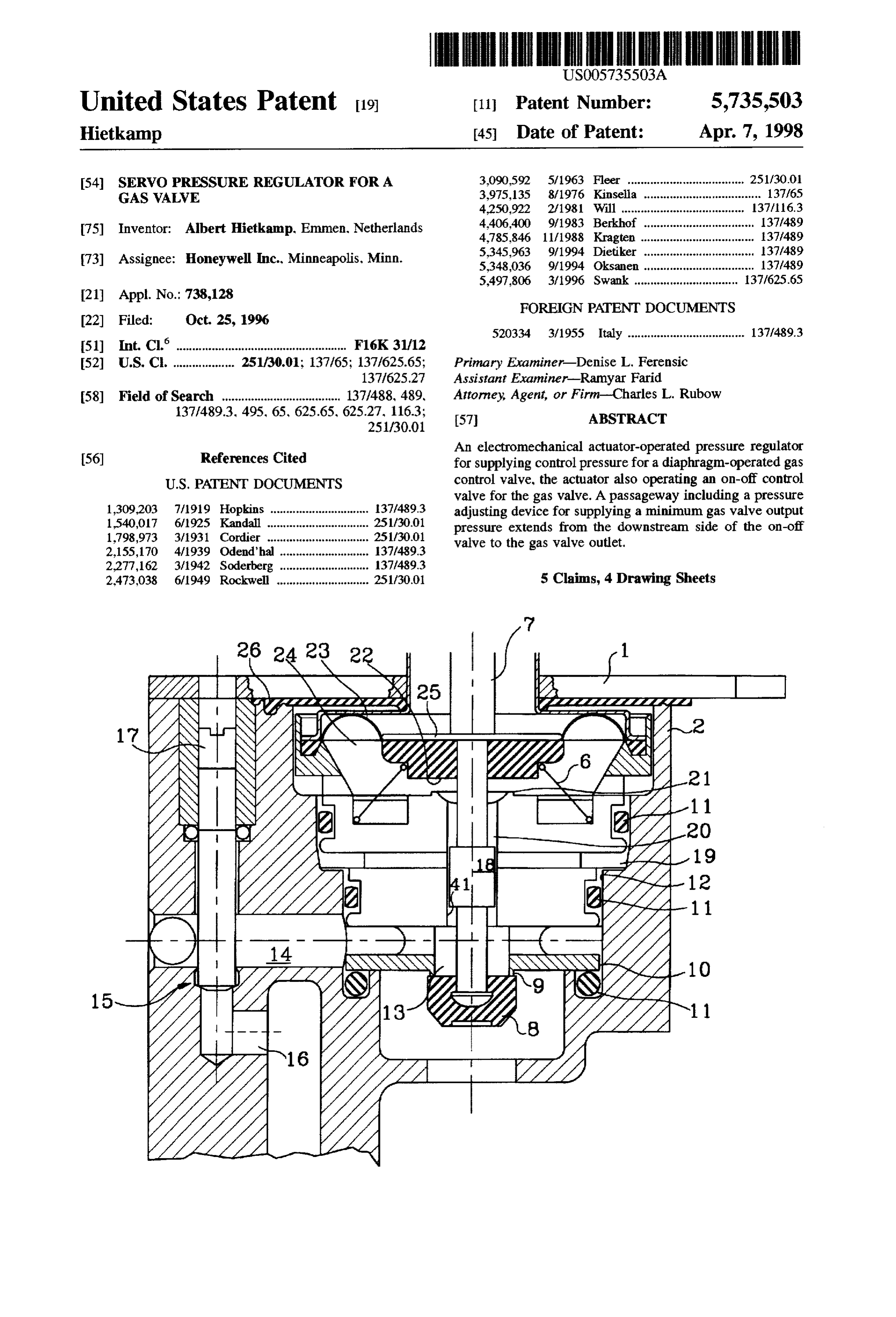
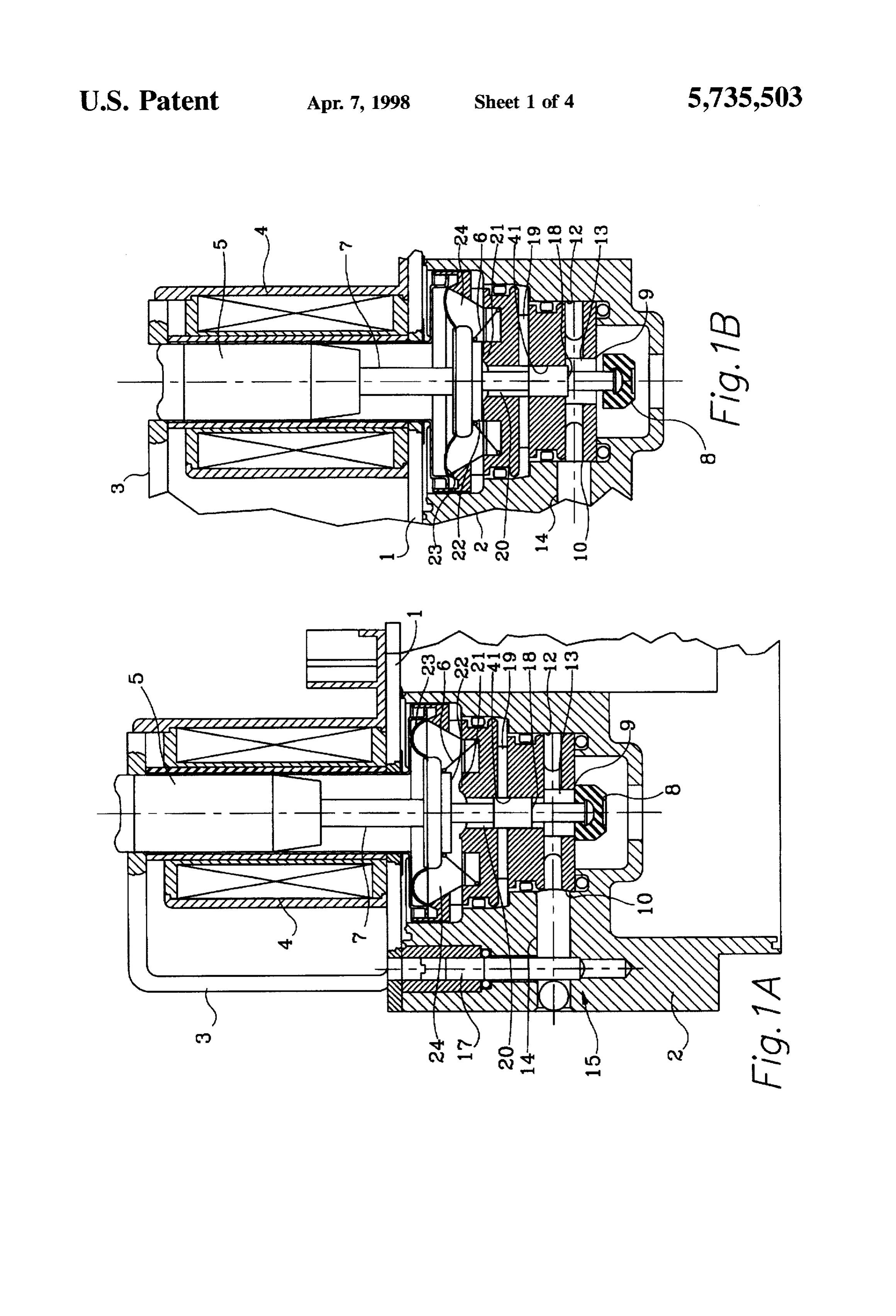
SERVO PRESSURE REGULATOR FOR A BRIEF DESCRIPTION OF THE DRAWTNGS GAS WALWE FIG. 1A is a partial cross-sectional view of a gas valve in BACKGROUND OF THE INVENTION accordance with the Applicant's invention, shown with an The invention generally relates to modulating fuel gas 5 on-off valve in its closed position;
valves, and more specifically to safe, step-opening gas FIG. 1B is a view corresponding to that of FIG. 1B with valves which, after opening, supply a regulated output the on-off valve in its open position;
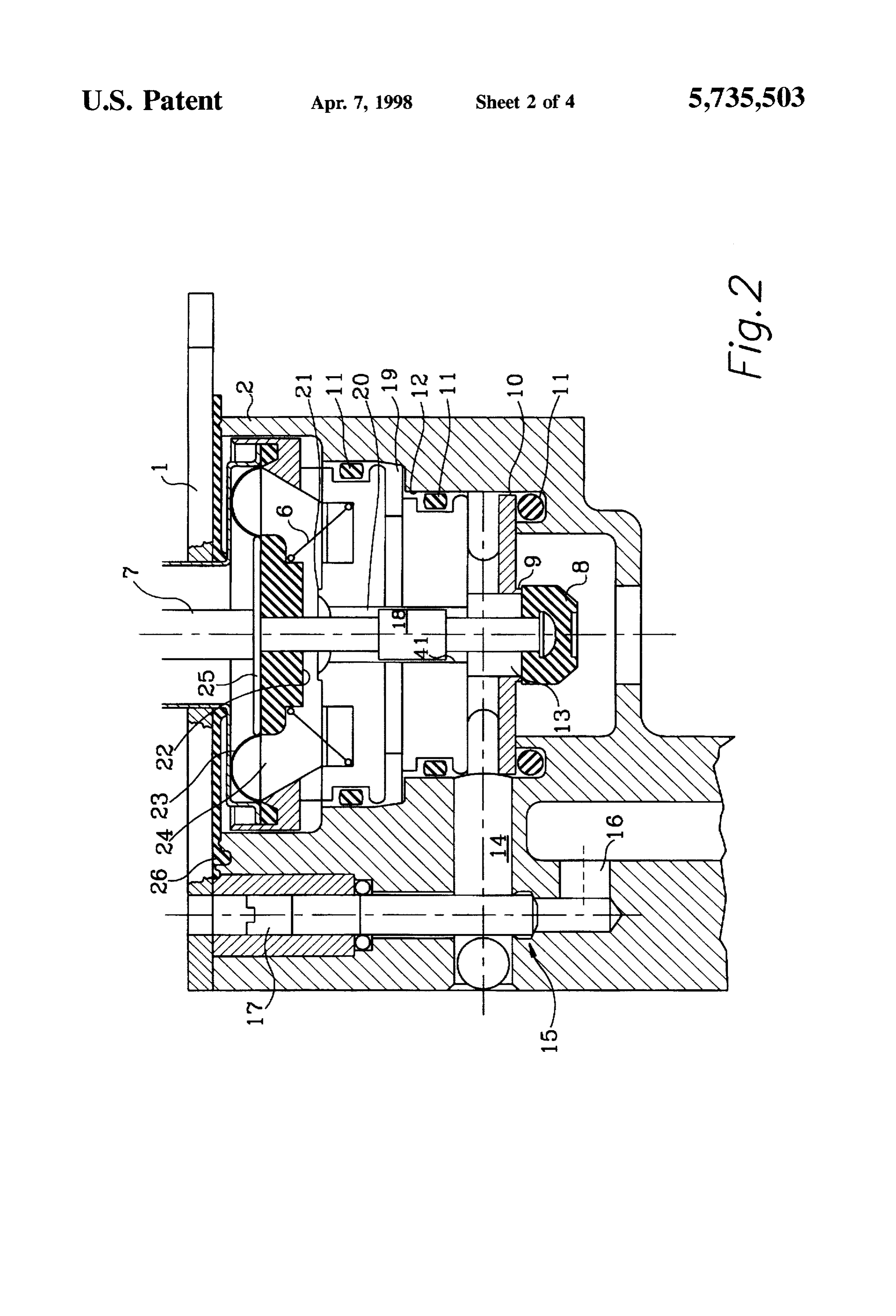
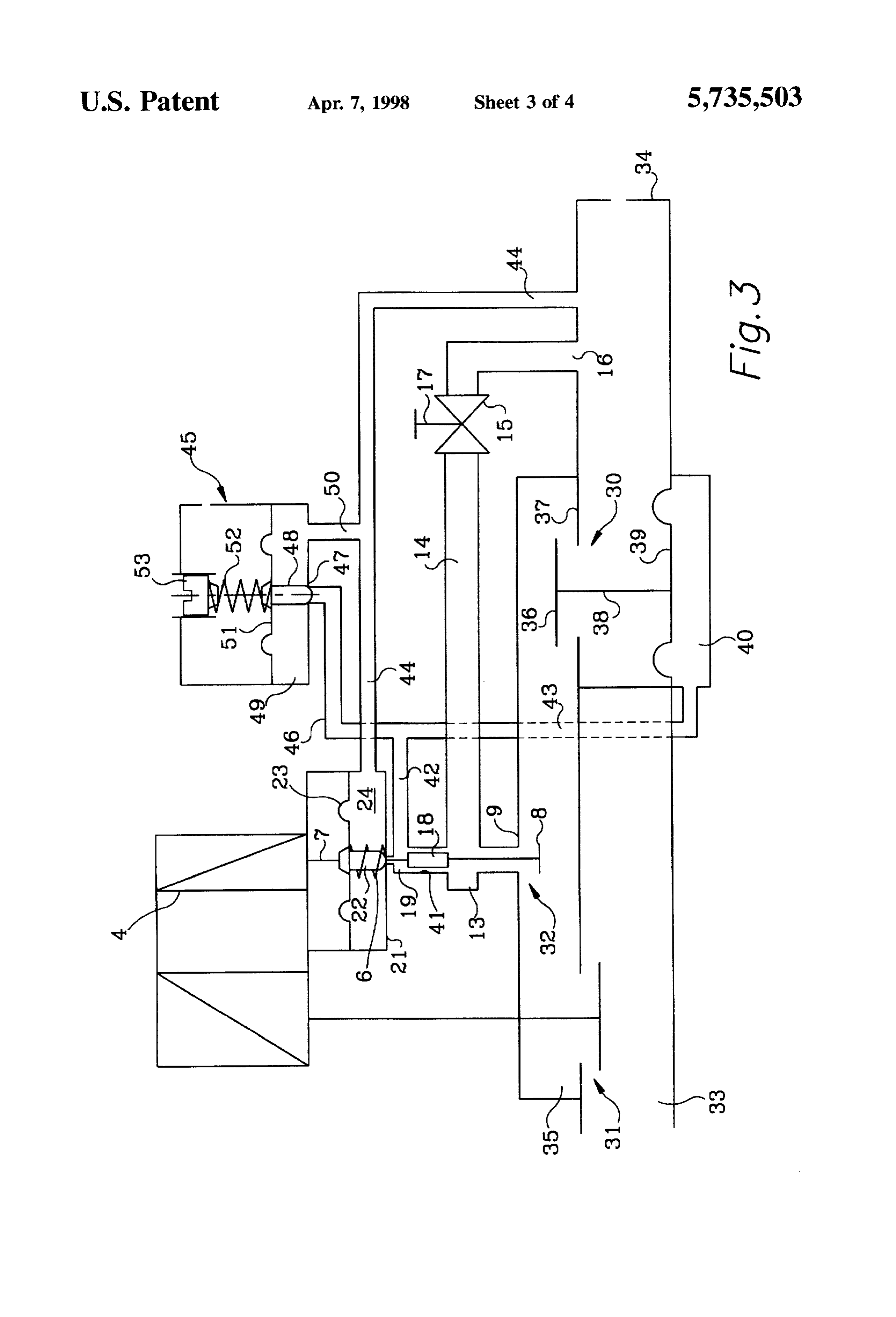
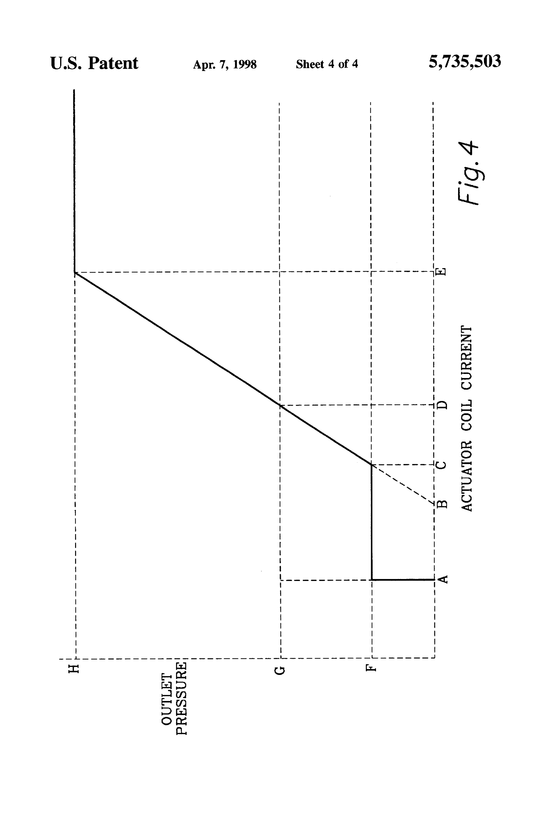
pressure controlled by an electromagnetic actuator which FIG. 2 is an enlarged view of a portion of FIG. 1A; operates a control pressure regulator. FIG. 3 is a schematic representation of a gas valve in European patent 0508 357 discloses a step-opening gas 10 accordance with the Applicant's invention, including a servo valve in which a minimum valve outlet pressure is provided pressure regulator and a diaphragm-operated main gas by a pressure limiting valve which, for minimum gas valve valve; and output pressure, alters the control pressure supplied by a FIG. 4 is a graphic representation of the main valve outlet servo pressure regulator. The pressure limiting valve is in a pressure as a function of current supplied to the coil of an passageway leading to the gas valve outlet. 15 electromagnetic actuator which controls the servo pressure In a further pressure regulator of this type known from regulator,
U.S. Pat. No. 4,785,846, a single electromagnetic operator DESCRIPTION OF THE PREFERRED acts by means of two separate operating levers upon the EMBODIMENT valve stem of an on-off valve and upon the diaphragm of the pressure regulator respectively. In operation, the on-off 20 With reference to the servo pressure regulator of FIGS. valve is opened at the same time a bleed-off passageway 1A, 1B and the enlargement of FIG. 2. an electromagnetic between the main valve outlet and the on-off valve is closed. linear operator is mounted on a cover plate 1 of a valve The passageway has an effect only when switching the main housing. The electromagnetic actuator includes a magnetic valve off. The minimum gas rate required for igniting a yoke 3, a coil 4 and an armature 5 which is axially movable burner flame is provided by the minimum open position of 25 inside the coil. Armature 5 is maintained in the resting the pressure regulator control valve. The minimum open position shown in FIGS. 1A and 2 without current flowing position can be adjusted by means of an adjustable abutment through coil 4 by means of a spring 6, of which one end which cooperates with a stop ring or shoulder on an oper abuts the housing. Although a conical coil spring is ating rod of the regulator. illustrated, a spring of helical or other configuration may be Yet further, German patent application 40 01329 shows 30. equally suitable. The actuator may comprise a stationary coil a gas valve assembly having a diaphragm-operated gas 4, and a movable armature 5 as shown, or a moving coil pressure regulator, a first safety valve upstream of the actuator comprising a stationary magnetic circuit and a regulator and a second safety valve downstream thereof. The moving coil may be employed.
diaphragm of the pressure regulator is influenced by a As shown, a valve stem 7 extends downwardly from the control spring whose bias is mechanically adjustable. In 35 opening through coil 4, and at its lower end carries a closure addition, a control pressure, such as the pressure in a member 8 of an on-off valve. An associated valve seat 9 is combustion chamber, may act upon the diaphragm. The formed by the lower edge of an insert 10 mounted in a pressure regulator generates a control pressure which is stepped through-hole 12 in the valve housing. O-rings 11 supplied to the operating chamber for a pressure-balanced provide a seal between insert 10 and the housing. A first piston valve which is movable within the bores of two walls chamber 13 immediately downstream from the on-off valve of the housing. The valve serve pressure regulator piston and is connected to a channel 16 via a channel 14 and an walls are sized to avoid contact, thereby leaving clearance adjustable orifice or throttle valve 15. Channel 16 is con therebetween. A direct connection is provided between the nected to the main valve outlet passageway. A minimum inlet chamber of the pressure regulator and the outlet cham outlet pressure of the gas valve can be adjusted by means of ber of the main gas valve. This connection is affected by an 45 an orifice adjusting or throttling screw 17. adjustable valve to provide gas flow at an unregulated Valve stem 7. downstream from chamber 13, carries an minimum starting rate immediately after opening safety enlarged cylindrical portion or piston 18, which, in coop valves of the gas valve assembly. Supply of gas at a full eration with the surrounding bore or wall 41, constitutes a regulated pressure begins when said control diaphragm has throttling passageway of predetermined cross-section and moved the piston valve from a resting position into an 50 variable length. The servopressure for the operating cham operating position. ber of the main valve is taken from a chamber 19, Chamber In the past a minimum fuel gas valve outlet pressure of 19 is connected through the throttling passageway to chan about 2 mbar was satisfactory. However, in order to save nel 20 surrounding valve stem 7. Channel 20 terminates at energy, it has become desirable to work with smaller mini a valve seat 21. Valve seat 21 cooperates with the central mum pressures in the order of 0.5 mBar. Conventionally 55 portion 22 of a diaphragm 23 which constitutes a closure generated minimum control pressures are not sufficiently member, Valve stem 7 is held and sealed in the central accurate for such applications. The Applicant has overcome portion 22 of diaphragm 23, e.g. is buttoned into this central this problem by providing a gas valve design in which the portion (see FIG. 2). Spring 6 is pressed at its upper end into minimum control pressure for the main gas valve is taken a surrounding groove of central portion 22 of diaphragm 23. immediately downstream of an on-off valve. Furthermore, A chamber 24 between diaphragm 23 and valve seat 21 is improvement of the pressure regulator is realized in that the connected to a channel 44 as shown schematically in FIG.3. required throttle between the inlet pressure and the servo This channel is in fluid communication with the outlet port pressure chamber of the pressure regulator is provided by 34 of the main gas valve. A diaphragm disk 25 provided on the valve rod of the on-off valve in cooperation with the valve stem 7 constitutes an abutment for the central portion valve rod bore. Thus, a separate channel with a throttling 65 22 of diaphragm 23. A diaphragm-like seal 26 provides a member is not required, which facilitates a simplified struc sealing between the stepped opening of the housing 2 and tural design. cover plate 1.
Page 7
The operation of the pressure regulator now will be balances the force provided by armature 5. When the pres described in connection with the gas control apparatus sure in chamber 19 increases, closure member 22 is lifted schematically shown in FIG. 3 which consists of a main gas further from seat 21 so that a portion of this control pressure valve 30, a safety valve 31 mad a servo pressure regulator in chamber 19 is bled-off to outlet port 34 via channel 44. 32. Gas flows from a supply pipe via inlet 33 into the gas This situation continues until valve 21, 22 closes again when control apparatus and leaves this apparatus through outlet the pneumatic force of the pressure generated in chamber 24 port 34 to which a burner may be connected. The servo acting on diaphragm 23 equals the force which armature 5 pressure regulator is supplied with gas when safety valve 31 transmits to valve stem 7. Since the minimum gas rate is is open. The structure and operation of such safety valves are solely determined by the position of throttle valve 15, and known. In FIG. 3 all valves are shown in the open positions 10 does not depend on the state of the servo controller, a very although when in resting position they are actually closed by small minimum pressure can be achieved at outlet port 34. return springs (not shown). In FIG. 4 the pressure at outlet The accuracy of this minimum pressure is affected by the port 34 of the gas control apparatus is shown as a function pressure at inlet 33. However, since pressure changes at the of the current supplied to actuator coil 4. inlet appear reduced by the relation of inlet-to-outlet pres As soon as gas enters space 35 below on-off valve 8, 9 via 15 sure behind throttle valve 15, these changes are very small. safety valve 31, the burner cycle may be initiated. For this For limiting the maximum pressure H at outlet 34 a purpose a current is fed to coil 4 of the actuator and produces pressure limiter 45 is provided which is connected to control a magnetic field which exerts a force on armature 5. This pressure chamber 19 of the regulator via channels 46 and 42 force is transmitted to closure member 8 to move it down which are also connected to operating chamber 40 of main ward. As soon as this current exceeds a minimum value A 20 valve 30. If the pressure in channel 46 increases too much, (see FIG. 4), closuremember 8 is lifted from valve seat 9 and this pressure is bled-off via the valve of the pressure limiter moves into the open position as shown in FIG. B. With 45 consisting of valve seat 47 and closure member 48. For on-off valve 8, 9 opened, gas flows into chamber 13. From this purpose pressure chamber 49 of the pressure limiter is there a minimum gas pressure Freaches outlet 34 of the gas connected via a channel 50 to a further channel 44 which control apparatus via channel 14, throttle valve 15 which 25 leads to the outlet. The maximum pressure level can be provides an adjustable minimum outlet pressure, and chan adjusted to a desired value by means of a spring 52 and an nel 16. From there this pressure is applied to the burner. associated adjustment screw 53. As soon as the energizing The main gas valve consisting of closure member 36, current exceeds value E, the outlet pressure is limited to its valve seat 37, valve stem 38, diaphragm 39 and operating maximum value H.
chamber 40 remains closed under the influence of a return If, because of an increasing demand for heat from the load spring (not shown). The piston-like enlargement 18 of valve heated by the burner, e.g. a space heating apparatus or a hot stem 7 in connection with wall 41 surrounding said piston water supply apparatus, the gas flow to the burner is to be constitutes a throttling member which pneumatically sepa increased, main valve 30 must be opened further which rates chamber 19, exposed to the servo pressure, from means that the control pressure within operator chamber 40 chamber 13. exposed to the inlet pressure. When on-off on 35 must also be increased. For this purpose a higher current is valve 8, 9 is opened by actuator 3, 4, 5, the valve stem is supplied to actuator coil 4 so that valve rod 7 is pressed moved downward until throttling piston 18 completely dips downwards with an increased force. Bleed valve 21, 22 into bore 41. Via open on off valve 8, 9 and throttling therefore opens at a higher pressure under diaphragm 23, passageway 18, 41, gas is supplied to chamber 19 where a such pressure being the pressure in chamber 19 which, via control pressure is slowly built up as a result of closure of bore 20, acts on closure member 22 of the bleed valve. The bleed valve 21, 22. This control pressure is fed to operating value of the control pressure, increased in the above chamber 40 of main valve 30 via channels 42 and 43. described manner, again is given as mentioned above by the As soon as the force generated by the control pressure force balance at valve stem 7. If the gas flow to the burner within operating chamber 40 and acting upwardly on dia is to be decreased, the energizing current for the solenoid is phragm39 exceeds the force of the return spring (not shown) 45 reduced so that bleed valve 21, 22 opens at a lower control acting downwardly on diaphragm39 together with the force pressure. As this control pressure decreases the position of generated by the inlet pressure on top of closure member 36, main valve closure member 36 is moved toward valve seat diaphragm 39 moves valve stem 38 upwardly and lifts 37.
closure member 36 from valve seat 37. Then gas flows from For adjusting the minimum gas pressure, e.g. For G at inlet 33 via chamber 35 and through main valve 30 to outlet 50 outlet 34, the force of spring 52 acting on diaphragm 51 is port 34 with a flow rate which is determined by modulating reduced to zero. No control pressure can then build up in pressure regulator 32 shown in detail in FIGS. 1 and 2. chamber 19. Main valve 30 remains closed under the influ Depending on the minimum gas pressure, e.g. For G in FIG. ence of its return spring (not shown). All pressure within 4, as adjusted by means of throttle valve 15, this modulating chamber 19 is bled off to outlet port 34 via open valve 47. pressure starts at actuator current value Cor Din FIG. 4. The 55 48. The outlet pressure then is determined by throttle valve higher the adjusted minimum pressure is, the stronger the 15. Accordingly, it can be adjusted by means of throttling energizing current must be in order to provide a linear screw 17 to provide the minimum gas pressure. increase in outlet pressure. Current valve B corresponds to Although a particular embodiment has been shown and the starting point of the linear pressure increase resulting described for illustrative purposes, various modifications from the force acting through valve stem 7. In addition, the and other embodiments within the Applicant's teachings will above-discussed minimum gas rate flows via channels 14 be apparent to those of ordinary skill in the relevant arts. It and 16 to outlet port 34. Opening of on-off valve 8, 9 at a is intended that coverage not be limited to the embodiment predetermined current value Aisindependent from the curve shown, but only by the scope of the following claims. of the modulating characteristic B-E of the servo pressure The embodiments of the invention in which an exclusive regulator. 65 property or right is claimed are defined as follows: The control pressure generated in chamber 19 is also 1. In a pressure regulator for generating a control pressure applied to the bottom side of diaphragm 23 and there for a diaphragm-operated gas valve which controls gas flow
Page 8
through a first passageway between an inlet and an outlet, 2. The pressure regulator of claim 1 wherein said valve the pressure regulator being of the type in which the control stem is formed with an enlarged cylindrical section in the pressure is determined by an electromagnetic operator which region of the bore, the width and the length of the gap operates a bleed valve including a first closure member between the cylindrical section and the wall of the bore carried on a valve stem and an on-off valve including a 5 determining the throttling action.
second closure member carried on the valve stem, the 3. The pressure regulator of claim 2 wherein: improvement which comprises: said housing assembly includes an insert having the bore a second passageway for supplying gas at an unregulated therethrough, the bore being aligned with a central axis minimum pressure from the inlet to the outlet of the and terminating at opposite ends in first and second diaphragm-operated gas valve, said second passageway 10 valve seats which respectively cooperate with said first including means for adjusting the unregulated mini and second closure member to form the pressure regu mum pressure the on-off valve being arranged to con lator and said on-off valve respectively, the enlarged trol gas flow through said second passageway; and cylindrical section being located between the first and a throttling device located downstream of said second 15 second closure members, said second passageway passageway for supplying gas from the downstream intersecting the bore at a location between said first side of said on-off valve to the bleed valve, said closure member and the enlarged cylindrical section of throttling device being formed by a gap between the said valve stem; and valve stem and a surrounding wall of a bore in a the pressure regulator includes a channel opening from housing assembly in which the diaphragm operated gas 20 the bore between said throttling device and the bleed valve is formed, said valve stem being positioned to valve for supplying the control pressure from the extend through the bore, wherein a first pressure cham pressure regulator to the diaphragm-operated gas valve. ber is defined in the housing assembly and is fluidly 4. The pressure regulator of claim 3 wherein: coupled to said second passageway, a second pressure said housing assembly includes a valve housing formed chamber is defined in the housing assembly down 25 with a through hole of stepped diameter aligned with stream of the first pressure chamber a control chamber the central axis; and of the diaphragm-operated gas valve being fluidly said insert is of circular cross section perpendicular to the coupled to the second pressure chamber by a third central axis, and of generally stepped diameter corre passageway, and a third pressure chamber is defined in sponding to the stepped diameter of the through hole. the housing assembly downstream of the second pres 30 5. The pressure regulator of claim 4 wherein said third sure chamber and is fluidly coupled to a fourth pas chamber is defined in part by a flexible diaphragm fixed to sageway that bleeds excess pressure to the outlet of the said valve stem and forming a fluid tight seal between said gas valve, the first closure member being located in the valve stem and said housing assembly. third chamber, the first second and third chambers being separated by partitions of the housing assembly. :: *k sk. : ::
Page 9
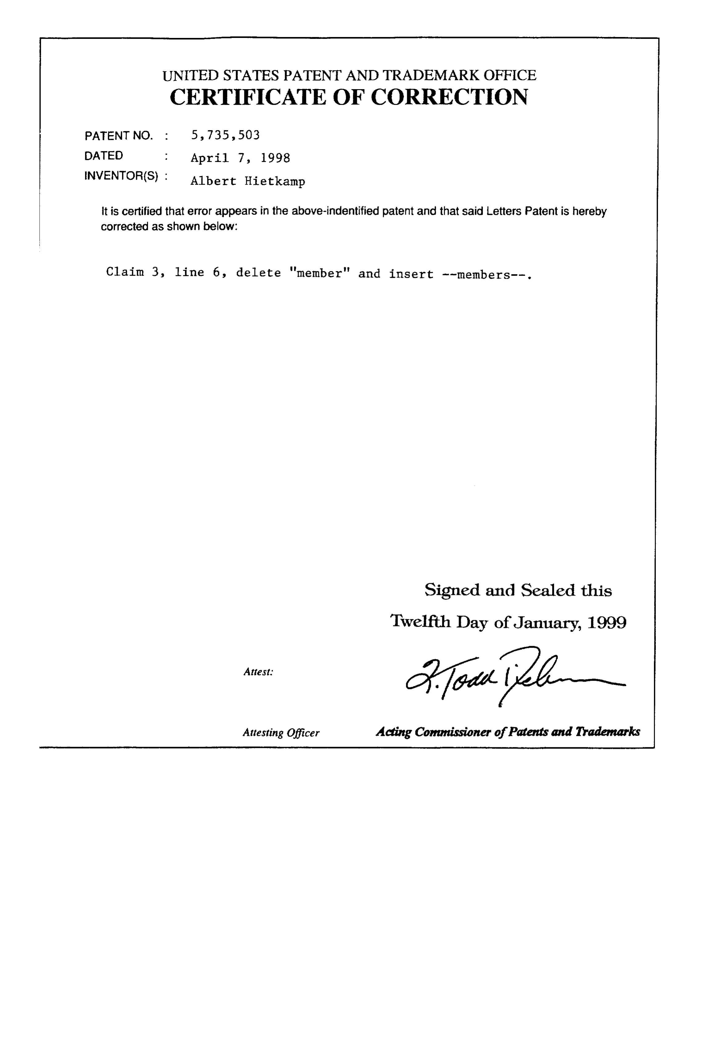
UNITED STATES PATENT ANDTRADEMARK OFFICE
CERTIFICATE OF CORRECTION
INVENTOR(S) : Albert Hietkamp it is certified that error appears in the above-indentified patent and that said Letters Patent is hereby corrected as shown below:
Claim 3 line 6, delete "member" and insert --members--. Signed and Sealed this
Twelfth Day of January, 1999
Attesting Officer Acting Commissioner of Patents and Trademarks
Provenance
- Collection
- Cited prior art
- Original PDF
- patentimages.storage.googleapis.com →
- Filed
- 1996-10-25
- Pages
- 9
- Method
- pdftotext (the PDF's own text layer) + pdftoppm 300dpi page scans
- Source
- Google Patents bibliographic record
- Granted
- 1998-04-07
- Inventors
- Albert Hietkamp; Honeywell Inc
- Transcribed from
- patentimages.storage.googleapis.com →