patent · US3172460
Ribbon burner assembly
9 March 1965
Page 1
Drawing sheet — no readable text.
Page 2
Drawing sheet — no readable text.
Page 3
Drawing sheet — no readable text.
Page 4
United States Patent Office 3,72,460 Patented Viar. 9, 1965
FIGURE 9 is a considerably enlarged, fragmentary 3,172,460 top plan view illustrating the specific construction of the RBON BURNER ASSE/SELY burner ports.
Hirann E. Tempie and Henry W. Bremer, Sagiaaw, Mica., FIGURE 10 is a sectional view of a modified valve assignors to Baker Perkins ine, Saginaw, Michi, a cost 5 spring assembly.
poration of New York Referring now more particularly to the accompanying Fied Nov. 24,596, Ser. No. 54,742 drawings in which only a preferred embodiment of the
invention is illustrated, a letter W generally indicates the
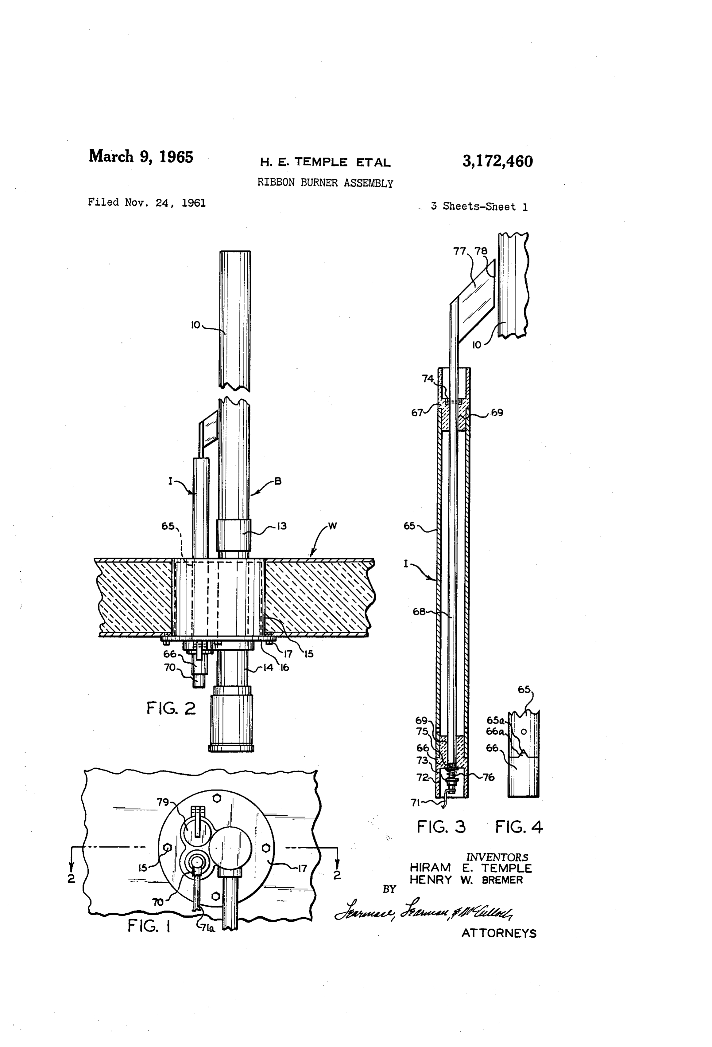
This invention relates to improvements in gas burners insulated wall of an enclosed baking oven of conventional of the type which burn a premixed combustible hydro O design which includes top and bottom walls as well as carbon gas and air mixture, usually under an appreciable side walls and is of a type used in the baking of bread pressure to meet the exigencies of both industrial and and other farinaceous products. The invention is con domestic uses. The present invention is particularly con cerned with the gas burner construction generally desig cerned with a burner for use in the baking ovens of nated B which is supported in position on a side wali of commercial bakeries and is of the type which includes an 5 the oven and includes a tubular casing member 80 pro extremely elongate burner housing or barrel having lon jecting iongitudinally into the oven usually transversely gitudinally spaced burner ports therein. of the length thereof. In the conventional installation a One of the prime objects of the invention is to pro plurality of longitudinally spaced apart burners B will vide a burner assembly, incorporating multiple fuel dis be employed and, as noted previously, it is one of the tribution tubes of varying length, which includes inde 20 prime purposes of the present invention to provide a pendent means for varying the flow of gas to each tube burner construction which is so constituted as to be capa from a common source so that temperature Zones within ble of creating heat zones within the oven. A typical the oven may be readily adjusted. The construction per installation showing a tunnel oven of considerable length mits a baker to selectively increase or decrease the gas and in which a large number of burners are used in flow to a particular portion of the burner barrel to pro 25 transverse disposition is shown in Patent No. 2,801,686 vide the desired lateral heat to a particular zone in the and this disclosure is herein incorporated by reference so OWe that no fuither disclosure of the oven elements is nec A further object of the invention is to provide a burner essary.
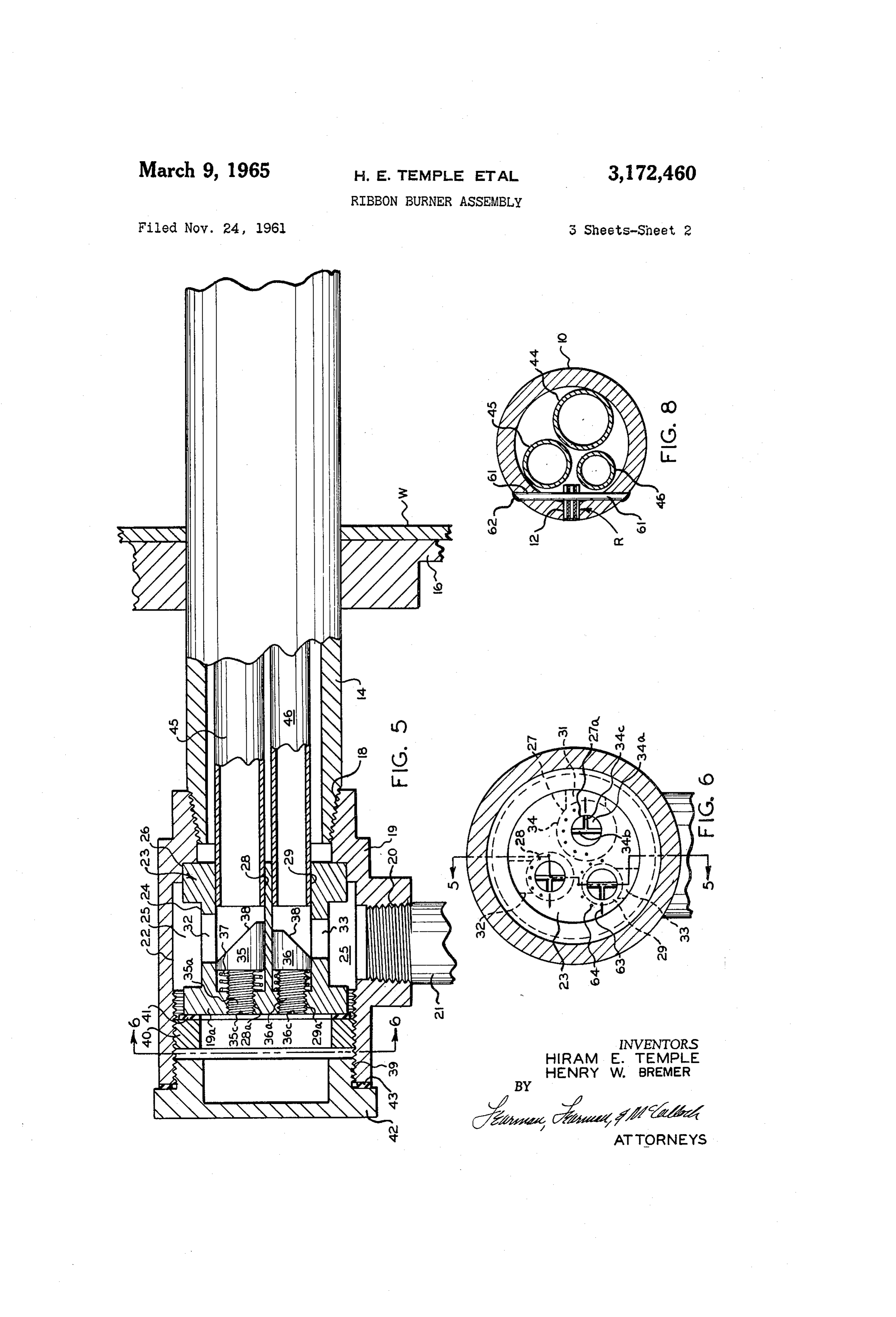
assembly of the character described which is so con The burner casing or barrel 9 is closed at its inner structed that the burner can function interchangeably as 30 end by an end wall is as shown in FIGURE 7, and a a left or right hand burner to provide proper heat and longitudinally extending slot 12 is provided in one of fame direction within the oven. its sides in the usual manner for accommodating the port Another object of the invention is to provide a burner forming ribbon assembly members generally designated construction, including metering or proportioning mem R which will be presently described. At its outer end bers for delivering gas to different portions of a given 35 adjacent the side wall W, burner casing () is coupled burner, which are so constructed that a fine control of by sleeve 3 to a housing section 4 which is fixed within the flow of gas is provided. a burner box 5 extending through an opening in the Still another object of the invention is to provide a wall W and incorporating a cover-plate 6 which can be very efficient and highly reliable ribbon burner of rela secured to wall W by cap screws 17. Provided on the tively simple construction which can be very economically 40 outer end of casing i4 are threads 8 which mount a manufactured and assembled. manifold enclosure or fitting 9 having a threaded open Other objects of the invention will become apparent ing 20 receiving a gas supply tube 21. It is to be under from the accompanying description and appended claims. stood that the gas supply tube 2 provides a pre-mixed In the drawings: hydrocarbon gas and air mixture under a predetermined FIGURE 1 is a front elevational view showing the rib pressure from any suitable conventional source. bon burner construction as mounted in place on an oven The interior of fitting 19 is bored as at 22 to receive wall. fuel gas from tube 2 and mounts an interior gas dis FIGURE 2 is a top plan view of the construction taken tributing manifold sleeve or housing 23 which is annu on the line 2-2 of FIGURE 1. larly grooved as at 24 so that an annular, gas receiving FIGURE 3 is a sectional plan view through the elec 50 manifold fuel chamber 25 of substantial size is provided trode housing only. within fitting 9. Manifold sleeve 23 is received within FIGURE 4 is a fragmentary plan view of one end of and located by a reduced bore portion 26 of fitting 9 the electrode housing. as shown and in the form of the invention shown includes FIGURE 5 is an enlarged, partly sectional, elevational three separate openings 27-29 which are of different di view taken on the line 5-5 of FIGURE 6 and illustrating ameter for a purpose which later will become apparent. the metering members which control the distribution of Passages 27-29 include reduced diameter threaded bore gas to various sections of the elongate burner assembly. Sections 27a-29a, which extend through the otherwise FIGURE 6 is a sectional, elevational view taken on closed front wall 9a of fitting 9 as shown in FIGURE the line 6-6 of FIGURE 5. 5. Provided in the peripheral wall of manifold sleeve 23 FIGURE 7 is a partly sectional, top plan view showing J are circular ports 32-33, each of which separately com the gas distributing tubes in assembled position within municates fuel receiving chamber 25 with passages 27-29, the burner barrel. respectively.
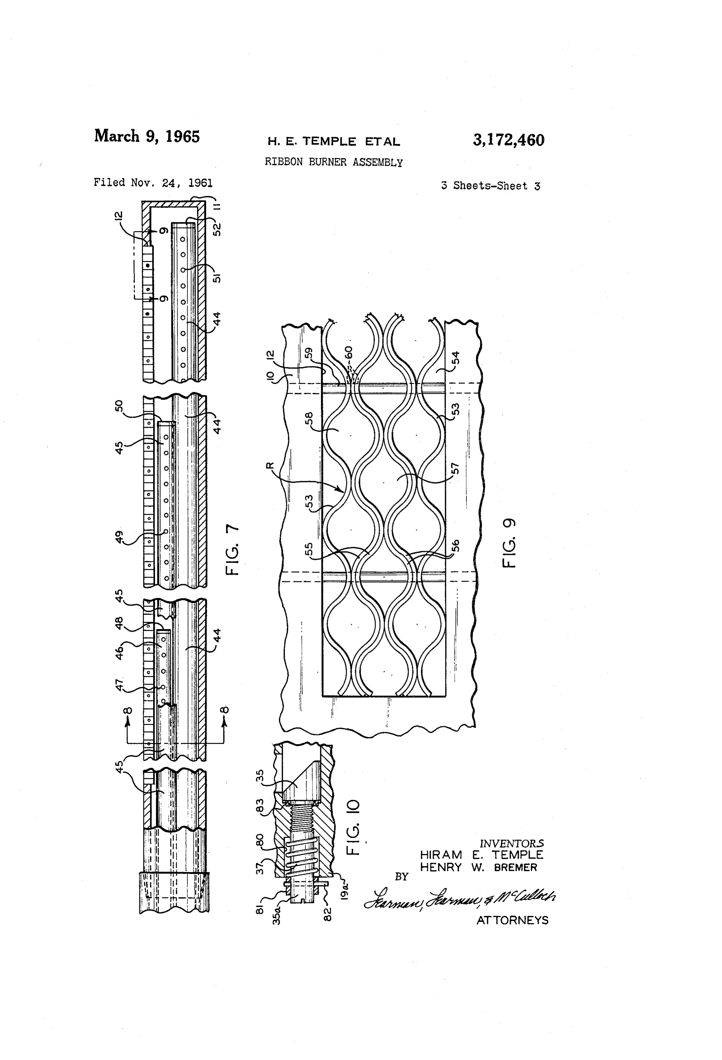
FiGURE 8 is an enlarged, cross sectional view taken In order to provide a fine metering adjustment of the on the line S-8 of FIGURE 7. gas flow through orifices 31-33 a trio of metering men
Page 5
bers 34-36 are respectively mounted in the passages 27 wire 71 may be provided to fit within the bore 72 of bush 29. These members 34-36 which include threaded shank ing 66 and a wire sheath 71a leads from conduit 70. It portions 34a-36a as shown, are slotted at their ends as will be seen that bushings 66 and 67 may include projec at 34b-36b so that an ordinary screw-driver may be used tions 66a which are received in openings 65a provided in to revolve members 34-36. Coil springs 37 provided sleeve 65 so that the bushings are prevented from rotat between the members 34-36 and front wa119a of the ing relative to the sleeve 65. manifold sleeve 23 prevent any play in the threaded pas Provided on the rod 68 is a fixed washer 73, a fixed sages 27a-29a and the mating threaded shank portions washer 74, and a washer 75 which is slideably received 34a-36a from affecting the adjustment. Members 34-36 on the rod 68 and furnishes an abutment for a coil spring are cylindrical pieces which have a corner cut off as at O 76 which holds the rod 68 in assembled position in the 38 so that a very fine metering adjustment of the flow usual manner. Rod 68 uniquely provides on its inner end of the gas through ports 31-33 can be obtained. a flag-shaped plate 77 having an edge 78 parallel with It will be seen that the enclosing means or fitting 19 is barrel 10 adjacent to the ribbon assembly R. With cur rent being impressed continuously upon rod 68, sparks also threaded as at 39 to receive a manifoid sleeve retain ing ring 40 including sealing gasket 4, and a cap 42, in continuously jump the gap between edge 78 and the burner cluding a sealing gasket 43, which can be easily removed B and a wide area sparking surface is provided. While to obtain access to the metering members 34-36. From it is of no importance to the present invention, the mem the passages 27-29 in manifold sleeve 23 the gas is deliv ber designated 79 in FIGURE 1 is a pivotally mounted ered in metered quantity to the distribution tubes 44-46 peep-hole cover which in the usual manner can be swung seating in the inner ends of passages 27-29, respectively, 20 upwardly to permit viewing through an opening in the which feed the fuel to different lengthwise sections of the wall W.
burner barrel 10. As shown particularly in FIGURE 7, In FIGURE 10 a modified metering member is shown the smaller diameter tube 46 terminates in the front por in which the manifold sleeve front wall 19a is counter tion of burner barrel 10 at a point about one fourth of the bored as at 80 to accommodate the spring 37 which exerts length of barrel 0 and includes spaced apart gas issuing pressure on a collar 81 secured to the stem portion of the openings, 47, the end of the tube being provided with a metering member. While only the metering member 35 plug insert 48 which also acts as a spacer. Tube 45ter is illustrated in FIGURE 10, it is understood that the other minates at a point about three fourths of the length of metering members are formed and mounted in exactly barrel 10 and includes gas issuing ports 49 and an end the same manner in this modification of the invention. plug 50. Provided in distributing tube 44 which extends Collar 81 may be anchored in position by a pin 82 which substantially to the end wall 11 of the burner barrel 10 are extends through the stem portion 35a and which has an extending end which can serve as a reference in place of gas issuing ports 51 and an end plug 52.
As indicated particularly by FIGURE 8, the burner B slot 35c. In this embodiment of the invention, packing shown is a so-called left hand burner in which the ribbon 83 is provided to seal the assembly and no cover plate 42 orifice 12 is leftwardly disposed. However, clearly the is necessary. The spring 37 tends to force the collar 81 burner could be rotated through 180 so that the slot 12 OutWardly and so takes up any play in the threaded por is rightwardly disposed or through 45 so that it would be tion of the stem 35a.
possible to issue the flames upwardly or downwardly, as In operation, the gaseous fuel mixture proceeding desired. Mounted within the slot 12 is the ribbon assem through supply pipe 2 is received within the chamber 25 bly generally designated R which is, in the present in 40 and enters the passages 27-29 through orifices 31-33. stance, formed from identically corrugated strips which The flow of gas to distributing pipes 44-46 is governed by can be readily and economically formed with a single die the position of metering members 34-36. Each of these member. As shown in FIGURE 9, ribbon assembly R metering members 34-36 is independently adjustable includes outer strips 53 forming reduced size passages 54 through a half a revolution to increase or decrease the between the marginal side walls of slot 2 and the inward size of the orifices 31-33. Different temperature zones ly projecting corrugations of the strips 53, and nested pairs are often to be found in ovens because of draft conditions of oppositely disposed central strips 55 and 56 which form and to provide optimum baking conditions for various increased size ports 57 which are centrally disposed, and products it will be possible, of course, to initially set the equal sized ports 58 which are formed between the outer members 34-36 so that flames of different size are prop of the strips 55 and 56 and the strips 53. As shown partic 50 agated at the burner, ports of the ribbon assembly R ularly in FIGURES 8 and 9, the strips 53, 55 and 56 are to achieve uniformity. Further, it will be possible to finely so arranged that their corrugations abut alternately and vary the gas flow through any of the tubes 44-46 during pins 59 can be inserted through openings 60 provided in the baking cycle, if desired.
them. Bored in the casing 10 as shown in FIGURE 8 are The ribbon assembly R provides relatively high velocity gas passages and relatively low velocity gas passages pro aligned openings 61 to receive the pins 59 which can be 55 viding welded in position by weldment material 62. long flames extending to points remote from the In addition to the slots 34b-36b each metering mem burner and relatively short pilot flames immediately adja ber 34-36 includes indicator slot portions 34-c-36c which cent the burner, the relatively short pilot flames serving when aligned with lines 63 provided on the face of meter to maintain the longer flames ignited since the latter flames ing member 23 indicate that the metering members 34-36 60 to may be produced by gas moving at such high velocity as are in fully opened position. The circularly arranged dots exceed the flame propagation rate of the mixture. The 64 which are provided on the front face of the manifold. tendency of the spark jumping the gap between the edge sleeve 23 indicate more nearly closed positions of the 78 and ribbon assembly R is to travel up and down the orifices 31-33. The endmost dot proceeding from line 63 edge 78 to thereby provide a wide area sparking surface indicates the most nearly closed position of the metering 65 which does not readily erode.
members 34-36 beyond which the slot 34c should not be It is to be understood that various changes may be made turned. in the construction shown and described to effectuate the The burner B also includes a continuous igniter unit Same or similar results without departing from the spirit generally identified by the letter which includes a casing of the invention or the scope of the appended claims. The or housing 65 extending through an opening in the wall 70 foregoing descriptive matter and drawings are intended W and insulating end bushings 66 and 67 as shown. The only as illustrative and the invention is defined by the sleeve 65 is, like the sleeve 14, fixed to cover-plate 16 and claims. - houses an ignition rod 68 in the usual manner which is We claim:
slideably received in openings 69 provided in the bushings 1. In a ribbon burner construction for an oven; an 66 and 67. An elbow conduit 70 for the current carrying 75 elongate, tubular member having longitudinally extend
Page 6
ing burner ports; a manifold means mounted on one end tributing tube communicating with each passage and ex of said tubular member and including a plurality of tending into said housing, having opening means at dif separated, longitudinally extending passages; said mani ferent locations longitudinally within said tubular housing fold means having separate peripheral openings leading to deliver fuel gas to different sections of said burner port radially separately to each passage; means supplying gas 5 means; the opening means of each tube comprising longi to said openings; a plurality of distributing tubes of dif tudinally spaced apart ports for uniformly supplying ferent length extending within said tubular member and fuel gas over the length of said burner port grid means; open near one end to said manifold passages and near said manifold sleeve having separate orifice means com their opposite ends to different longitudinally spaced municating said gas receiving chamber with each passage; apart sections of said tubular member; and a rotatably 0. and metering means radially opposite each orifice means adjustable metering screw including a spring biased outer adjustable in each passage relative to said orifice means shank extending through the manifold means and a meter to vary the flow therethrough to said distributing tubes ing head with an inclined face in radial alignment with and provide variable heat zones in the oven. each peripheral opening varying the flow through each 5. In an oven; a ribbon burner construction compris peripheral opening in said manifold means to each of 5 ing: an elongate, tubular housing having longitudinally said distributing tubes selectively to provide variable extending burner port grid means over much of its length; heat zones in an oven or the like. a fitting at one end of said tubular housing including port 2. In an oven; a ribbon burner construction compris means for admitting fuel gas to the fitting; a manifold ing an elongate, tubular housing having longitudinally sleeve within said fitting and perimetrally spaced there extending burner port grid means over most of its length; 20 from to form a fuel gas receiving chamber between said a fitting at one end of said tubular housing including a manifold sleeve and fitting communicating with said port port for admitting fuel gas to the fitting; a manifold sleeve means; said manifold sleeve having a plurality of sep within said fitting including a portion between its ends arated, longitudinally extending passages of different di of less diameter than said fitting forming a fuel gas re aneter; a plurality of peripherally spaced apart dis ceiving chamber between said portion of the manifold 25 tributing tubes, including a separate distributing tube com sleeve and fitting; said manifold sleeve having a plurality municating with each passage and projecting into said of separate, longitudinally extending passages from one housing, having opening means at different locations end thereof to the other; a separate distributing tube longitudinally within said tubular housing to deliver fuel extending into each passage and projecting therefrom gas to different sections of said burner port means; the through said housing to terminate at different locations 30 opening means of each tube comprising longitudinally longitudinally within said tubular housing and deliver spaced apart ports, for uniformly supplying fuel gas over fuel gas to different sections of said burner port means; the length of said burner port grid means, which are each tube having longitudinally spaced apart ports for angularly displaced relative to said burner port means; uniformly supplying fuel gas over the length of said burner said manifold sleeve having separate orifice means com port means; said manifold sleeve having separate orifice municating said gas receiving chamber with each passage; means communicating said gas receiving chamber with and an independent metering means axially adjustable each passage, and metering means radially opposite each in each passage relative to said orifice means to vary orifice means adjustable in each passage relative to said the flow therethrough to said distributing tubes and pro orifice means to vary the flow therethrough to said dis vide variable heat zones in the oven. tributing tubes and provide variable heat zones in the w 6. A ribbon burner construction for an oven compris OWen. ing: an elongate, tubular member having longitudinally 3. In an oven; side walls; a ribbon burner construction extending burner port means; manifold means including comprising an elongate, tubular housing extending in housing means mounted at one end of said tubular mem. wardly from a side wall and having longitudinally extend ber and including a plurality of separated, longitudinally ing burner ports over most of its length within said oven; extending passages; said housing means having separate a fitting at one end of said tubular housing outside said peripheral openings leading radially separately to each side wall including a port for admitting fuel gas to the passage; said manifold means also including enclosing means perimetrally spaced from said housing means to fitting; a manifold sleeve within said fitting perimetrally provide spaced therefrom to form a fuel gas receiving chamber be a fuel gas receiving chamber means therebetween tween said portion of the manifold sleeve and fitting; 50 surrounding said openings; means for supplying fuel to Said chamber means; a plurality of distributing tubes ex said manifold sleeve having a plurality of separate, lon gitudinally extending passages from one end thereof to tending within said tubular member and Open near one end to the passages in said housing means, the tubes being the other; a separate distributing tube extending into each also Open at differently spaced longitudinal distances from passage and projecting therefrom through said housing to terminate at different locations longitudinally within 55 said housing means to different longitudinal sections of said tubular member; and adjustable metering head said tubular housing and deliver fuel gas to different means, in radial alignment with each peripheral open sections of said housing; said manifold sleeve having ing in the housing means, disposed radially inwardly separate orifices communicating said gas receiving cham ber with each passage; and a metering screw rotatably thereof for varying the flow through each peripheral opening to each of said distributing tubes selectively to adjustable in each passage relative to an orifice, having 60 provide variable heat zones in the oven. a cylindrical metering head with an inclined surface radially opposite the orifice to vary the flow through each 7. A ribbon burner construction for an oven compris orifice to said distributing tubes and provide variable ing: an elongate, tubular member having longitudinally heat zones in the oven. extending burner port means; wall portions forming a 4. In a ribbon burner construction: an elongate, tubu 65 fuel chamber at one end of said tubular member and a lar housing having longitudinally extending burner port plurality of distributing tubes extending within said tubu grid means over much of its length; a fitting at one end lar member, the tubes being open at differently spaced of said tubular housing including port means for admit longitudinal distances from said fuel chamber to different ting fuel gas to the fitting; a manifold sleeve within said longitudinal sections of said tubular member; there be fitting, including a portion between its ends of less di 70 ing a series of perimetrally spaced openings, surrounded ameter than said fitting forming a fuel gas receiving perimetrally by said fuel chamber, leading radially sep chamber between said portion of the manifold sleeve and arately from said fuel chamber through said wall portions fitting communicating with said fuel gas admitting port to communicate with each tube separately; means for means; said manifold sleeve having a plurality of sep Supplying fuel to said fuel chamber; and adjustable arate, longitudinally extending passages; a separate dis 75 metering head means, in radial alignment with each periph
Page 7
eral opening, disposed radially inwardly thereof for vary- 2,318,408 - 5/43 Miess ---------------- 317-83 ing the flow through each opening to each of said distrib- 2,353,865 7/44 Armstrong ------------ 158-118 uting tubes selectively to provide variable heat Zones in 2,443,101 6/48 Flynn et al. -------- --- 158-116 the oven. 2,759,531 - 8/56 Anthes --------------- 158-118 References Cited by the Examiner 5 -
UNITED STATES PATENTS FOREIGN PATENTS 925,808 - 6/09 Heft. 338,806 11/30 . . Great Britain. 1:72. 8/29 R as a a a a a rur 6. JAMES W. WESTHAVER, Primary Examiner. 1,715,248 5/29 Reynolds -------------- 158-99 O FREDERICK L. MATTERSON, JR., MEYER PERLIN, 1,789,226 1/31 Ensign et al. ----------- 158-99 Examiners.

Provenance
- Collection
- Cited prior art
- Original PDF
- patentimages.storage.googleapis.com →
- Filed
- 1961-11-24
- Pages
- 7
- Method
- pdftotext (the PDF's own text layer) + pdftoppm 300dpi page scans
- Source
- Google Patents bibliographic record
- Granted
- 1965-03-09
- Inventors
- Hiram E Temple; Henry W Bremer; Baker Perkins Inc
- Transcribed from
- patentimages.storage.googleapis.com →