patent · US6302143
Two-stage servo gas pressure regulator module
16 October 2001
Page 1 — bibliographic record
(12) United States Patent (10) Patent No.: US 6,302,143 B1 Sarlak (45) Date of Patent: Oct. 16, 2001
(54) TWO-STAGE SERVO GAS PRESSURE 4,637,429 1/1987 Dietiker et al. ................. 137/505.14 REGULATOR MODULE 4,819,695 4/1989 Kervagoret. 5.248,124 * 9/1993 Nugent ............................ 251/129.11 (75) Inventor: Mehrdad Sarlak, Crystal, MN (US) 5,280.882 - 1/1994 Kamiya et al.
5,413,141 * 5/1995 Dietiker ... ... 137/489 (73) ASSignee: toget lyanal Inc., 5,435,343 7/1995 Buezis .................................. 137/489
FOREIGN PATENT DOCUMENTS
(*) Notice: Subject to any disclaimer, the term of this patent is extended or adjusted under 35 317892A 8/1929 (GB).
U.S.C. 154(b) by 0 days. * cited by examiner (21) Appl. No.: 09/398,538 Primary Examiner Stephen M. Hepperle (22) Filed: Sep. 17, 1999 (57) ABSTRACT (51) Int. Cl." ..................................................... G05D 16/06 A two-stage fluid pressure regulating valve has a Solenoid (52) U.S. Cl. ... 137/505.14; 251/1292; operated lever for moving a regulator shaft between two s 2512ss positions. The regulator Shaft biases the regulator Spring of (58) Field of Search 137/.505.14; 251/1292 a flow rate control diaphragm valve. When the Solenoid is -- --- ---------- --- -- 25 72.85 actuated the lever is pivoted, applying increased force to the regulator Spring, to change the valve Set point to its higher (56) References Cited preSSure output. A return Spring returns the arm to the low preSSure Set point when the Solenoid is de-energized. A pair
2,443,036 6/1948 Hopkins lever and forming limits for its motion, for independently As of SS". 137.sos. 30 adjusting the low and high pressure set points for the valve. 4,268,009 5/1981 Allen, Jr. .......................... 251/129.2 4,561,631 12/1985 Slavin et al. ...................... 251/129.2 6 Claims, 4 Drawing Sheets
Page 2
Drawing sheet — no readable text.
Page 3
Drawing sheet — no readable text.
Page 4
Drawing sheet — no readable text.
Page 5
Drawing sheet — no readable text.
Page 6
TWO-STAGE SERVO GAS PRESSURE including a pivoting lever. A pair of adjustable stops are REGULATOR MODULE positioned to engage the lever and establish limits for its motion, thereby providing the low and high pressure Set
CROSS-REFERENCE TO RELATED points for the valve.
APPLICATIONS The lever may be mounted on a removable cap on the Not Applicable. housing, removal of which permits removal of a Shaft which carries the regulator Spring. The lever may be of a T-shaped
STATEMENT REGARDING FEDERALLY configuration, with the shaft, Solenoid and Stops engaging SPONSORED RESEARCH OR DEVELOPMENT individual projecting portions of the lever to achieve a 1O compact assembly in which adjustments and conversion are
Not Applicable. facilitated.
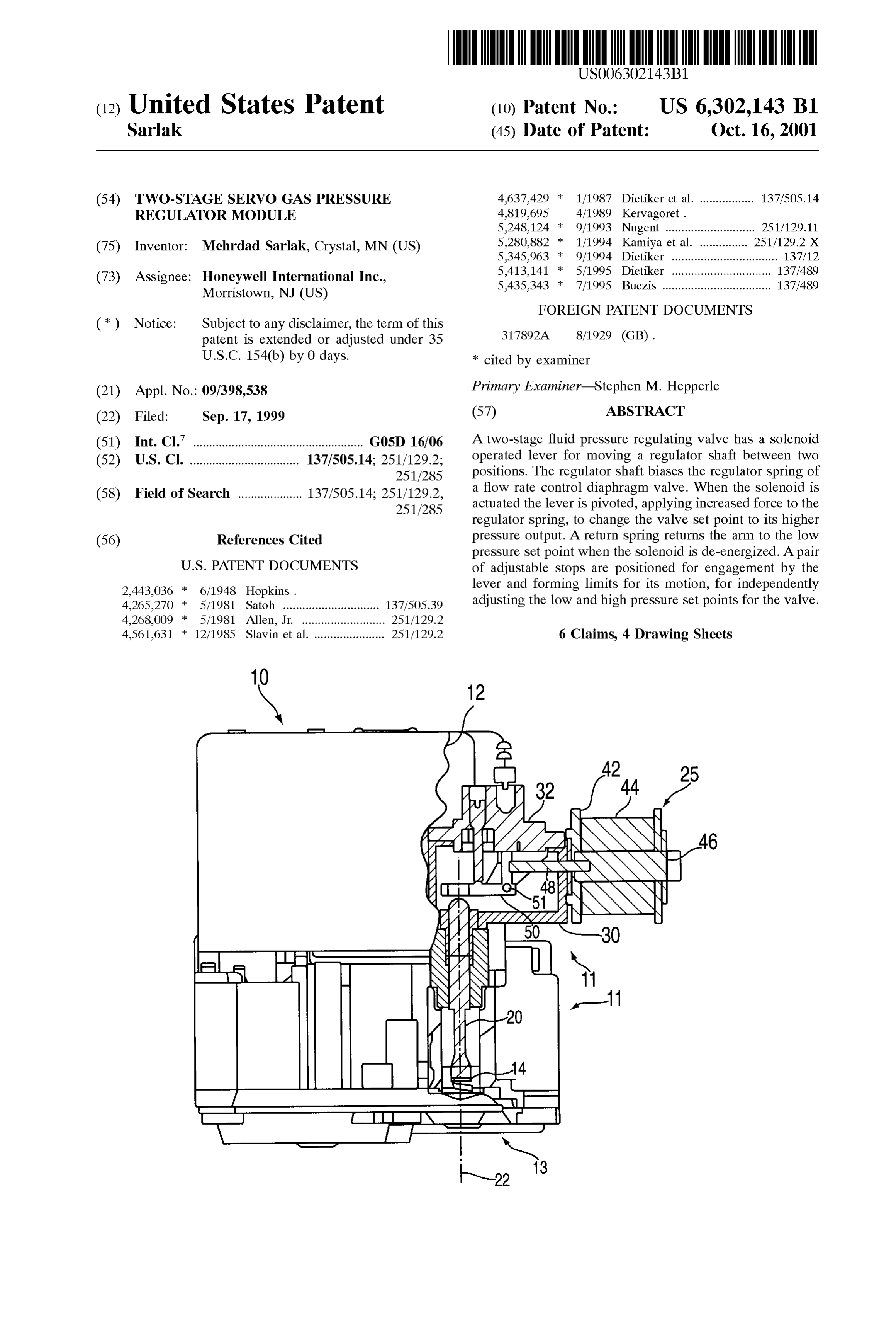
REFERENCE TO “MICROFICHEAPPENDIX BRIEF DESCRIPTION OF THE DRAWINGS Not Applicable. 15 FIG. 1 illustrates a pressure regulating valve according
BACKGROUND OF THE INVENTION
the applicants invention, with portions broken away to show construction of a two-stage regulator used therein;
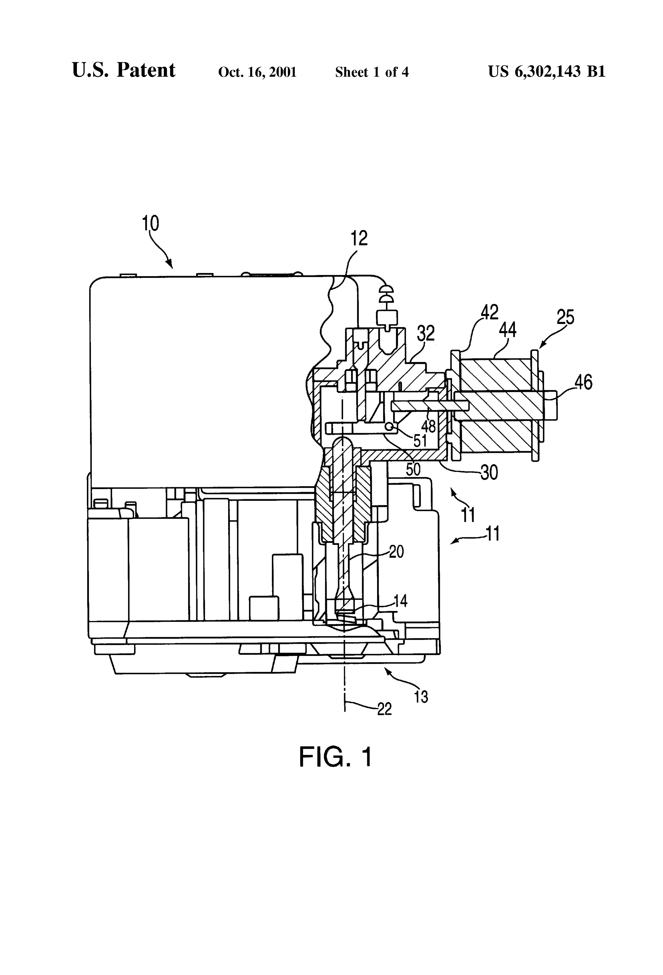
1. Field of the Invention FIG. 2 is an enlarged view of the linkage including a lever, This invention relates generally to fluid pressure regulat used in the valve of FIG. 1;
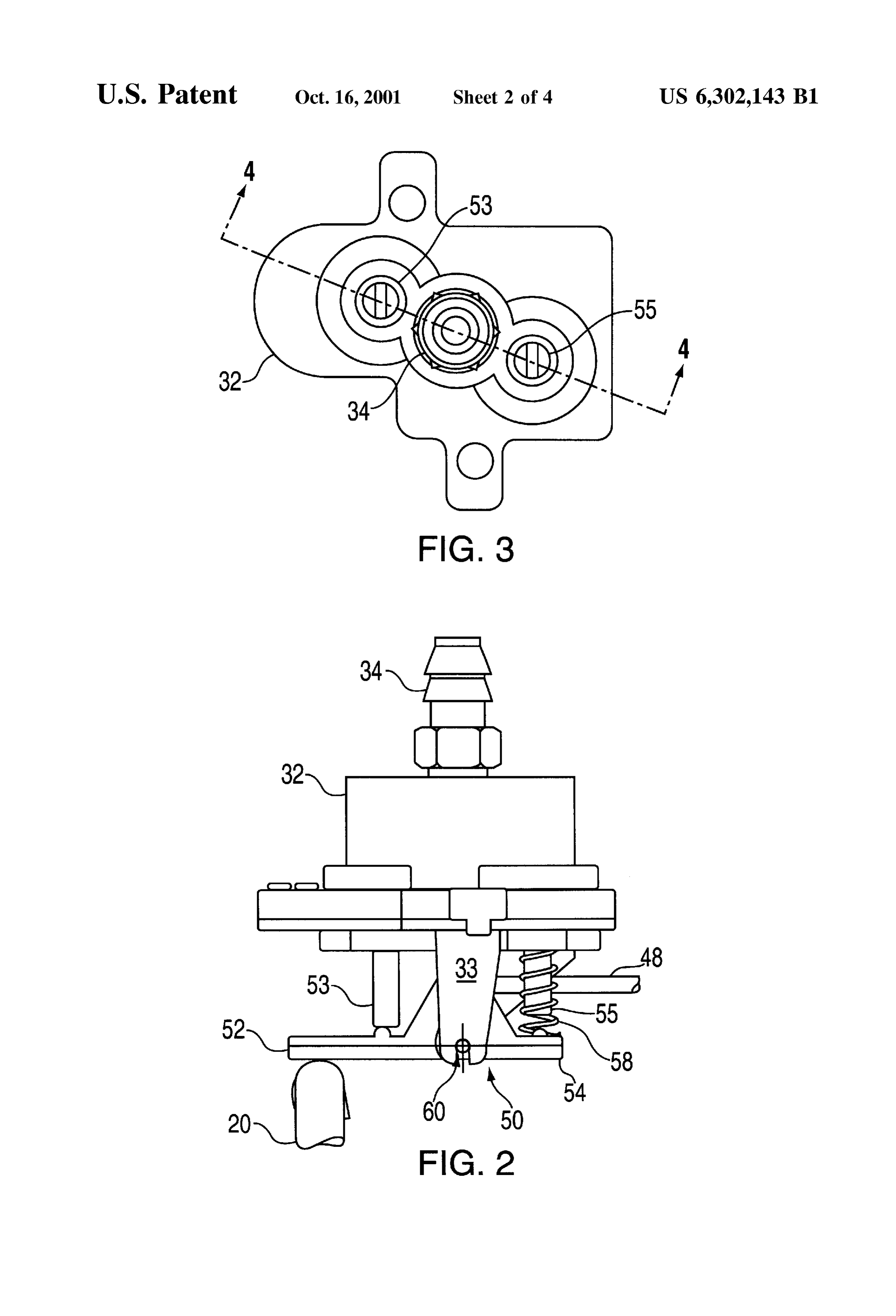
ing valves, and more specifically to two-stage Servo gas FIG. 3 is a top view of the servo regulator portion of the preSSure regulators convertible to Separate output pressure valve of FIG. 1;
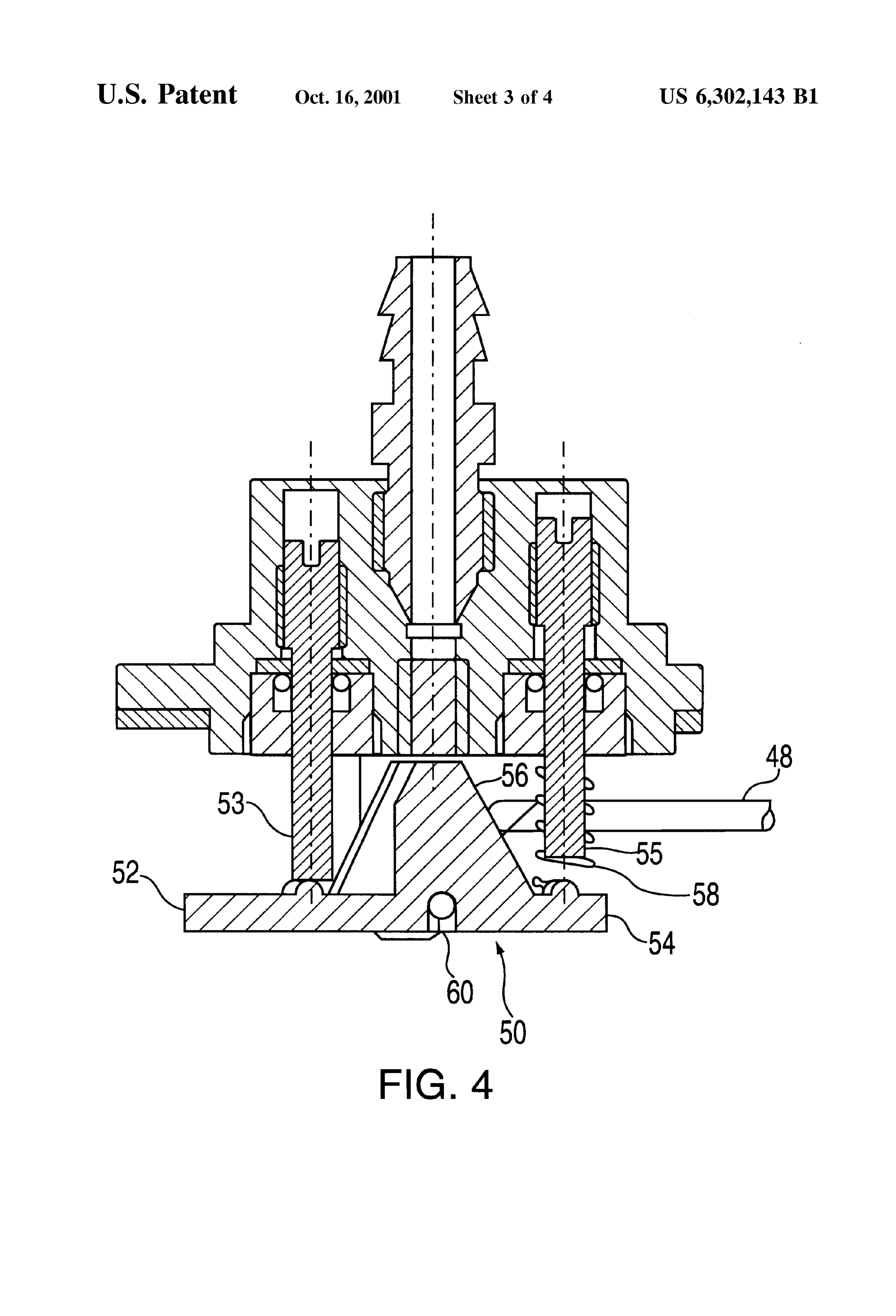
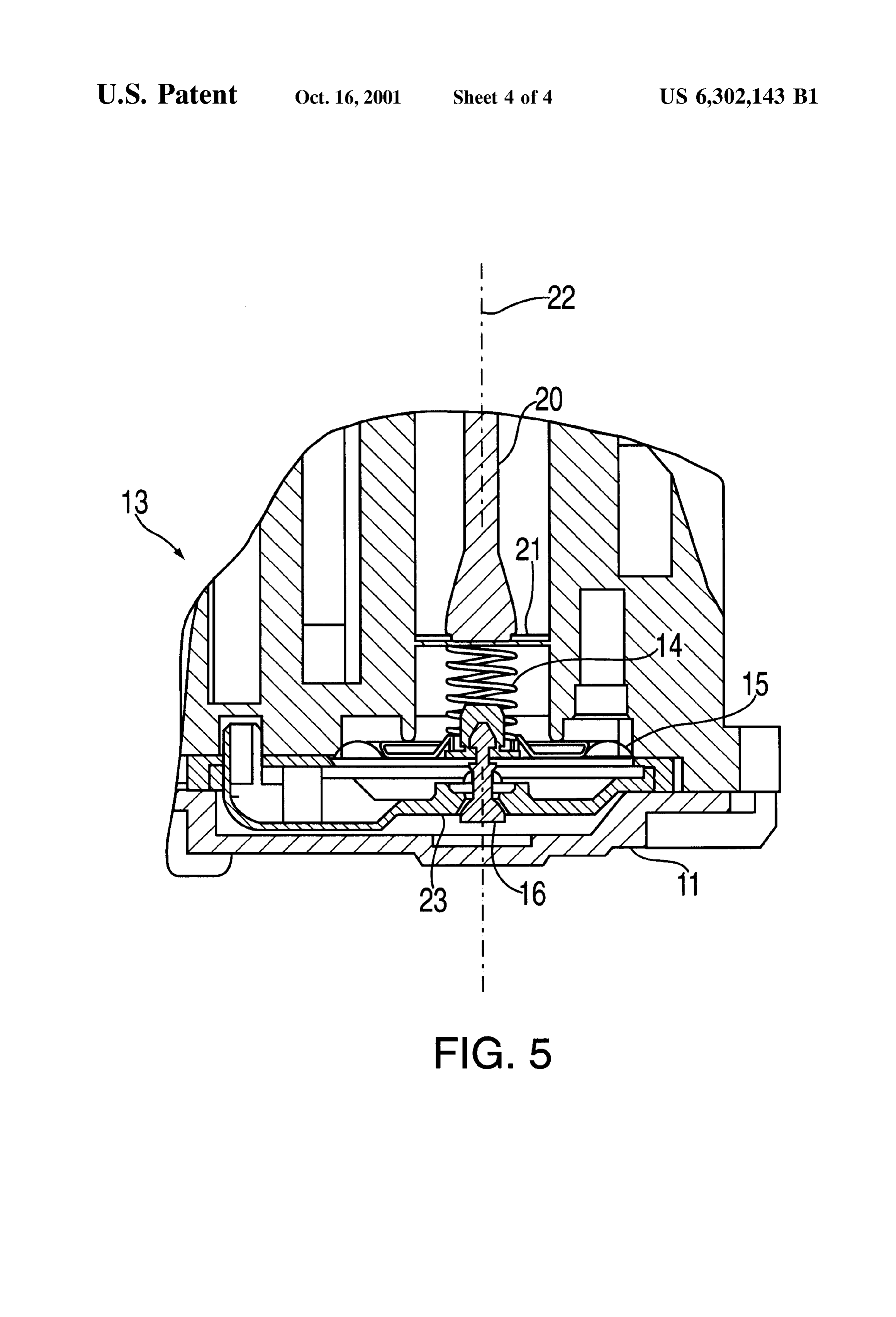
ranges, Such as those typically used in natural and LP fuel FIG. 4 is a sectional view taken along line 4-4 in FIG. gas controls. 3; and 2. Background of the Invention FIG. 5 is an enlarged sectional view of the servo valve Fluid pressure regulating valves are widely used in a 25 portion of the valve of FIG. 1.
number of applications. One important application is in the control of gas pressure in gas heating appliances. Typically DETAILED DESCRIPTION OF THE the heat output Such appliances is controlled by metering the INVENTION combustion gas through an orifice operating on a known and Referring to the FIG. 1, reference numeral 10 generally controlled preSSure drop. Because the Supply conditions for identifies a fluid pressure regulating valve having a portion the gas may vary, a pressure regulating valve is used to of its housing assembly 11 broken away along line 12 to achieve the known pressure drop, and therefore a known gas illustrate, in the right-hand Side of the Figure, components flow to the burner. Usually a spring reference is used for relevant to the two-stage module of the present invention. maintaining the constant pressure drop, and a Service adjust 35 Reference number 13 identifies a conventional diaphragm ment is provided for fine tuning the regulated pressure. Also, type servo valve (shown in greater detail in FIG. 5), which Single-stage valve designs are known which facilitate regulates the control preSSure for a main flow control valve replacement of the reference Spring to permit Valve conver according to the force of regulator Spring 14. AS shown in Sion for operation with different gases having different FIG. 5, one end of this spring bears against a diaphragm characteristics, for example, natural gas and LP gas. 40 assembly 15 which carries a servo valve closure member 16. Two-stage gas regulators are used to Switch the pressure The other end of regulator Spring 14 is Secured on a Spring regulation, and hence the burner heat output, between a low retainer 21 on one end of a shaft 20 slideable in housing preSSure and a higher pressure regulation point. This is often assembly 11 along an axis 22 toward and away from a Servo accomplished by a Solenoid energized by the heating System valve seat 23.
control. 45 AS is explained in greater detail hereinafter, Shaft 20 is Many types of regulating valves have been provided in part of a linkage through which the compression of regulator the prior art to accomplish these tasks. Some have used Spring 14 may be varied, in part by an actuator, Such as a multiple regulators in one housing, which can lead to Solenoid 25. When shaft 20 is permitted to move to its complex and expensive assembly. Others have used com upward limit (as seen in FIG. 1), Spring 14 applies a plex linkages for internal adjustments. Others have provided 50 minimum force to diaphragm assembly 15, corresponding to high and low adjustments which are interrelated, compli a low pressure set point. When shaft 20 is moved to its cating the adjustment process. However, no known two downward limit, Spring 14 is compressed, resulting in appli Stage valve designs readily permit reference Spring replace cation of a higher force to diaphragm 15, corresponding to ment to provide for simple conversion for operation with a high pressure Set point.
different gases. 55 The two-stage regulator module includes Separable hous
BRIEF SUMMARY OF THE INVENTION
ing portions, including a main housing 30 and a cover 32.
Main housing 30 may be attached to the remainder of
The present invention is a preSSure regulating valve with housing assembly 11 by Screws or other fastening devices two-stage operation and independent adjustability of low (not shown), and may be designed to replace the cover of an and high regulated preSSures. According to the present 60 existing Single-stage valve of the general type of Valve 10, invention there is provided a regulating valve having a valve So that it can be field-converted to two-stage operation. housing defining a valve Seat and a flow rate control dia The actuation force for moving shaft 20 to the high phragm mounted in the housing proximate the valve Seat for preSSure Set point position is provided by Solenoid 25 or controlling flow therethrough as a function of extension of other actuator. Solenoid 25 includes a two part frame 42, of a regulator Spring located between the diaphragm and a 65 which one part is attached to the side of main housing 30. Spring retainer. Position of the retainer relative to the valve Solenoid 25 also has an excitation coil 44, which is con Seat is controlled in part by an actuator through a linkage nected to a Switchable Source of electrical power, through a
Page 7
heating control system (not shown). Solenoid 25 includes from the exterior of valve 10, without requiring disassembly. armature or plunger 46 having an extension 48 which Further, adjustments of the low and high preSSure Settings projects into housing 30 to engage a lever 50 mounted for are entirely independent of one another. Thus, adjustment of pivotal movement about an axis 51 transverse to axis 22. the Settings can be made in any order, and one Setting can be As seen in best in FIGS. 2 and 4, lever 50 is of a generally adjusted without necessitating readjustment of the other T-shaped configuration, and has arms 52 and 54 extending in Setting.
opposite directions from axis 51, and a leg 56 extending A further advantage of the above-described design is that from axis 51 perpendicular to arms 52 and 54. Note that it facilitates conversion of the valve from Settings appropri lever 50 appears L-shaped in FIG. 1 because the section is ate for one fuel to Settings appropriate for a different fuel. taken through the center of Solenoid 25 which is offset along This conversion generally requires replacement of regulator axis 51 from arm 54. Spring 14. Such replacement is easily accomplished by Lever 50 is pivotally attached by a pin 60 between a pair removal of cover 32, which also results in removal of lever of support projections 33 formed on the underside of cover 50. This provides access to shaft 20 which may be removed 32. Adjustable stops, in the form of screws 53 and 55, are 15 with regulator Spring 14 by pulling the Shaft out along acceSS provided to limit pivotal movement of lever 50. As seen in 22. Spring 14 may then be replaced with a Spring having a FIG. 3, screws 53 and 55 are positioned at an angle to the different Spring constant which will produce output pres axis of Solenoid 25, and for that reason Screw 55 does not Sures appropriate for the desired type of fuel. The regulator appear in FIG. 1, but does appear in FIGS. 2 and 4, where portion of the valve is then easily reassembled with the new extension 48 of Solenoid armature 46 appears behind screw regulator Spring.
55. Although a specific embodiment of a diaphragm valve Screw 53, which controls the low pressure setting, is with the applicant's unique two-stage Servo regulator mod received in a threaded aperture in cover 32 so that screw 53 ule has been shown and described for illustrative purposes, may be adjusted from the exterior of the cover to determine a number of variations and modifications within the appli the point of contact of arm 52 with the screw. Likewise, 25 cant's contemplation and teaching will be apparent to those Screw 55, which controls the high pressure Setting, is skilled in the relevant arts. The invention for which protec received in a threaded aperture in cover 32, so that screw 55 tion is sought is not to be limited by the disclosed may also be adjusted from the exterior of the cover to embodiment, but only by the terms of the following claims. determine the point of contact of arm 54 with the screw. The embodiments of an invention in which an exclusive Reference numeral 34 identifies a vent fitting in cover 32. property or right is claimed are outlined as follows: The underside of arm 52 bears on the top end of regulator 1. In a pressure regulating valve of the type including a shaft 20. Extension 48 of the Solenoid armature, when housing assembly defining a Servo regulator valve Seat and actuated, pushes against leg 56 of lever 50. A spring 58, containing a closure member moveable along a first axis shown captured on screw 55, biases lever 50 in a clockwise toward and away from the Servo regulator valve seat by direction, as seen in FIGS. 2 and 4. This serves as a return 35 means of a diaphragm responsive to force exerted by a Spring for Solenoid armature 46, although it will be appre regulator Spring between the diaphragm and a Spring retainer ciated that the return Spring function could be provided whose position along the first axis is determined in part by equally well with a variety of different Spring configurations an actuator, the improvement which comprises: and/or locations. a lever mounted for pivotal movement about a Second axis In operation, when solenoid 25 is unenergized, lever 50 is 40 transverse to the first axis, the Spring retainer being rotated to its clockwise (as seen in FIGS. 1, 2 and 4) limit coupled to Said lever at a first location Separated from by the action of return Spring 58. Regulator Spring 14, the Second axis, whereby the regulator Spring biases through regulator shaft 20, also tends to rotate lever 50 in a Said lever to rotate about the Second axis in a first clockwise direction. However, it is considered preferable to direction; the actuator being coupled to Said lever and include a separate return Spring, rather than to rely on the 45 operable, when energized, to rotate Said lever about the regulator Spring alone to return the Solenoid armature . The Second axis in a Second direction opposite the first clockwise limiting position is Set by contact of arm 52 with direction;
screw 53. In this position, as shown in FIGS. 1, 2 and 4, a first stop positioned to limit rotation of Said lever in the valve 10 is set for its low pressure output. Specifically, the first direction;
position of shaft 20 is determined by the setting of screw 53, 50 a Second Stop positioned to limit rotation of Said lever in which, in turn, determines the low pressure Set point of the the Second direction;
valve.
Said lever is of a configuration having first and Second
When Solenoid 25 is energized, extension 48 causes lever portions projecting in Separate directions from the 50 to rotate in a counter clockwise direction until arm 54
Second axis, contacts screw 55. This counter clockwise motion pushes 55 the Spring retainer is coupled to Said lever at a location on shaft 20 downward, and increases the force of regulator the first portion of the lever: and spring 14 on diaphragm 15. In this state valve 10 is set for its high pressure output. Specifically, the position of Shaft 20 the actuator is a Solenoid assembly coupled to Said lever is determined by the setting of set screw 55, which, in turn, at a location on the Second portion of the lever. determines the high pressure Set point of the valve. 60 2. The pressure regulating valve of claim 1 wherein: It should be noted that although a solenoid is shown and Said lever is of a configuration having a third portion described for causing lever 50 to pivot, other types of projecting from the Second axis in a direction Separate actuators could be used to perform the same function. For from the directions the first and Second positions example, lever 50 could be driven by a rotary actuator project from the Second axis, and extending along axis 51. 65 Said first and Second stops are positioned to contact Said One advantage of the applicant's design is that adjustment lever at locations on the first and third portions of the of the low and high preSSure output Settings can be made lever respectively.
Page 8
S 6 3. The pressure regulating valve of claim 2 further includ coupled to Said lever at a first location Separated from ing a return Spring between Said lever and the housing the Second axis, whereby the regulator Spring biases assembly positioned to bias Said lever to rotate in the first Said lever to rotate about the Second axis in a first direction. direction, the actuator being coupled to Said lever and 4. The pressure regulating valve of claim 3 wherein: operable, when energized, to rotate Said lever about the Said lever is of a generally T-shaped configuration having Second axis in a Second direction opposite the first first and Second arms extending in opposite directions direction;
from the Second axis, each of the first and Second arms a first stop positioned to limit rotation of Said lever in the having first and Second Sides generally parallel with the first direction;
Second axis, Said lever further having a leg extending from the Second axis in a direction generally perpen a Second Stop positioned to limit rotation of Said lever in dicular to the first and Second arms, the Second direction;
the Spring retainer is coupled to Said lever at a location on the housing assembly includes first and Second Separable the first side of the first arm thereof; housing portions, the first housing portion defining the 15 Servo regulator valve Seat, and having the diaphragm the actuator is coupled to Said lever at a location on the leg thereof; mounted thereto, the Second housing portion having the first Stop is adjustably mounted in the housing Said lever pivotally mounted thereon; assembly, and positioned to contact the Second Side of the Spring retainer is carried on a shaft slideable within the first arm of said lever; and Said first housing portion along the first axis toward and Said Second Stop is adjustably mounted in the housing away from the Servo regulator valve Seat, and assembly and positioned to contact the Second arm of with the regulator Spring, is removable from Said first Said lever. housing portion when Said first and Second housing 5. In a pressure regulating valve of the type including a portions are separated, whereby regulator Springs of housing assembly defining a servo regulator valve Seat and 25 different spring constants can be installed to provide containing a closure member moveable along a first axis different regulated pressures. toward and away from the Servo regulator valve Seat by 6. The pressure regulating valve of claim 5 wherein the means of a diaphragm responsive to force exerted by a Solenoid includes an armature, and is mounted on the regulator Spring between the diaphragm and a Spring retainer housing assembly So that the armature is moveable in a whose position along the first axis is determined in part by direction transverse to the direction of movement of the an actuator, the improvement which comprises: shaft in Said first housing portion.
a lever mounted for pivotal movement about a Second axis transverse to the first axis, the Spring retainer being
Provenance
- Collection
- Cited prior art
- Original PDF
- patentimages.storage.googleapis.com →
- Filed
- 1999-09-17
- Pages
- 8
- Method
- pdftotext (the PDF's own text layer) + pdftoppm 300dpi page scans
- Source
- Google Patents bibliographic record
- Granted
- 2001-10-16
- Inventors
- Mehrdad Sarlak; Honeywell International Inc
- Transcribed from
- patentimages.storage.googleapis.com →