patent · US6267585
Method and combustor for combusting hydrogen
31 July 2001
Page 1 — bibliographic record
(12) United States Patent (10) Patent No.: US 6,267,585 B1 Suttrop (45) Date of Patent: Jul. 31, 2001
(54) METHOD AND COMBUSTOR FOR FOREIGN PATENT DOCUMENTS
COMBUSTING HYDROGEN
3902026 7/1989 (DE) ..................................... 431/354 (75) Inventor: Friedemann Suttrop, Aachen (DE) 580500 * 1/1994 (EP).
(73) Assignee: DaimlerChrysler Aerospace Airbus 2250339 * 6/1992 (GB). GmbH, Hamburg (DE) OTHER PUBLICATIONS
John B. Heywood et al. Parameters Controlling Nitric Oxide (*) Notice: Subject to any disclaimer, the term of this Emissions from Gas Turbine Combustors, AGAR patent is extended or adjusted under 35 D-CP-125, Neuilly Sur Seine, France, Apr. 1973, pp. 21-1 U.S.C. 154(b) by 0 days. to 21-16.
Ziemann et al. Low-NO Combustors for Hydrogen Fulled (21) Appl. No.: 09/307,125 Aero Engine, World Hydrogen Energy Conference, Stut tgart, Germany, Jun. 1996.
(22) Filed: May 7, 1999 V.A. Sosounov et al. Experimental Turbofan using Liquid Hydrogen and Liquid Natural Gas as Fuel, Joint Propulsion
Related U.S. Application Data Conference, Orlando, FL. USA, Jul. 1990, pp. 1 to 11. F. Shum et al; Potential Use of Hydrogen in Air Propulsion;
(63) Continuation-in-part of application No. 08/769,785, filed on Final Report; Dec., 1996; pp. 101, 102, 104, 106, 109. Dec. 18, 1996, now abandoned.
* cited by examiner (51) Int. Cl. ............................. F23D 14/12; F23D 14/10 (52) U.S. Cl. .............................. 431/354; 431/8; 431/278; Primary Examiner-Carl D. Price 431/285; 431/10; 431/328; 239/420; 239/424.5; (74) Attorney, Agent, or Firm W. F. Fasse; W. G. Fasse 239/433: 239/434; 239/426 (57) ABSTRACT (58) Field of Search ..................................... 431/278, 354, A plate burner for combusting hydrogen with air as an 431/10, 8, 285,326, 328; 126/39 E; 239/420, oxidizer forms a wall portion of a combustion chamber for 421, 424, 424.5, 426, 432, 433, 434, 568, example of a gas turbine. The plate burner is So constructed 562; 60/737, 739 that air and hydrogen are Separately guided to the down stream Surface area facing into the combustion chamber for (56) References Cited forming a large number of diffusive microcombustion
flames, thus achieving a very low mixing Scale Simulta neously with a high nixing intensity. The number of diffu 231,013 8/1880 Crutchett. sive micorcombustion flames is so selected that the NO 1539,093 5/1925 Mettler. content in the exhaust gas from the combustion chamber is 1971,208 8/1934 Butz et al. . at the most 10x10 cubic foot per cubic foot of exhaust gas. 2,497,476 2/1950 Stadler. The hydrogen enters the entrance area into the combustion 2,601.242 6/1952 Bonvillian et al. .................. 431/115 chamber either through a porous wall, and air is injected into 3,181,590 5/1965 Dupler. the hydrogen environment to form inverse diffusive micro 3,504,994 4/1970 Desty et al. . combustion flames or the hydrogen is injected through a 3,617.224 11/1971 Brun-Tsekhovol. multitude of fine holes into high Velocity air jets forming 3,724.994 * 4/1973 Desty. regular diffusion flames. In both instances, the formation of 3,870,459 3/1975 Desty et al. . NO in the exhaust gas during combustion is reduced to the 4,100,733 7/1978 Striebel et al. . above level or below.
4,845,952 7/1989 Beebe ..................................... 60/737 4,887.963 * 12/1989 Lemer. 8 Claims, 6 Drawing Sheets

Page 2
Drawing sheet — no readable text.
Page 3
Drawing sheet — no readable text.
Page 4
Drawing sheet — no readable text.
Page 5
Drawing sheet — no readable text.
Page 6
Drawing sheet — no readable text.
Page 7
Drawing sheet — no readable text.
Page 8
METHOD AND COMBUSTOR FOR plate configuration is inserted into the combustion chamber, COMBUSTING HYDROGEN whereby the hydrogen flows in a direction croSSwise to an air flow direction. The air flow direction is referred to herein
CROSS-REFERENCE TO RELATED as the main or primary flow direction, while the hydrogen APPLICATION flow direction is referred to as the secondary flow direction. The hydrogen distribution chamber includes a multitude of
This is a Continuation-In-Part application of my parent air guide tubes extending in the main flow direction as copending application U.S. Ser. No. 08/769,785; filed on shown by Striebel et al. Each tube has an inlet and an outlet Dec. 18, 1996, now abandoned. The priority of the parent opening for the air. Each air guide tube communicates case is claimed under 35 U.S.C. S 120. The German priority through small bores or holes with the hydrogen distribution date of Dec. 19, 1995 is claimed through the parent appli chamber. These bores or holes are positioned close to the cation under 35 U.S.C. S 119. inlet opening of the respective tube So that premixing can
FIELD OF THE INVENTION
take place in each tube. If hydrogen is introduced into the hydrogen distribution chamber, it flows in the Secondary
The invention relates to a method and burner or combus 15 flow direction crosswise to the primary flow direction tor for combusting hydrogen by diffusion combustion using toward the individual bores or holes in the tubes and thus can air as an oxidizer. This method and combustor are especially enter into the air guide tubes which function as premixing useful in connection with gas turbine combustion chambers tubes. AS air is passed through these air guide tubes hydro in aircraft engines. gen and air are mixed with each other within the air guide tubes before entry of the air fuel mixture into the combustion
BACKGROUND INFORMATION chamber. Such an arrangement of the hydrogen distribution chamber provides a Substantially simplified Structural con
The use of hydrogen (H) as fuel for burners of all kinds, figuration of the burner because individual ducts for the for example for combustors in combustion chambers of gas hydrogen to the individual air guide tubes or to the indi turbines, has the advantage of an especially high reactivity 25 vidual combustion Zones are not needed. and thus an extraordinary large Stability in the combustion. A Second group of hydrogen combustors that works This Stable combustion is achieved even if there is an exceSS without remixing of air and hydrogen recognizes the impor air Supply as is the case in the combustion chambers of gas tance of the mixing degree for reducing the generation of turbines.
NO in the combustion of hydrogen. This second group of
Publications relating to combustion techniques by Hey combustors uses diffusion combustion for which an wood and Mikus show that a reduction in the formation of increased number of hydrogen injection nozzles are nitrogen oxides (NO) can be achieved in combustion flames required. Such nozzles are normally conventional Vortex with a Sufficiently high air exceSS if the mixing quality of air twist generating nozzles. Reference is made in this connec and fuel is increased. According to Heywood and Mikus, the tion to TRUD by Kusnetzov, published in Russia, and to NO formation can be minimized by a completely homoge 35 publications by Motoren-Und Turbinen-Union (MTU) of neous fuel-air mixture as can be attained, for example, by Munich, Germany. The Kusnetzov principle published in premixing of the fuel and air upstream of the combustion TRUD for example permits increasing the total number of flame proper as viewed in the gas flow direction. A respec combustion flames over the available burner surface area by tive Suggestion of a homogeneous premixing of the fuel and a factor of 5 or larger compared to other conventional air Supply with hydrogen as fuel, has been made by Pratt and 40 hydrogen burners. Thus, a combustion chamber convention Whitney of Canada. In spite of the advantages that are ally with a given number of combustion flames, for example attained by the premixing with regard to the reduction of 30 Such flames, can be modified to have 150 or more flames nitrogen oxides emissions in engine exhaust gases, there is over the entire available burner Surface area facing into the a Substantial drawback in Such premixing in that flame combustion chamber. Each of these individual combustion flashbacks from the combustion chamber back into the 45 flames still has a diameter of about 20 mm. The TRUD or premixing area can happen. Such flame flashbacks are very KuSnetzov System has its limitations in further increasing dangerous. the number of hydrogen injection nozzles, because the U.S. Pat. No. 4,100,733 (Striebel et al.) discloses a premix increased number of combustion Zones also requires increas combustor with elaborate efforts to reduce “noxious con ing the number of individual hydrogen Supply pipelines. taminants' from engine exhaust gases. More specifically, a 50 U.S. Pat. No. 3,504,994 (Desty et al.) and U.S. Pat. No. stable operation without flame flashbacks and the reduction 3,870,459 (Desty et al.) disclose fluid fuel burners falling of NO are the goals of Striebel et al. This aim is achieved into the Second group of burners using diffusion mixing. The according to Striebel et al. by a plurality of primary tubes air is Supplied through a plurality of tubes which offer a low wherein fuel and air are premixed at low fuel flow rates and resistance to air flow making the Desty et al. System par a plurality of Secondary tubes for further mixing once a 55 ticularly suitable for use with natural draught. The fluid fuel threshold fuel flow rate has been reached. Such stepwise is Supplied through the gaps between the air Supply tubes or premixing achieves a reasonably homogeneous fuel air through a layer of metal Sponge positioned in the gaps mixture prior to entry into the combustion chamber and between the tubes. Temperature variations cause expansions presumably flashbacks are avoided as long as low BTU fuels and contractions of the air tubes, whereby the flow croSS are used as is emphasized by Striebel et al. A Substantial risk 60 Sectional dimensions of the gaps between the air tubes are of flashbacks, however, cannot be avoided by the teachings not dimensionally Stable. Hence, the fuel Supply is not stable of Striebel et al. if the fuel is hydrogen having very large either.
flame Velocities. There is room for improvement, especially with regard to The above discussed first group of conventional burners the reduction of NO in diffusion burners. The disclosure of or combustors which uses premixing of hydrogen and air 65 U.S. Pat. No. 3,504,994 (Desty et al.) tries to improve the generally requires burners of relatively simple construction. fuel air mixing by a baffle plate that has holes Surrounding For example, a hydrogen distribution chamber having a the outlet ends of the air supply tubes, whereby fuel flow
Page 9
ring gaps are formed that Surround the air outlet ends of the combustion chamber, So that Said first and Second direc tubes directly below the baffle plate. While the baffle plate tion enclose a mixing angle; may improve the mixing it will not necessarily improve the (c) diffusively micromixing said hydrogen and air with each Steadiness of the fuel Supply. Similar considerations apply to other in Said combustion chamber to avoid premixing an end plate with fuel exit holes which direct the fuel jets in outside Said combustion chamber, for generating a num parallel to the air jets, thereby neither improving the mixing ber of stable distinct diffusive microcombustion flames; nor the NO reduction. (d) Sustaining said micromixing in each of Said diffusive
OBJECTS OF THE INVENTION
microcombustion flames in Said combustion chamber by a turbulence intensity that depends on a pressure drop
In view of the above it is the aim of the invention to available in Said combustion chamber for maintaining achieve the following objects Singly or in combination: each of Said diffusive microcombustion flames distinct to provide a method for a micromix diffusive combustion from any other of Said flames, and of hydrogen that can be practiced by generating a (e) selecting said mixing angle and Said number of distinct multitude of diffusive microcombustion flames formed 15 and Stable diffusive microcombustion flames per Square inch of Said burner Surface area So that the formation of in a burner for reducing the generation of NO in engine said nitrogen oxides NO in Said exhaust gas is at a level exhaust gas by at least 80% to low levels of 20% or less of 10x10 cubic foot of NO per cubic foot of said of conventional NO levels in burners of comparable exhaust gases at the most during combustion as measured Size; at atmospheric burner entrance conditions. to achieve a reduction in the formation of NO to levels A combustor according to the invention combines the at or below 10x10 cubic foot of NOx per cubic foot following features: a combustion chamber in which exhaust of exhaust gas produced by an engine operating with gas including nitrogen oxides NO is produced during the present diffusive burner that avoids premising; combustion, Said combustor comprising a burner Surface to avoid the need for a large number of hydrogen Supply area facing into said combustion chamber (CC), a number of pipes or ducts by feeding hydrogen to a multitude of 25 hydrogen fuel inlet through-holes in Said combustor for diffusive microcombustion flames through one or only feeding hydrogen jets into Said combustion chamber, a a few hydrogen Supply ducts, plurality of air inlets in Said combustor for feeding air jets to utilize the cooling capacity of the hydrogen to cool the into Said combustion chamber, Said fuel inlet through-holes combustion and combustion chamber; and Said air inlets being So positioned relative to each other to miniaturize the diffusive combustion flames so that and relative to said combustion chamber that a flow direc they are at least ten-fold Smaller than conventional tion of Said hydrogen jets and a flow direction of Said air jets diffusive combustion flames in diffusion burners So that enclose a mixing angle for diffusive micromixing of hydro several thousand individual and distinct diffusion gen and air in Said combustion chamber with a mixing microcombustion flames may be formed in a combus 35 intensity that depends on a pressure drop available in Said tion chamber; combustion chamber for Sustaining a number of distinct and to cause an intensive air-hydrogen diffusive micromixing Stable diffusive microcombustion flames per Square inch of Said burner Surface area, Said number of flames in combi in a multitude of diffusive microcombustion flames nation with Said mixing angle maintaining Said nitrogen without any premixing to thereby achieve a Substantial oxides NO at most at a level of 10x10 cubic foot of NO. reduction of the nitrogen oxide formation and emission while Simultaneously achieving the advantage of 40 per cubic foot of Said exhaust gases during combustion as avoiding flame flashbacks due to the use of diffusive premixing atoutside measured atmospheric burner entrance conditions and
Said combustion chamber is avoided.
combustors, The invention selects a sufficiently large number of dif to optimally increase the mixing intensity while minimiz fusive microcombustion flames and takes advantage of the ing the mixing Scale by efficiently using as much as 45 preSSure drop in the combustion chamber for achieving a possible the pressure drop or pressure loSS energy in a Small mixing Scale in combination with a maximized or at turbine combustor for enhancing the diffusive fuel air least optimized mixing intensity as is explained in more mixing by eddy transport in a multitude of diffusive detail below. Premixing is avoided according to the inven microcombustion flames, and tion whereby flashback is prevented with certainty. to rapidly disperse in the present combustor any Stoichio 50 The miniaturization of the diffusive microcombustion metric high temperature spots or Zones that tend to flames and the increase of the number of Such flames per form in connection with diffusion flames and that are Square inch of burner Surface area as taught by the invention primarily responsible for gas phase NOX-production. achieves an advantageously Small mixing Scale Simulta
SUMMARY OF THE INVENTION
neously with an increased mixing intensity. The term “mix 55 ing Scale” as used herein corresponds to the “scale of
The above objects have been achieved by the present turbulence” used in connection with turbulent flows. A large method and by the present combustor. More specifically, the mixing Scale defines, for instance, rough non-uniformities of present method for combusting hydrogen as fuel and air as concentrations of mixing species which need long times to an oxidizer in a combustor including fuel inlets and air inlets be homogenized in the dissipation process of the available for diffusion combustion of Said hydrogen and air in a 60 turbulence energy. Therefore, an a priori Small Scale fuel combustion chamber having a burner Surface area wherein distribution combined with high energetic intensity of micro exhaust gas containing nitrogen oxides NO is produced turbulent eddies is best for the purposes of the invention. The during combustion, is performed by the following Steps: Small Scale fuel distribution is, according to the invention, (a) feeding air jets in a first direction through said air inlets achieved by choosing a Sufficiently large number of micro into Said combustion chamber; 65 combustion flames, whereas the high energetic intensity of (b) feeding Simultaneously hydrogen jets in a second direc turbulence is gained by making best use of the available tion through said hydrogen inlet through-holes into Said combustion chamber pressure drop, when the pressure loSS
Page 10
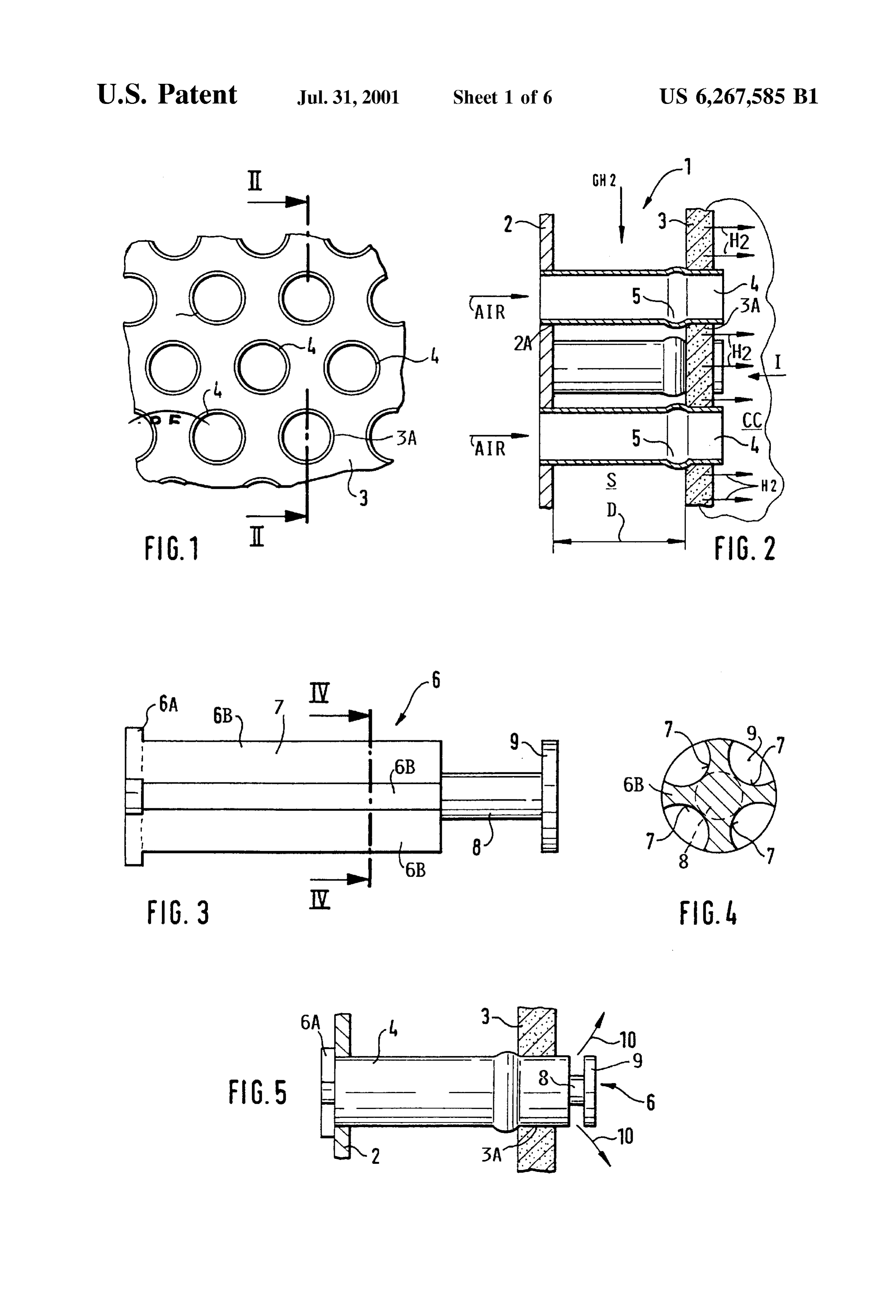
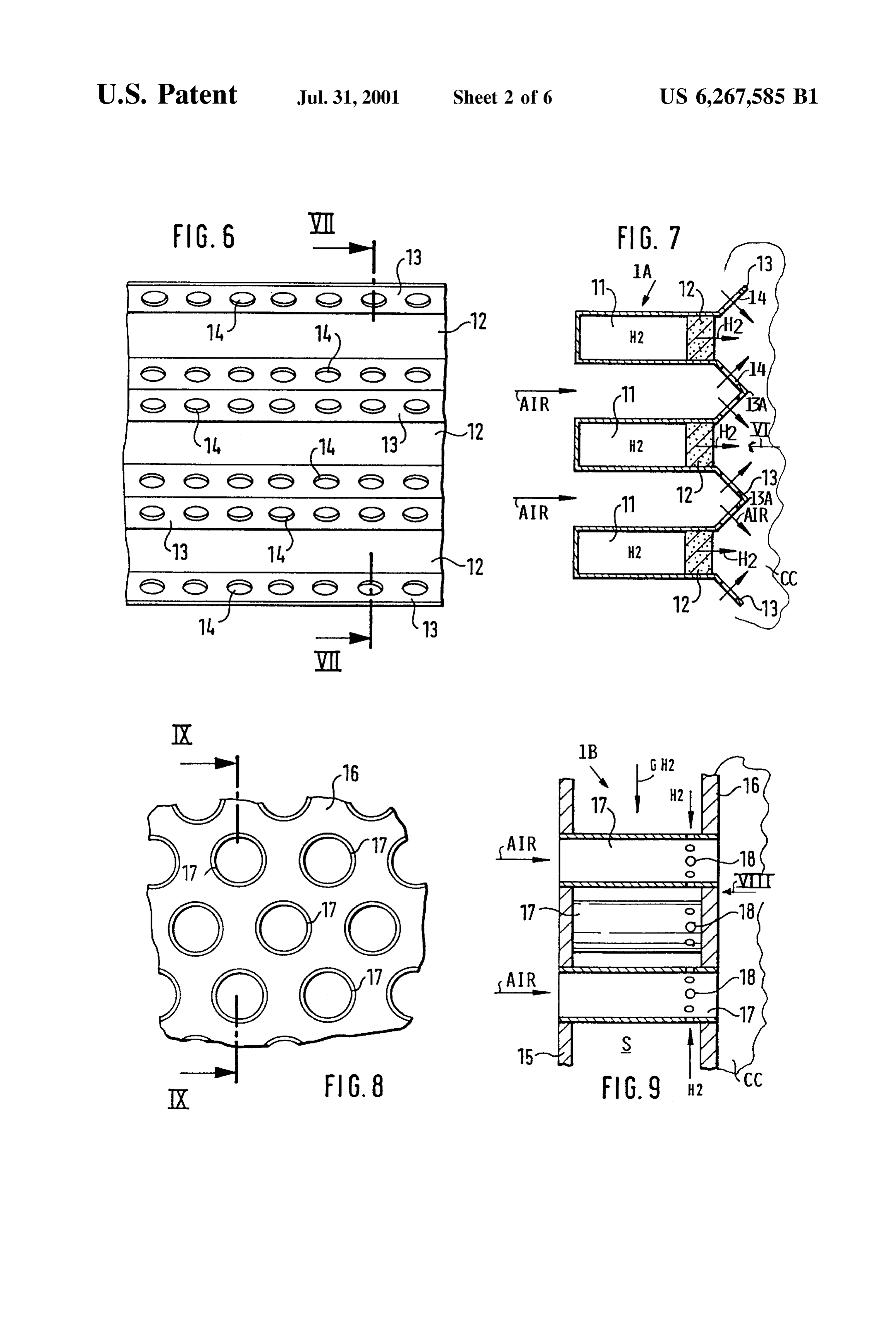
S 6 energy is utilized for accelerating the air or the fuel into the FIG. 7 is a sectional view along section line VII-VII in diffusive microcombustion flames. More specifically, the FIG. 6;
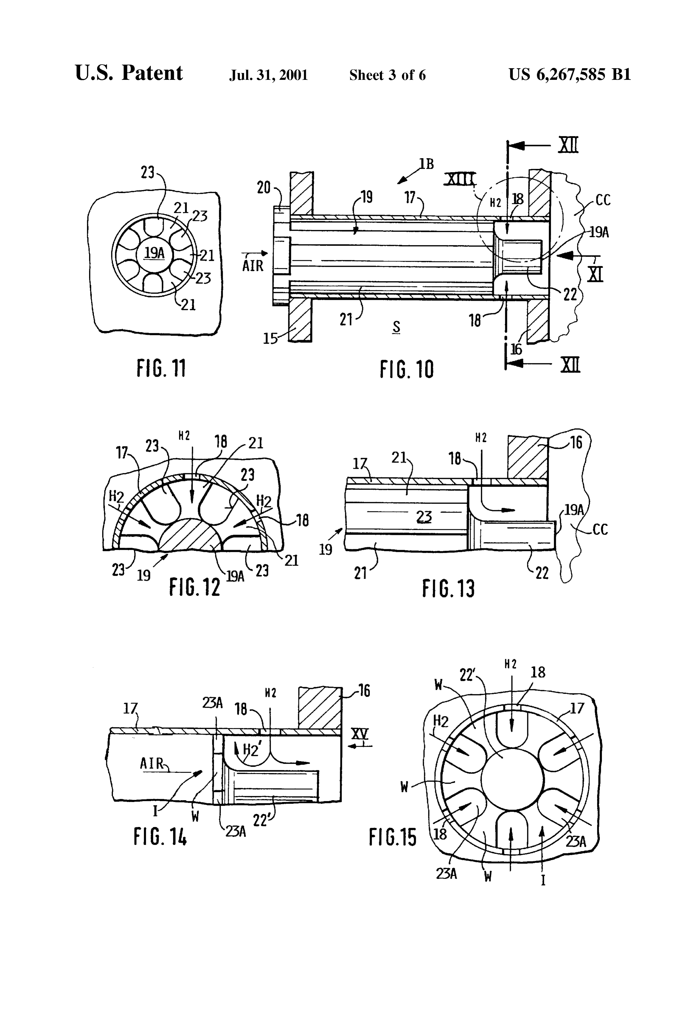
high kinetic energy of the air or fuel jets converts to FIG. 8 is a view similar to that of FIG. 1, but showing a turbulence energy as the air jets or fuel jets resolve into view in the direction of the arrow VIII in FIG. 9; turbulence. A Strong turbulence in turn accelerates the mix FIG. 9 is a sectional view along section line IX-IX in ing intensity by eddy transport. A rapid micromixing and homogenization of the air fuel mixture in the diffusive FIG. 8 illustrating hydrogen distribution holes at the exit end microcombustion flames makes Sure that Stoichiometric of air distribution tubes;
high temperature Zones are rapidly dispersed before they can FIG. 10 is a side view partially in section, illustrating an become harmful. Such Stoichiometric high temperature air guide pin inserted into a tube with hydrogen distribution Zones are unavoidable in diffusion flames but have been holes as shown in FIG. 9;
effectively rendered harmless by the invention. The rapid FIG. 11 is a view in the direction of the arrow XI in FIG. dispersion of the high temperature Zones is important 10;
because it reduces the formation of NO which tends to be FIG. 12 is a sectional view along section line XII-XII in formed primarily in these high temperature Zones where 15 FIG. 10, this time after a 30-degree angular rotation of the oxygen and nitrogen combine. Thus, the reduction of the air guide pin;
mixing Scale in combination with an optimally increased FIG. 13 shows the detail XIII in FIG. 10 on an enlarged mixing intensity are important features of the invention Scale, here again the air guide pin is rotated by 30 degrees, because a Small mixing Scale in combination with a large as in FIG. 12;
mixing intensity assure the reduction of NO to levels not attainable heretofore in the exhaust gases of gas turbine FIG. 14 is a view similar to that of FIG. 13, however engines, particularly aircraft engines which are operated by showing an air distribution flat insert instead of an air guide combusting hydrogen. The term “mixing intensity', as pin, furthermore, the insert is shown axially displaced rela Stated above, defines the rate of homogenization of the tive to the pin position of FIG. 13;
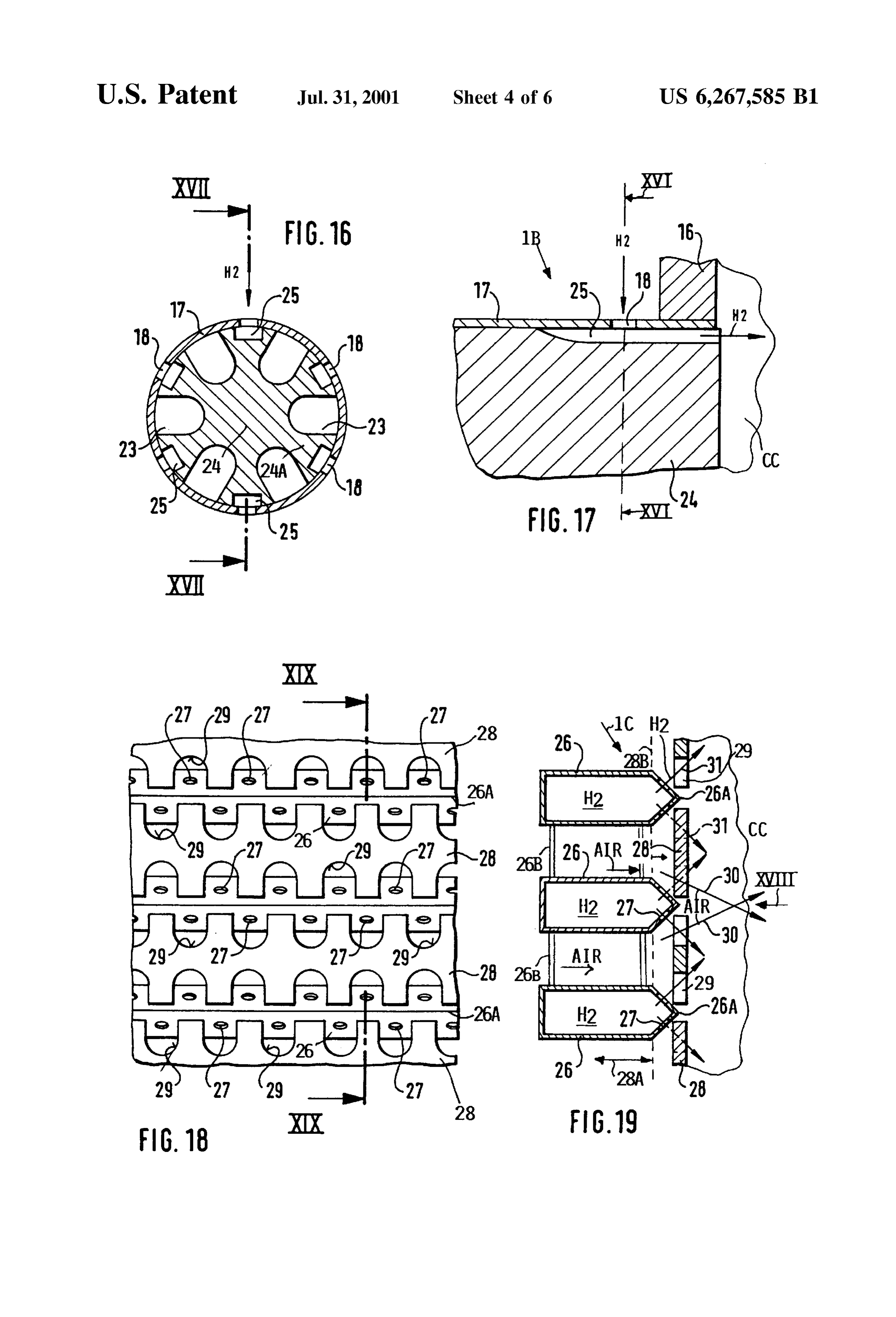
air/fuel mixture, which Strongly depends on the “turbulence 25 FIG. 15 is a view substantially in the direction of the intensity' as a measure of energy contained in the turbulence arrow XV in FIG. 14, showing an angular position of the air of the present diffusive microcombustion flames. distribution insert equal to FIG. 11; The foregoing features of the invention have certain FIG. 16 is a sectional view along section line XVI-XVI advantages, in addition to the unexpected NO reduction in FIG. 17, illustrating a modified air guide pin construction down to levels of 20% or less of comparable engines with a plurality of air guide channels and with a plurality of equipped with conventional combustors. These additional hydrogen guide channels, advantages of the invention are Seen in that the production FIG. 17 is a sectional view along section line XVII and technological effort and expense of the present com XVII in FIG. 16;
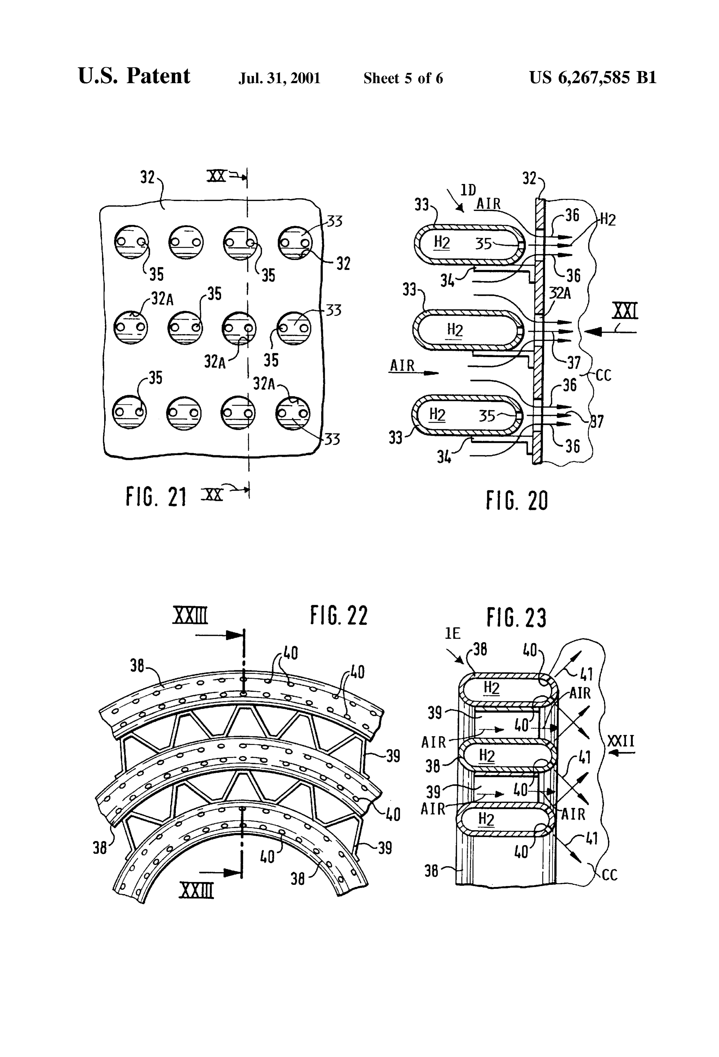
bustorS is Small since the formation of a large number of FIG. 18 is a view in the direction of the arrow XVIII in diffusive microcombustion flames without a respective num 35 FIG. 19, illustrating another embodiment of the present ber of hydrogen Supply tubes is simple. Still another advan hydrogen burner with hydrogen distribution channels each tage of the invention is seen in that the Supply of hydrogen having a multitude of hydrogen distribution holes, can be used as a cooling medium, especially prior to its FIG. 19 is a sectional view along section line XIX-XIX distribution into a multitude of diffusive microcombustion flames. Moreover, the invention has Succeeded in retaining 40 FIG. 18;
in the present diffusive micromixing the advantage of avoid FIG. 20 is a sectional view along section line XX-XX in FIG. 21 illustrating a further embodiment of the present ing flame flashbacks, which is inherent in diffusive combus hydrogen tion Systems, while simultaneously reducing the NO, for combustor with a plurality of hydrogen Supply mation in the exhaust gas. Such reduction cannot be channels with rounded side walls and a multitude of hydro achieved by conventional diffusive large Scale mixing. 45 gen distribution holes in one rounded Side wall facing the combustion chamber;
BRIEF DESCRIPTION OF THE DRAWINGS FIG.21 is a view in the direction of the arrow XXI in FIG. In order that the invention may be clearly understood, it 20;
will now be described, by way of example, with reference to FIG.22 is a front view in the direction of the arrow XXII the accompanying drawings, wherein: 50 in FIG. 23 illustrating yet another embodiment with circular FIG. 1 shows a plan view of a portion of a combustor as hydrogen Supply channels each having a multitude of hydro viewed in the direction of the arrow I in FIG. 2, illustrating gen distribution holes in a rounded Side wall facing the a matrix construction of a combustor that forms a back wall combustion chamber;
for a combustion chamber; FIG. 23 is a sectional view along section line XXIII FIG. 2 shows a sectional view along section line II-II in 55 XXIII in FIG.22; and
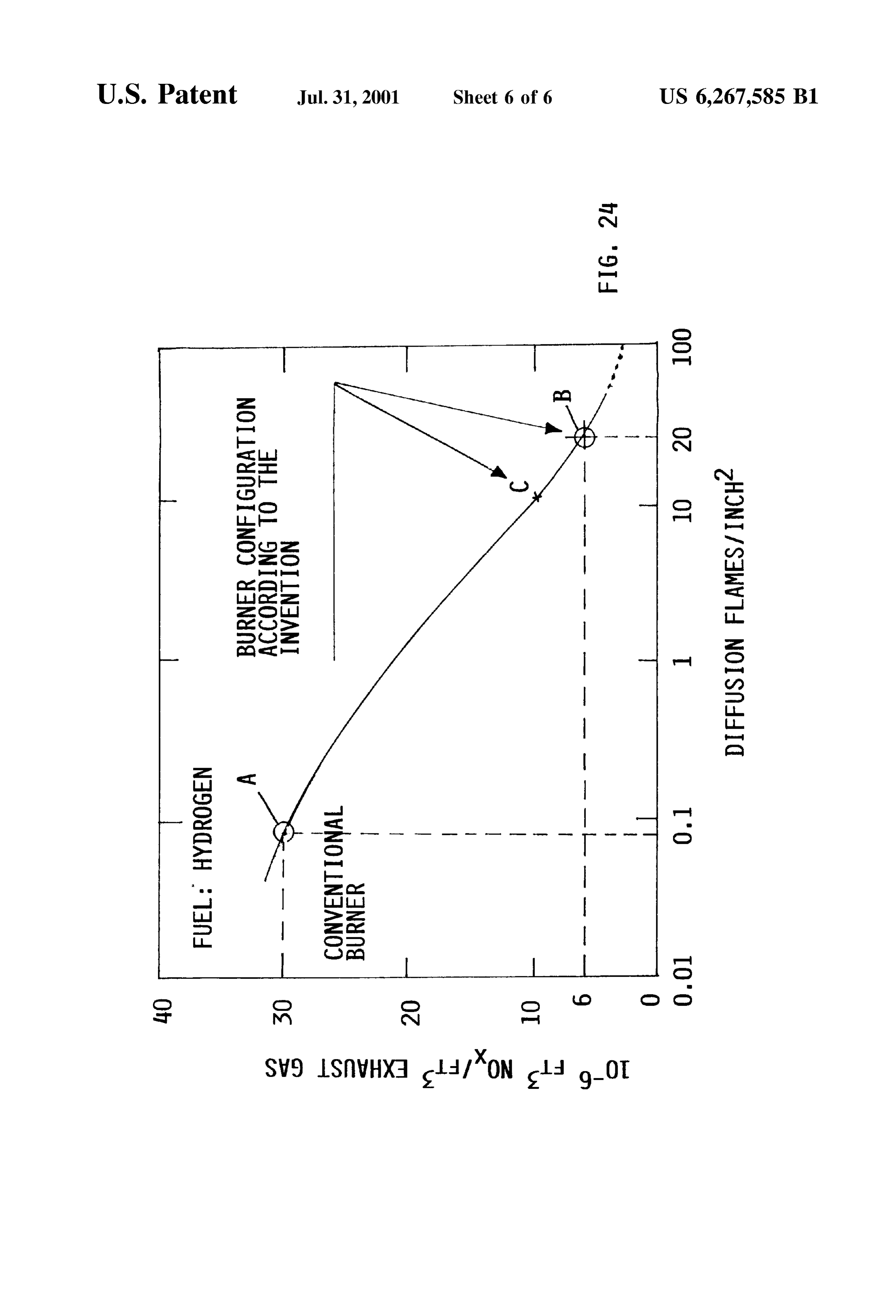
FIG. 1, wherein a porous combustor wall functions as a FIG. 24 is a diagram showing the NO, reduction in cubic micromix hydrogen distributor; foot-10' of NO, per cubic foot of exhaust gas as a function FIG. 3 shows a Side view of an air guide pin functioning of the number of diffusive microcombustion flames per as an air distributor in the burner of FIGS. 1 and 2; Square inch of combustor Surface area facing into the FIG. 4 is a sectional view in the direction of the arrows 60 combustion chamber.
IV-IV in FIG. 3 through the air guide pin;
FIG. 5 is a side view partially in section showing the air DETAILED DESCRIPTION OF PREFERRED guide pin inserted into an air guide tube of FIG. 2; EXAMPLE EMBODIMENTS AND OF THE FIG. 6 shows a view in the direction of the arrow VI in BEST MODE OF THE INVENTION FIG. 7, illustrating air distribution ridges with air flow holes 65 The invention will first be explained with reference to and wall Sections of porous material for hydrogen distribu FIG. 24 which illustrates test results performed with a gas tion; turbine engine model A320 APUGTCP 36-300. FIG. 24
Page 11
shows the content of NO, in cubic footx10 per cubic foot The perforated plate 2 is, for example, made of a Suitable of exhaust gas as a function of the flame density per Square heat resistant metal that is not gas permeable. The Second inch of the combustor Surface facing into the combustion perforated plate 3 is constructed according to the invention chamber. The tests were made under atmospheric conditions of a gas permeable material Such as a porous material, for which means that the absolute Nox levels measured in the example a sinter metal which will finely disperse the hydro tests are based on atmospheric burner entrance conditions. gen. Other Suitable materials are porous ceramics, metal The combustor had a surface area of 67.9 square inches fiber materials, other heat resistant porous materials and heat facing into the combustion chamber. In its original conven resistant perforated materials. Such as perforated sheet metal. tional form the combustor had six air injection nozzles While the apertures 2A and 3A may be arranged in any distributed over the combustor surface providing 0.088 desired pattern, the pattern must be the same in both plates diffusion flames per Square inch. Tests were run with the 2 and 3 So that the apertures register with each other to form conventional combustor using hydrogen fuel in one test and pairs of apertures 2A, 3A. The double-walled plate construc kerosene fuel in another test. The NO content in the exhaust tion is achieved by interconnecting the plates 2 and 3 gas was the same for both fuels, namely as shown at point through the tubes 4 which Serve as Spacers, plate intercon A in FIG. 24 showing 30x10 cubic foot of NO per one 15 nectors and air guides to form a large number of micromix cubic foot of exhaust gas for 0.088 diffusion combustion air jets. This number of micromix air jets is large enough if flames per Square inch of burner Surface. a Substantial reduction of nitrogen oxides in the exhaust gas A further test was made with the same engine, however, is achieved, e.g. down to at least 20% or less of the NO with a combustor modified as taught by the invention. The production in conventional burners of the same Size but with modified combustor had a total of 1600 micromix air jets a conventional, Small number of large combustion flames. and a corresponding number of diffusive microcombustion The plate 2 is, for example, soldered or welded or otherwise flames which amounts to approximately 24 diffusive micro bonded to the left-hand ends of the tubes 4 in the apertures combustion flames per Square inch of combustor Surface 2A. The right-hand air exit ends of the tubes 4 are preferably facing into the combustion chamber, (1600:67.9). Point B in provided with beaded radially outwardly bulging rings 5 FIG. 24 was obtained by repeating the test with hydrogen as 25 against which the Second plate 3 rests with a location fit fuel and air as oxidizer. Point B represents the invention and between each tube and the plate 3. The bulge 5 may be evidences a substantial reduction in the NO content of the formed by a flanging or crimping operation of the tubes 4. exhaust gas, compared to point A, namely about 6x10 The resulting location fit makes Sure that a dimensionally cubic foot of NO per cubic foot of exhaust gas compared to Stable double-walled plate Structure is obtained that encloses 30x10 cubic foot of NO per cubic foot of exhaust gas for a hydrogen distribution Space S. The hydrogen is in its point A. This result shows an eighty percent reduction in the gaseous form shown symbolically by an arrow GH2. The NO production by the invention compared to the prior art tube walls are closed along their entire length through the as represented by the tested engine A320 APUGTCP36–300 space S to prevent entry of hydrogen into the tubes, and to prior to the replacement of its original combustor by a prevent premixing in the tubes.
combustor as taught by the invention. FIG. 24 also shows at 35 According to the invention an air distribution and guide point C that for ten diffusive microcombustion flames per pin 6 shown on an enlarged scale in FIGS. 3 and 4 is Square inch of burner Surface the No production is still preferably inserted into each tube 4. Each pin 6 comprises a much reduced, namely 10x10 cubic foot of No per cubic central stem 8 surrounded by axial flutes 7 spaced by axial foot of the exhaust gas or only one third of the No volume lands 6B. In the shown example there are four flutes 7 and produced in the comparative conventional combustor. 40 four lands 6B. The flutes and lands Surround most of the FIGS. 1 to 7 illustrate combustor configurations in which length of the Stem 8, however, a portion of the Stem has a a Substantial number of micromix air jets, at least 10 per reduced diameter compared to the diameter of the lands 6B Square inch of burner Surface, is injected into a hydrogen and carries at its right-hand end a flange or disk 9 for guiding environment in a combustion chamber CC for generating a and deflecting micromix air jets as these jets emerge from corresponding number of diffusive microcombustion flames 45 the flutes 7 directly into the combustion chamber. The outer for an inverted diffusive combustion. diameter of the flange 9 corresponds approximately to the FIGS. 1 to 4 show a combustor 1 with a Surface area diameter of the lands 6B. At the opposite end, the pin 6 facing into the combustion chamber CC for the combustion carries stops 6A axially aligned with the lands 6B. These of hydrogen. This Surface area is available for the position StopS 6A are short in the axial direction, but have an outer ing of diffusive microcombustion flames. The combustion 50 diameter larger than the lands 6B for resting against the chamber CC is, for example, a part of a gas turbine. The outer surface of the wall 2. These pins 6 may be made as combustor 1 has the configuration of a double walled plate Solid elements as shown. The pins may be replaced by forming the rear wall of the combustion chamber CC. A axially short sheet metal disks with or without an axial Stem primary air flow marked by arrows "AIR” extends perpen extension as will be described below with reference to FIG. dicularly to the combustor surface area. Further details of the 55 14.
combustion chamber and its housing are not shown Since the FIG. 5 shows an example of the air distribution and guide combustion chamber may be of any desired conventional pin 6 inserted into a tube 4. For this purpose the flange 9 and construction. The combustor 1 comprises a first perforated the lands 6B have an Outer diameter providing a sliding fit plate 2 with first perforations 2A and a Second perforated into the inner diameter of the tube 4. The insertion takes plate 3 with second perforations 3A. The two perforated 60 place in the direction of the air flow from left to right and the plates 2 and 3 are interconnected by respective air guide StopS 6A bear against the plate 2 when the guide pin 6 is fully tubes 4 which keep the plates 2 and 3 at a constant distance inserted. The just described insertion and Selection of diam D from each other to enclose a hydrogen distribution Space eters holds the guide pins 6 firmly and permanently in the S. The perforations 2A and 3A may be arranged in accor tubes 4. The assembly shown in FIG. 5 forms an air injector dance with any desired pattern. The perforations 2A are, 65 and a multitude of Such injectors are mounted as shown in however, axially aligned with the perforations 3A to hold the FIG. 2 so that each tube 4 has its own injector, whereby the tubes 4 as shown in FIG. 2. air is distributed as shown by arrows 10 in FIG. 5 in the form

Page 12
of a large number of diffusive turbulent micromix air jets 10. wall Sections 13. The angular Stock Sections 13 and Sections Each pin 6 forms for example four micromix air jets Since formed as channel extension Sections are equally Suitable for each pin 6 has four air flow flutes 7, whereby four diffusive connecting channels 11 to each other. The free longitudinal microcombustion flames are formed by each pin 6. The total edges of the angular Stock Sections 13 are connected to number of micromix air jets is So Selected that according to respective longitudinal edges of the U-shaped hydrogen the invention there are at least ten, preferably at least twenty distribution channels 11, for example by welding, heat diffusive microcombustion flames per Square inch of the resistant brazing, or the like, So that one angular Stock burner Surface area facing into the combustion chamber CC. Section 13 interconnects two neighboring channels 11. Each Due to the deflection by the disks 9 and as shown in FIG. 5, Slanted wall of section 13 has the holes 14 uniformly spaced the air flow direction of the air jets 10 extends at about 45 from one another in the longitudinal direction as best Seen in relative to the hydrogen flow direction shown in FIG. 2. FIG. 6. The number of distinct micromix air jets is sufficient For operating the combustor 1 gaseous hydrogen shown if the production of NO is reduced as taught herein. by arrow GH is introduced into the space S between the The wall sections 13 as shown are slanted so that the walls 2 and 3 perpendicularly to the air flow which is blown primary air flow direction of the micromix air jets extends at Simultaneously through the tubes 4 into the combustion 15 about 45 across the direction of the hydrogen flow direction chamber CC. The porous wall 3 diffuses the hydrogen as indicated by the arrows H. However, the sections 13 may shown by the horizontal arrows H. in a very fine have alternatively a Square Sectional configuration, whereby distribution, thereby forming a hydrogen environment in air through the holes 14 would travel at right angles or a which the hydrogen is uniformly distributed. The air blown mixing angle of 90 to the hydrogen flow direction H. A into the combustion chamber is distributed in the form of a domed configuration of the sections 13 may be feasible conical mantle shown by arrows 10 in FIG. 5 due to the instead of the angled or Squared Sectional configuration as position of the disk 9. However, the conical mantle is long as the intended high mixing intensity is achieved in the divided into four sectors by the four lands 6B, whereby four diffusive microcombustion flames.
distinct diffusive microcombustion flames are generated per In order to operate the burner 1A, gaseous hydrogen H2 tube 4 that together have a rotational Symmetry relative to 25 is introduced into the distribution channels 11 while simul the central longitudinal axes through each of the tubes 4. In taneously blowing air through the holes 14 into the com any event, the number of diffusive microcombustion flames bustion chamber CC. The hydrogen flows inside the distri is Selected as has been explained above with reference to bution channels 11 crosswise to the primary air flow FIG. 24. direction and a fine hydrogen distribution or diffusion takes The activation of the air hydrogen micromixing process is place through the porous wall 12 to form a hydrogen enhanced by the interaction of neighboring conical flame environment in the combustion chamber CC. Due to the air Sectors that impinge on each other. The geometry of the injection into the hydrogen environment a mixing Zone is guide pins 6 is so selected that with the insertion of the pins Sustained in the area of each hole or bore 14 and each Zone 6 into the tubes 4 until the StopS 6A engage the plate 2, a forms its own distinct diffusive microcombustion flame, predetermined air deflection pattern is achieved which 35 whereby excessively high temperature Zones are prevented results in a predetermined flame configuration for each or quickly dispersed and the NO, formation is correspond individual diffusive microcombustion flame in the combus ingly reduced.
tion chamber. In this connection it is quite possible to omit The burner 1A of FIG. 7 has an especially simple con the StopS 6A altogether to reduce weight. In that case the struction that can be bent out of sheet metal to form the guide pins 6 will be inserted into the air guide tubes 4 with 40 shown U-shaped channel croSS-Section. Each U-leg is pref the help of an assembly jig So that each pin is inserted to the erably integrally connected with an angular Section 13 that correct extent. Due to the present Simple construction of the is already perforated with the holes 14. Thereafter, the air injectors the injectors can be miniaturized and mass U-channels are closed by the porous wall Sections 12 and the produced, whereby a Substantially larger number of Such individual Sections are welded to each other along the ridges injectors can be installed for each combustion chamber than 45 13A of two neighboring perforated Sections forming the was possible heretofore. Due to the miniaturization which angular Sections 13. The burner 1A can be miniaturized to results in diffusive microcombustion flames each of which Such an extent that Several thousand diffusive microcom has a diameter of about 2 mm. bustion flames can be formed on the Surface of the burner FIGS. 6 and 7 illustrate another embodiment of a com facing into the combustion chamber CC. bustor 1A according to the invention for the injection of air 50 In the burners 1 and 1A described above, a fine distribu jets into a hydrogen environment. The combustor 1A com tion of hydrogen is achieved by porous walls 3 or 12 by prises Several elongated individual hydrogen distribution introducing hydrogen either through the distribution Space S channels 11 each having a U-shaped cross-section with one or through the distribution channels 11. In operation the channel Side closed by a porous wall 12, for example, made hydrogen is Supplied to thousands of distinct diffusive of Sinter metal or the like for passing hydrogen through the 55 microcombustion flames, whereby a micromix diffusion walls 12. The length of the channels 11 extends perpendicu combustion of the hydrogen takes place. The present burners larly to the drawing plane. The channels 11 are intercon or combustors of FIGS. 1 to 7 form a hydrogen environment nected with each other by wall sections 13 provided with a within the combustion chamber CC. The injection of a large multitude of holes 14 for dividing the air flow indicated by number of air jets into this hydrogen environment results in the arrow AIR into a large number of distinct micromiX air 60 an inverse diffusion combustion which is capable of stabi jets which in turn form a respective or corresponding lizing itself with a turbulent flow characteristic in the number of also distinct diffusive microcombustion flames in resulting diffusive microcombustion flames. The essential the combustion chamber CC without any premixing. The advantage of this inverse hydrogen diffusion combustion of Sections 13 are preferably perforated angular Stock, or may the invention resides in that the hydrogen is efficiently used be extensions of the walls of the channels 11 to form ridges 65 for cooling the Structure of the combustor including the 13A, e.g. by welding or Soldering. Heat resistant sheet metal tubes 4 of the rear wall forming the burner of the combustion is Suitable for making the channels 11 and the perforated chamber CC while substantially reducing the formation of
Page 13
nitrogen oxides compared to conventional burners as has in the respective tubes 17 So that each hydrogen jet through been explained above with reference to FIG. 24. the holes 18 is injected into its corresponding airStream, Instead of using porous Sinter metals for making the plate whereby in operation for example Six diffusive microcom 3 and the wall sections 12 of the above described combustors bustion flames are formed by each guide pin 19 having Six 1, 1A these elements 3 and 12 can be made by using other 5 lands 21 and six flutes 23 cooperating with six holes 18 in the wall of the respective tube 17 for the injection of porous materials. Such as porous metal fibers, for example hydrogen “felt metal' can be used for the present purposes. to the air jets Hinto Six micromix air streams at a 90° angle flow direction.
Furthermore, porous ceramic materials can be used for the In order to operate the burner or combustor 1B a large plate 3 and the wall sections 12. In order to limit any effects number of micromix air jets is blown through the tubes 17, that may occur due to the fact that the pores in a porous more Specifically through the flutes 23 of the air guide pins material are inhomogeneously distributed, it is Suggested 19 from left to right into the combustion chamber CC. that a perforated sheet metal with a very fine uniform hole Simultaneously, hydrogen distribution is arranged in Series with a relatively thin layer the direction Substantially isperpendicularly introduced into the Space S in to the air flow of a porous material. Alternatively, it is possible to entirely 15 direction as indicated by the arrow replace the porous material walls by a thin Sheet material hydrogen passes through the holes 18 next to the GH in FIG. 9. As the provided with a multitude of fine diameter holes. The pore chamber, the hydrogen jets are entrained by thecombustion Size and or the hole diameter for the passage of hydrogen through the respective flutes 23 and move withairstreams the air must be Such, that Sufficient hydrogen is provided to Sustain streams into the combustion chamber CC whereby the the combustion in the large number of diffusive microcom micromiX air jets Sustain a turbulent micromix diffusion flow bustion flames.
and the production of NO in the exhaust gas of the
FIGS. 8 to 17 show a further combustor 1B according to combustion chamber CC is reduced as described above. A the invention working on the basis of regular micromix diffusive microcombustion flame is formed downstream of diffusion combustion rather than on the basis of an inverse each of the multitude of holes 18. Once ignition has diffusion as in FIGS. 1 to 7. In FIGS. 8 to 19 hydrogen is 25 occurred, these diffusive microcombustion flames are Stabi injected into a high Velocity air environment. lized and remain distinct flames. The burner 1B comprises, as the other embodiments, two Since each tube 17 comprises, for example, six holes 18, perforated plates 15 and 16 spaced from each other by tubes and assuming the burner 1B comprises 500 tubes 17, a total 17 mounted in the perforations for a hydrogen fuel distri of 6x500=3000 diffusive microcombustion flames are bution perpendicularly to a primary flow direction. Each formed when operating the combustion chamber. Such a tube 17 has an air inlet port and an air outlet port directly into Structure provides a Substantial increase in the number of the combustion chamber CC. Hydrogen fuel enters the diffusive microcombustion flames compared to conventional diffusive microcombustion Zones through holes 18 passing burners. Application of the present teaching of the invention through the walls of each tube 17 as close as possible to the to the above mentioned combustor as published in TRUD exit port of each tube next to the combustion chamber CC. 35 would increase the number of installable combustion Zones The holes 18 are preferably uniformly distributed around the by a factor of about 40. This large number of diffusive circumference of each tube 17 with equal angular on-center microcombustion flames reduces the NO production to less spacings from one hole 18 to the next hole 18. As shown in than 20% of the NO production in a conventional burner of FIG. 9, the cross-sectional flow area of the holes 18 is comparable size but with few large combustion flames. Smaller than the cross-sectional flow area of the tubes 17 and 40
The teaching of the invention results in all embodiments the flow direction of distinct hydrogen jets shown by arrows in a high degree of micromixing of the air with the hydrogen He is at a right angle to the air flow direction through the without any premixing, and with a Substantially reduced tubes 17.
mixing Scale compared to conventional combustors. AS a
As shown in FIGS. 10 to 13, an air distribution and guide result, the generation of nitrogen oxide is reduced to a pin 19 is preferably inserted into each tube 17. Each pin 19 45 Surprising extent, See FIG. 24. It is possible to adjust the comprises a plurality of air guide lands 21 spaced by air present burner with regard to the air introduction by rotating guide flutes 23 around a stem 19A. Each air guide flute 23 the air guide pins 19 in the respective tubes 17 to thereby extends axially between two air guide lands 21 of the pin 19, achieve different mixing ratios in the burner 1B. The stops but not along a stem extension of the stem 19A. The stem 20 may, however, be omitted. In that case, the extent of the extension forms a reduced diameter free flow guide Surface 50 axial insertion of the guide pins 19 into the tubes 17 will be 22. determined by a mounting jig at the time of manufacturing The air guide pins 19 may be replaced by sheet metal and assembly.
inserts I which have orifices 23A which function as air FIGS. 10 to 13 show different rotational adjustments of distributors as shown in FIGS. 14 and 15 described in more the guide pin 19 in the tube 17. In FIGS. 10 and 11 the air detail below. 55 guide flutes 23 are aligned with the hydrogen Supply holes The free flow guide surface 22 cooperates with the holes 18. In FIGS. 12 and 13 the lands 21 of the guide pins 19 are 18 in guiding the air and hydrogen flow. At its other end aligned with the holes 18 in the tubes 17 but stop short of opposite the free flow guide surface 22 the pin 19 carries covering the holes 18 between air streams through the flutes stop elements 20 that bear against the wall 15 of the 23. FIG. 13 also shows the guide pin 19 inserted axially into combustor 1B to limit the insertion depth. The radial depth 60 its tube 17 to Such an extent that the land 21 reaches with its of the flutes or grooves 23 reaches preferably to the diameter right-hand end almost to the respective hole 18. AS a result, of the Stem extension providing the free flow guide Surface the hydrogen jet H can be diverted only into the combustion 22. However, the flute depth may be slightly less than the chamber CC along the air guide Surface 22 of the extension Stem diameter, whereby a Smooth curved transition guSSet is of the stem 19A. However, if the axial length of the lands 21 formed between the end of a land 21 and the reduced 65 of the guide pins 19 is shorter or sheet metal inserts I are diameter stem extension as seen in FIGS. 10 and 13. The inserted to a lesser axial extent as shown in FIG. 14, the number of flutes 23 corresponds to the number of holes 18 hydrogen jet H passing through the holes 18 will be
Page 14
divided. A hydrogen portion H" will flow in a countercurrent for example a roof with a ridge 26A with hydrogen exit direction relative to the air flow, whereby a certain recircu through-holes 27 through both sides of the roof ridge 26A. lation is generated that further improves the mixing of air Thus, the channels 26 have a closed croSS-Section except for and hydrogen directly next to the combustion chamber CC. the through-holes 27 through which hydrogen jets 31 pass These FIGS. are shown on an enlarged scale. rather than through porous wall sections 12 as shown in FIG. FIGS. 14 and 15 show an embodiment with heat resistant 7. The air flows from left-to-right through the passages sheet metal air guide inserts I having a head plate with webs between the channels 26 held apart by the spacers 26B. A W between air guide orifices 23A. The head plate with its gap grid Structure is formed for example of heat resistant webs W may be secured to a stem 22 that serves the same sheet metal Strips 28 interconnected by connector elements purpose as the air guide surface 22 in FIGS. 10 and 13. not shown. These connector elements hold the grid forming However, the stem 22' may be omitted, whereby the air Strips ridges 28 Spaced from each other in Such positions that the 26A are aligned with gaps between neighboring Strips guide insert I would be just a disc with webs W and orifices 28 as seen in FIGS. 18 and 19. The strips 28 are provided 23A. Air jets passing through the air guide orificeS 23A flow directly past the holes 18, whereby the hydrogen jets H, H' with cut-outs 29 best seen in FIG. 18. The sheet metal strips impinge on the air jets at a right angle for an excellent 15 28 with the cut-outs 29 are so arranged between two mixing. However, the hydrogen jets may be directed to hydrogen distribution channels 26 that the through-holes 27 in the Slanting wall portions forming the roof with the ridge impinge on the air Streams at an angle other than a right 26A align with the cut-outs 29. The arrangement is such that angle, for example by directing the holes 18 at a respective the through-holes 27 in one Slanting wall portion are Stag angle through the wall of the respective tube 17. In all of the gered relative to the holes in the opposite Slanting wall just described embodiments, a fine diffusive micromixing of portion of the channels 26. Similarly, the cut-outs 29 and the the hydrogen jets passing through the holes 18 into the air intermediate lands between the cut-outs 29 in one strip 28 Streams is assured So that a micromix diffusive combustion are Staggered relative to the lands in a neighboring Strip 28 is obtained. The individual diffusive microcombustion So that lands in one Strip face cut-outs in the other Strip and flames will have a diameter of only about 2 mm each. In this vice versa as seen in FIG. 18. The hydrogen distribution type of micromixing of air and hydrogen the individual 25 channels 26 and the strips 28 are preferably so oriented diffusive microcombustion flames stabilize themselves, fre relative to each other that each through hole 27 registers with quently directly at the holes 18. By stabilizing themselves one cut-out 29. However, instead of aligning just one the diffusive microcombustion flames remain distinct. AS through-hole 27, several such holes 27 of Small diameter and mentioned above, the air guide Stem 22' could be omitted, arranged close to each other may be aligned with one cut-out especially where the air guide orificeS 23A are directly 29 to feed hydrogen jets 31 through the cut-outs 29 for aligned with the holes 18 as shown in FIG. 15. In all micromixing with air also flowing through these cut-outs 29 embodiments shown in FIGS. 9 to 15 the hydrogen jets enter as shown by the air jets representing arrows 30 and the the airstream at an angle of 90 degrees for an efficient hydrogen jets representing arrows 31 in FIG. 19. mixing. As shown in FIG. 19, the Hijets 31 extend at an angle of FIGS. 16 and 17 show a further modification of an air 35 about 45 across the air flow direction 30. However, the guide pin 24 in the present burner IB, whereby the hydrogen crossing angle may be varied by Shifting the Strips 28 to the jets and the air jets are guided Separately until they enter into left or right as shown by the arrow 28A in FIG. 19 for the combustion chamber CC. In this embodiment the tubes optimizing the micromixing intensity. FIG. 19 shows the gap 17 are also provided with holes 18 at their exit end next to strips 28 positioned just downstream of the roof section 26A. the combustion chamber as described above. These tubes 17 40 By shifting the strips 28 slightly to the left the strips 28 are held between mounting plates 15 and 16 as described. would be positioned just upstream of the through-holes 27 as The air guide pin 24, however, is provided with air guide shown by the dashed line 28B. In any position of the strips flutes 23 and Separate hydrogen guide channels 25 at the 28, the cut-outs 29 determine the air flow direction 30 which discharge end of the guide pin 24 next to the combustion may be Selected to extend parallel to the primary flow chamber CC. The hydrogen guide channels 25 are formed in 45 direction in FIG. 19 by respectively adjusting the position of the lands 24A at the ends thereof between the flutes 23. The the strips 28 with the adjustment mechanism 28A which as hydrogen guide channels 25 extend axially in parallel to the Such may be conventional. Similarly, the angle of the roof flutes 23. The air guide pins 24 are inserted into the tubes 17 section 26A which is shown to be about 90° in FIG. 19 may So that each hole 18 leads into the respective hydrogen guide be varied to optimize the H-air-mixing rate. The through channel 25. As a result, hydrogen is diffused into the air in 50 holes 27 may be positioned in the side walls of the channels an area downstream of the wall 16 in the combustion 26 close to 28B in FIG. 19 for ejecting the hydrogen jets 31 chamber CC. This feature has the advantage that the gen in a direction perpendicular or at 90 to the primary air flow eration of a multitude of diffusive microcombustion flames direction.
takes place inside the combustion chamber CC, whereby In order to operate the combustor 1C, air is caused to flow excessive thermal loads on the Structural components espe 55 from left-to-right through the Spaces between the channels cially of the burner itself are further reduced. The diffusive 26 and through the cut-outs 29 as indicated by the arrows 30 microcombustion flames Stabilize themselves at the exit thereby forming a large number of micromix air jets. ports of the hydrogen guide channels 25. Simultaneously, hydrogen passes through the through-holes FIGS. 18 and 19 show a further embodiment of a burner 27 as indicated by the arrows 31. In this arrangement an air or combustor 1C according to the invention for generating a 60 environment is formed in the combustion chamber CC and regular diffusion combustion, wherein hydrogen is injected diffusive microcombustion flames are formed around the into high velocity air streams. The burner 1C is a relatively through-holes 27. The respective diffusive microcombustion flat Structure formed to have hydrogen guide channels 26 flames stabilize themselves at the through-holes 27 and held together by spacer members 26B to form between the thereby each flame remains distinct from any other diffusive channels 26 air flow passages through which air can freely 65 microcombustion flame on the burner Surface. flow. Each channel 26 has a Substantially rectangular or FIGS. 20 and 21 show a further embodiment of a present U-shaped cross-section except for an end Section forming burner 1D with a perforated plate or wall 32 preferably
Page 15
formed as a single wall Section with apertures 32A therein. provided. The upper limit of several thousand diffusive A plurality of hydrogen Supply channels 33 are Secured to microcombustion flames distributed over the entire available the apertured plate 32 by brackets 34. A combustion cham burner Surface facing into the combustion chamber is ber facing side wall of each channel 33 is provided with reached on the one hand when the miniaturization is no hydrogen discharge holes 35 and the channels 33 are aligned 5 longer economically feasible, or technically when the dif with the holes 32A in the wall 32 so that the hydrogen fusive microcombustion flames are no longer Stable due to discharge holes 35 register with the holes 32A. The channels the high number of flames per Square inch. 33 have an elongated cross-section with rounded side Although the invention has been described with reference Surfaces, one of which is provided with the hydrogen exit to specific example embodiments, it will be appreciated that holes 35 facing the combustion chamber CC. A multitude of it is intended to cover all modifications and equivalents such holes 35 is provided and FIG. 21 illustrates that at least within the Scope of the appended claims. two hydrogen exit holes 35 are aligned with each hole 32A What is claimed is:
in the wall 32. Hydrogen is discharged as indicated by the 1. A combustor for diffusion combustion of hydrogen fuel arrow 37 while air is discharged as indicated by the arrows and air as an oxidizer in a combustion chamber in which 36 shown in FIG. 20, whereby again a very efficient and 15 exhaust gas including nitrogen oxides NO is produced thorough micromixing of air and hydrogen is achieved in the during combustion, Said combustor comprising a burner required number of diffusive microcombustion flames. Surface area facing into said combustion chamber (CC), a In order to operate the burner 1D, air is caused to flow number of hydrogen fuel inlet through-holes in Said com from left-to-right past the channels 33 to pass through the bustor for feeding a corresponding number of hydrogen jets large number of holes 32A into the combustion chamber CC, (31) into said combustion chamber, a number of air inlets in whereby an air environment is formed inside the combustion said combustor for feeding air streams (30) into said com chamber into which the hydrogen is blown as indicated by bustion chamber, Said hydrogen fuel inlet through-holes and the arrows 37 to generate a multitude of diffusive micro Said air inlets being So positioned relative to each other and combustion flames in the vicinity of each of the holes 35 relative to said combustion chamber that stable and distinct around which the flames Stabilize themselves once ignition 25 diffusive microcombustion flames are formed in Said com has occurred. bustion chamber by diffusion micromixing hydrogen jet and FIGS. 22 and 23 show another embodiment of a burner 1E air jets with a mixing intensity that depends on a pressure according to the invention similar to that of FIGS. 20 and 21, drop available in Said combustion chamber to Sustain a multitude of said stable and distinct diffusive microcombus except that the channels 38 for the hydrogen Supply in the tion flames for maintaining said nitrogen oxides NO at most burner 1E are circular or Semicircular. The cross-section of the channels 38 is substantially the same as in FIG. 20, exhaust at a level of 10x10 cubic foot of NO, per cubic foot of said except that the hydrogen exit holes 40 are positioned at an gases during combustion as measured at atmo angle relative to a horizontal plane as shown by the hydro spheric burner entrance conditions, said combustor further gen arrows 41. Preferably, each supply channel 38 forms a 35 comprising a plurality of hydrogen distribution channels closed ring of radially inwardly progressively Smaller diam (26) with air flow spaces between said channels, channel eter. These rings are mounted together by corrugated Spacer walls enclosing each of Said hydrogen distribution channels, strips 39, for example welded to the ring channel 38. These Said channel walls including wall Sections forming at least Spacer Strips 39 permit the free passage of the air through the part of Said burner Surface area facing into Said combustion Spaces between neighboring rings 38. chamber (CC), said through-holes (27) formed in said wall It is possible to form the hydrogen supply channels 38 and Sections for feeding hydrogen jets (31) through said through
the spacer strips 39 of a material that will permit winding holes (27)into holes (27) said combustion chamber (CC), said through extending through said wall Sections So that a these elements into a flat coil to form a disk-shaped or hydrogen flow ring-shaped burner 1E. Such a coil would have a spiral at a first angle todirection of Said hydrogen jets (31) extends shape. In both instances a multitude of holes 40 is positioned 45 structure (28) with cut-outsof(29) a Surface Said wall Sections, and a grid to face into the combustion chamber CC in an angular for controlling an air flow directionin (30) said grid structure (28) direction whereby two hydrogen jets croSS each other as passing through said grid structure (28), of said air jets (30) said grid structure indicated by the arrows 41, except for the upwardly facing (28) being so positioned relative to said through-holes (27) hole 40 in the outer ring channel 38 and the downwardly that said air jets (30) passing through said cut-outs (29) and facing hole 40 in the inner ring channel 38. The ring 50 said hydrogen jets (31) passing through said through-holes channels and the Spirally wound ring channels have a curved (27) cross one another at a second angle to form said stable shape as shown. Both embodiments operate in the same and distinct diffusive microcombustion flames. manner with the same effect as described above in connec tion with FIGS. 18 to 21. 2. The combustor of claim 1, wherein two of said wall Sections of Said channel walls form a roof with a ridge
The burners IC and ID as shown in FIGS. 18 to 21 may 55 (26A), and wherein said grid structure (28) is positioned easily be varied to accept circular configurations similar to downstream of Said wall Sections of Said channel walls. the burner IE shown in FIGS. 22 and 23, if such a design 3. The combustor of claim 1, wherein said grid structure better fits the gas turbine interface conditions, for example. (28) is positioned upstream of Said ridge forming side wall The present miniaturization finds the lower limit of the Sections (26A).
number of diffusive microcombustion flames per Square inch 60 4. The combustor of claim 1, further comprising position of burner Surface area facing into the combustion chamber adjustment means (28A) connected to said grid structure at a point where a significant drop in the NO production (28) for moving said grid structure back and forth between occurs as explained above with reference to FIG. 24. A an upstream position (28) and a downstream position (28B). practical lower number of Such flames may require at least 5. The combustor of claim 1, wherein said ridge forming 10 diffusive microcombustion flames per Square inch of 65 Side wall Sections (26A) carry two rows of Said through burner Surface facing into the combustion chamber CC. holes (27) in such positions that the through-holes in one Preferably at least 20 such flames per square inch should be wall Section are Staggered relative to the through-holes in the
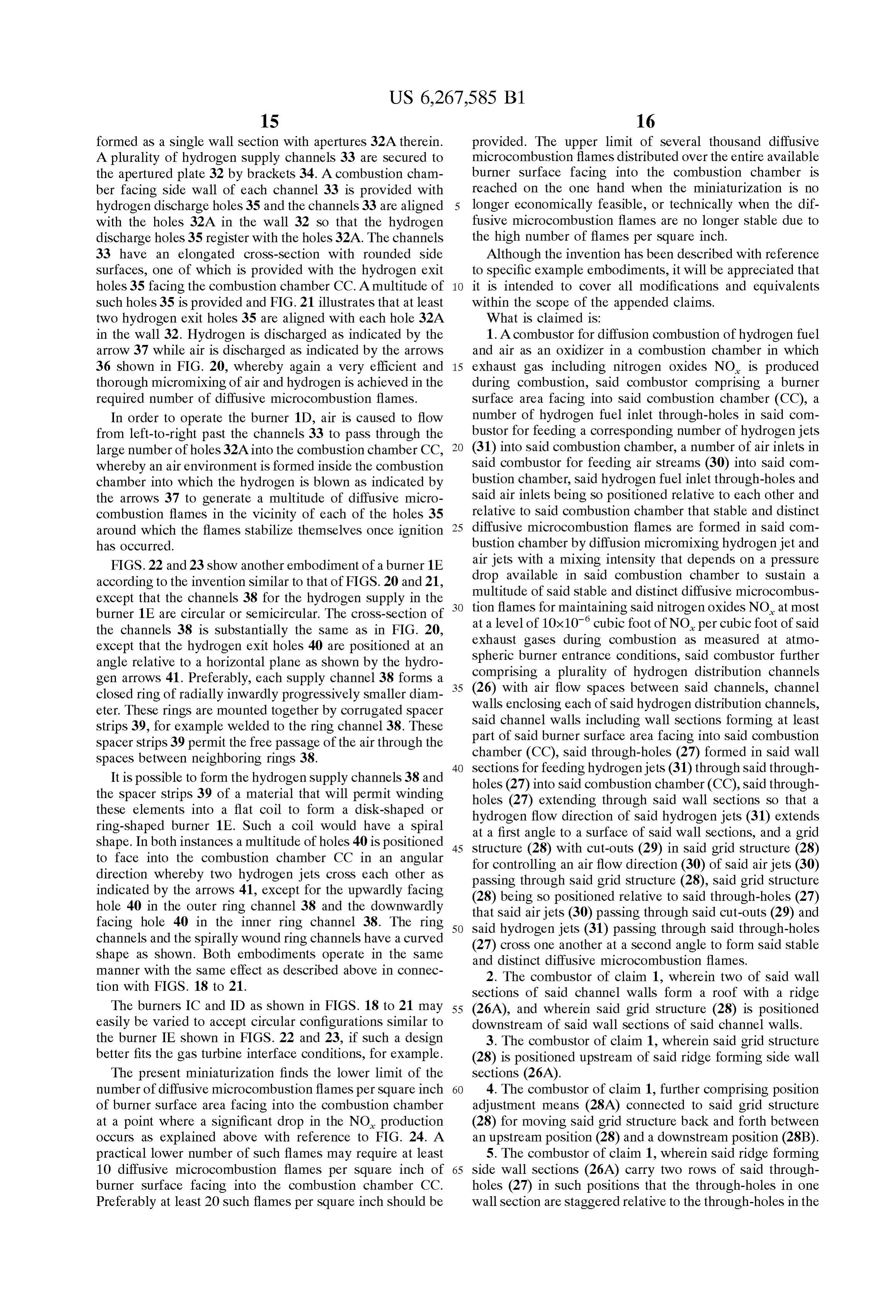
Page 16
opposite wall Section, and wherein Said grid structure (28) 7. The combustor of claim 1, wherein said through-holes comprises a plurality of grid strips having cut-outs (29) cut (27) are positioned on the side walls of the hydrogen into Said grid Strips (28A) along opposite edges of said grid distribution channels (26) close to a position (28B) for Strips, said cut-outs (29) being aligned with said through- ejecting hydrogen in a direction perpendicular to the primary holes (27). 5 flow direction.
8. The combustor of claim 1, wherein said hydrogen 6. The combustor of claim 1, wherein said diffusive microcombustion flames have a diameter of 2 mm at the distribution channels (26,38) have a circular shape.
moSt. k . . . .
Page 17
UNITED STATES PATENT AND TRADEMARK OFFICE
CERTIFICATE OF CORRECTION
PATENT NO. : 6,267,585 Bl Page of
INVENTOR(S) : Suttrop
It is certified that error appears in the above-identified patent and that said Letters Patent is hereby corrected as shown below:
Title page,
Item 63, insert the following item:
30 Foreign Application Priority Data
Item (56), OTHER PUBLICATIONS, line 5, replace “Fulled" by -- Fueled --; Item 57, ABSTRACT, line 8, after "high", replace "nixing by -- mixing --; line 9, replace "micorcombustion' by -- microcombustion --; Column 13
Line 33, after "airstream at', replace "an' by -- a mixing --; Column 15
Line37, after "ring, replace "channel" by -- channels --.
Signed and Sealed this
Nineteenth Day of March, 2002
JAMESE. ROGAN
Attesting Officer Director of the United States Patent and Trademark Office
Provenance
- Collection
- Cited prior art
- Original PDF
- patentimages.storage.googleapis.com →
- Filed
- 1999-05-07
- Pages
- 17
- Method
- pdftotext (the PDF's own text layer) + pdftoppm 300dpi page scans
- Source
- Google Patents bibliographic record
- Granted
- 2001-07-31
- Inventors
- Friedemann Suttrop; Airbus Operations GmbH
- Transcribed from
- patentimages.storage.googleapis.com →