patent · US5435343
Two stage natural/LP gas convertible pressure regulator valve with single servo controller
25 July 1995
Page 1 — bibliographic record
United States Patent (19 11 Patent Number: 5,435,343 Buezis 45. Date of Patent: Jul. 25, 1995 54 TWO STAGE NATURAL/LP GAS Attorney, Agent, or Firm-Charles L. Rubow CONVERTIBLE PRESSURE REGULATOR 57 ABSTRACT
WALVE WITH SENGLE SERVO
CONTROLLER A convertible two-stage pressure regulator in which a 75) Inventor: James G. Buezis, Plymouth, Minn. main valve regulates fluid flow between an inlet and outlet in response to a control pressure produced by a 73 Assignee: Honeywell Inc., Minneapolis, Minn. servo regulator valve, the control pressure depending 21 Appl. No.: 203,972 on outlet pressure and the force provided by a regulator spring to a diaphragm carrying a servo regulator valve 22 Filed: Mar. 1, 1994 closure element. Compression of the regulator spring is 51 Int. Cl...................... G05D 16/06; G05D 16/16; controlled by a solenoid armature in a plunger assembly GOSD 16/20 which is selectively positionable by a selector knob to 52 U.S.C. ............................... 137/489; 137/505.14; obtain higher or lower regulator spring force. Adjust 25/129.18 able stops provide for individual adjustment of low and 58) Field of Search ........................... 137/505.14, 489; high outlet pressures for each of two pressure ranges. 251/129.18, 129.19 Substantially identical air gaps in the magnetic circuit of the solenoid are provided for both pressure ranges by a 56 References Cited magnetic pole piece in the plunger assembly which
solenoid armature which extends beyond the solenoid 4,850,530 7/989 Uecker . coil in the opposite direction. Primary Examiner-Gerald A. Michalsky 21 Claims, 3 Drawing Sheets
Page 2
Drawing sheet — no readable text.
Page 3
Drawing sheet — no readable text.
Page 4
Drawing sheet — no readable text.
Page 5
mechanism co-axial with the plunger assembly. The
TWO STAGE NATURAL/LP GAS CONVERTBLE stop mechanism includes two parts having facing ends PRESSURE REGULATORVALVE WITH SINGLE formed at an angle different from perpendicular to the SERVO CONTROLLER axis, so that as the first partis rotated with respect to the second part, the second part is axially displaced. The
BACKGROUND OF THE INVENTION second part is mechanically coupled to the solenoid The present invention relates generally to fluid pres armature so as to change the unactuated and actuated Sure regulators, and, more specifically, to two-stage positions of the armature relative to the solenoid coil, pressure regulating valves convertible without parts 10 thereby changing the unactuated and actuated compres replacement to separate output pressure ranges, such as Sions of a regulator spring.
those typically used in natural and LP fuel gas controls. This design accommodates only a single low firing Applications have existed for some time for pressure rate adjustment and a single high firing rate adjustment. regulating valves capable of regulating to either of two Accordingly, the valve must be adjusted for low and electrically selected pressures. In general, these applica high firing rates each time it is converted between natu tions have been somewhat specialized, and the required 5 ral and LP gas usage. Obviously, it would be preferable volumes relatively small, thus providing little incentive to be able to convert between usages in different gas for exploring nontraditional designs. To the extent two applications without requiring firing rate adjustments. Stage pressure regulating valve designs are known, they An additional disadvantage of this design is that repo generally employ a solenoid actuator to change the sitioning the solenoid armature relative to the coil for force supplied by a regulator spring. conversion between pressure ranges suitable for natural A pressure regulating valve application which is re and LP gas respectively changes the air gaps in the ceiving increasing interest is fuel gas control for small magnetic circuit, thereby resulting in a less than opti furnaces, such as those used in single family residences, including both permanent fixed location homes and mum ranges.
solenoid configuration for one or both of the mobile homes. Certain U.S. furnace manufacturers have 25 developed high efficiency furnace designs which rely ation, Although gas valves are available for two-stage oper on two stages of furnace operation. When heat is first conversion and gas valves are available which provide for called for, and under moderate heat requirements, the need exists for without parts replacement, an increasing furnace is fired at a low to moderate rate. If firing at that objectives, as well a single gas valve which achieves both rate does not provide the heat output required for exist minimum valve adjustments, as permitting conversion with no or ing conditions, firing is stepped to a higher rate. and providing uniform solenoid performance regardless
Another factor which impacts gas valve manufactur for which the valve is set. The applicant of the pressure range ers and users is that both natural gas and gas produced design for such a valve which retains the advantageous has devised a from liquefied petroleum (LP) or propane are in con features of prior limited purpose designs, while adding mon use as fuel gases. These gases have different burn 35 ing characteristics and are supplied to a furnace or other the capability of two-stage operation, no parts replace ment conversion, and conversion without firing rate burner apparatus under different pressures. Specifically, adjustments.
gas generated from liquefied petroleum has a faster flame front. Accordingly, it is supplied to a burner at a SUMMARY OF THE INVENTION higher pressure, e.g., 10 inches H2O, which induces 40 more oxygen entrainment. In contrast, natural gas is The invention is a pressure regulator having first and typically supplied to a furnace or burner at a pressure of second electrically determinable stages of operation in 3.5 inches H2O. Accordingly, a pressure regulating gas each of two pressure ranges which may correspond to valve for a furnace or other appliance must regulate to pressure ranges suitable for natural and LP gas usage a higher pressure for LP gas than for natural gas. 45 respectively, the pressure regulator including flow con There are various situations in which it is not known trol means operable to vary fluid flow as a function of at the outset which type of fuel gas will be used, and/or extension of a regulator spring. Extension of the regula in which the type of fuel gas may be changed at some tor spring is determined in part by solenoid apparatus point during the operating life of a furnace or other including a movable support assembly extending along appliance. Either situation often occurs with a mobile SO an axis through an opening through the solenoid coil, home. Another common situation arises in connection the movable support assembly being moveable along with new construction of permanent fixed location the axis and biased away from the regulator spring dwellings. Initially natural gas may not be available toward a first stop. A solenoid arnature is moveable because underground gas lines are not in place in the along the axis between second and third stops on the area, or because hook-up to natural gas lines is delayed 55 movable support assembly and is biased toward the stop by frozen ground, or for other reasons. Typical solu furthest from the regulator spring. A selector assembly tions in the past have been to either change out the manually positionable to either of two positions along entire gas valve at the time of conversion to a different the axis includes a fourth stop which, when the selector fuel gas, or to replace certain components, such as regu assembly is in one of its positions, limits travel of the lator springs or pressure regulator modules. Both of 60 movable support assembly away from the regulator these solutions are undesirable for several reasons. Fur spring, and a fifth stop which, when the selector assem ther, mobile home requirements now dictate that gas bly is in the same position, limits travel of the armature valve conversion be achieved without replacement of away from the regulator spring.
gas valve parts. The movable support assembly may include a mag One recent gas valve design which addresses this 65 netic pole piece which is arranged relative to the arma problem employs an solenoid plunger assembly whose ture so that the pole piece and armature extend from position along the axis of plunger movement is deter locations within the solenoid coil to locations outside mined in part by a cam arrangement in a cylindrical stop the solenoid coil on opposite ends thereof so that the
Page 6
Solenoid has substantially the same air gaps for both heat demand signal which may be produced by a ther positions of the movable support assembly. The mov mostat. Thus, if permitted by the apparatus associated able support assembly may include a tubular section with knob 21, solenoid 20 will open valve 16 when there which contains the armature, and which is contained is a demand for heat, and will close valve 16 when the within a tubular barrel forming part of a second support 5 demand for heat is satisfied.
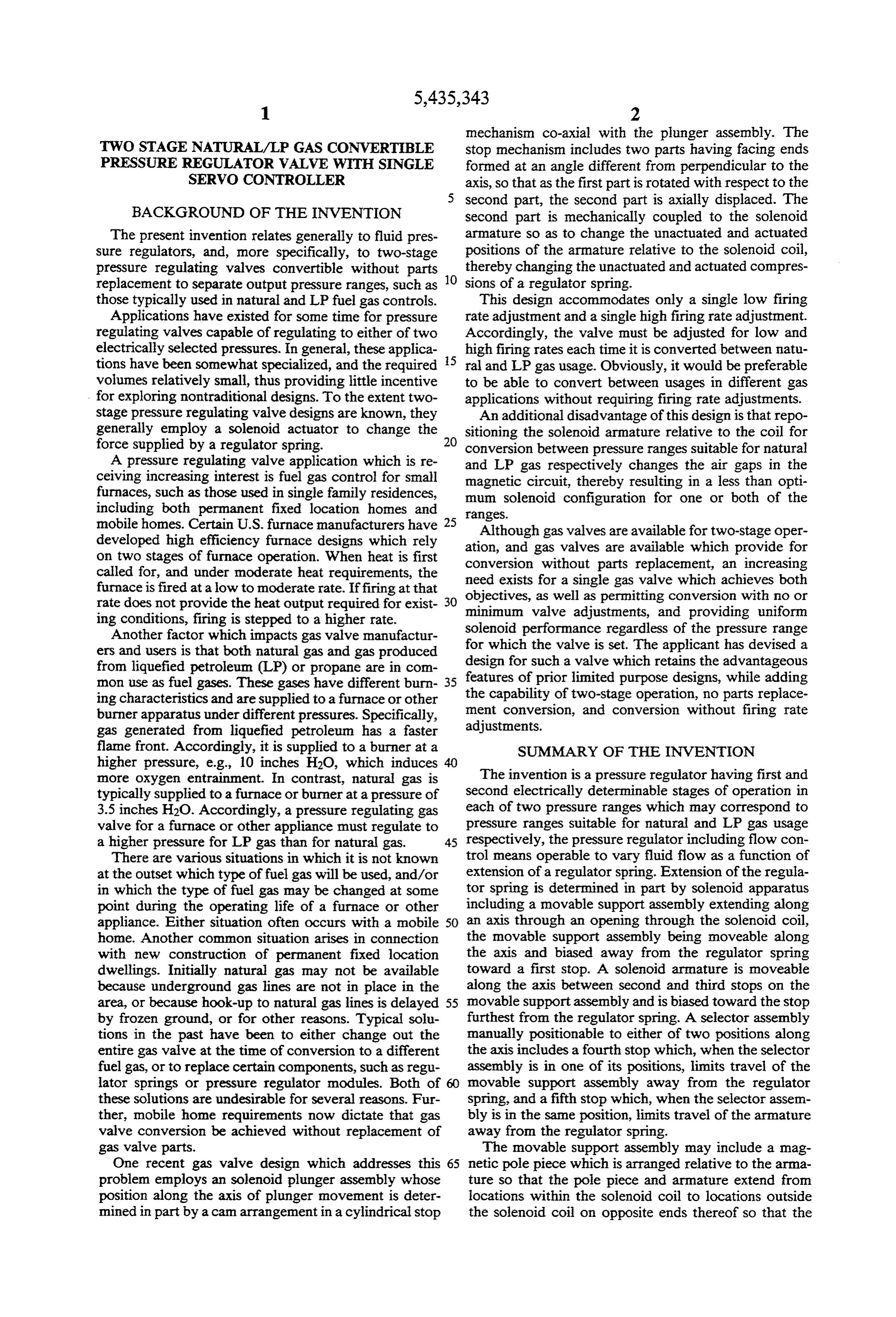
assembly extending from the pressure regulator hous Main valve 17 includes a valve closure member 22 ling. carried on a diaphragm actuator 23. Closure member 22 The positions of the first stop, the stop on the mov cooperates with a main valve seat 24 to vary the flow of able support assembly furthest from the regulator spring gas between inlet passageway 12 and outlet passageway and the fourth and fifth stops on the selector assembly O 13, provided valves 15 and 16 are open. may be individually adjusted along the axis. Finally, the A pressure chamber 25 is formed between housing 11 regulator spring may be mechanically coupled to the and a first side of diaphragm 23 opposite the side on armature by means of a strut which extends through a which valve seat 24 is located. A compression spring 26 hole through the magnetic pole piece and a guide hole within pressure chamber 25 between housing 11 and the through a plug which attaches the tubular barrel to the 15 first side of diaphragm 23 biases closure member 22 pressure regulator housing. toward valve seat 24 to normally maintain valve 17 in a closed state.
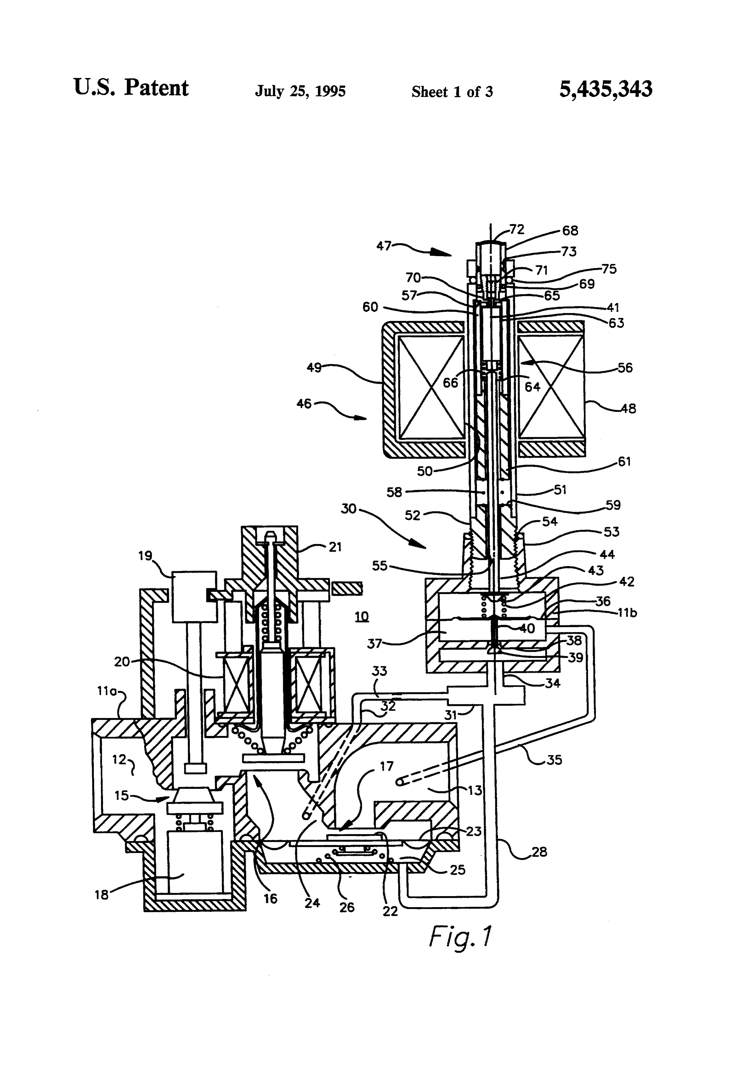
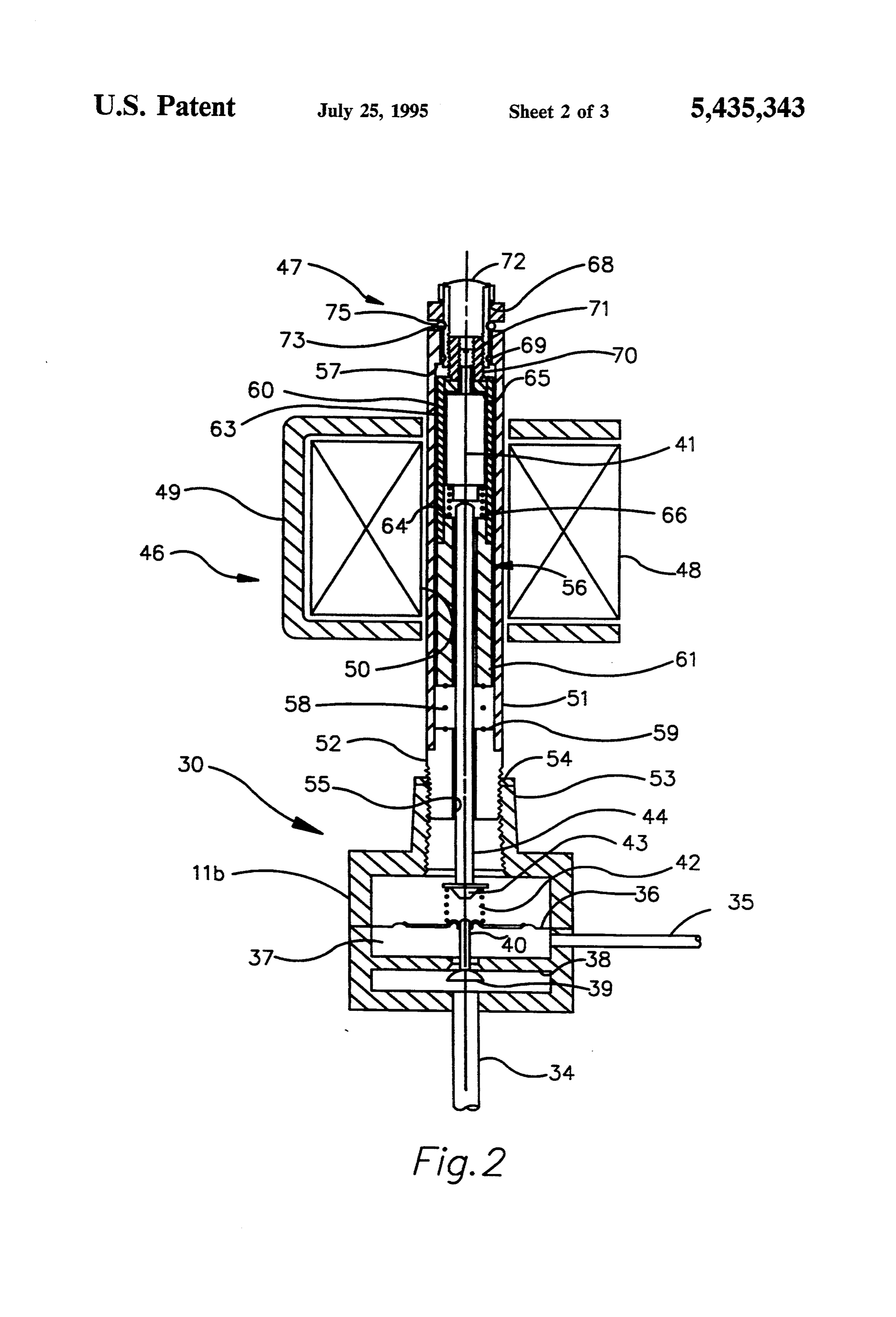
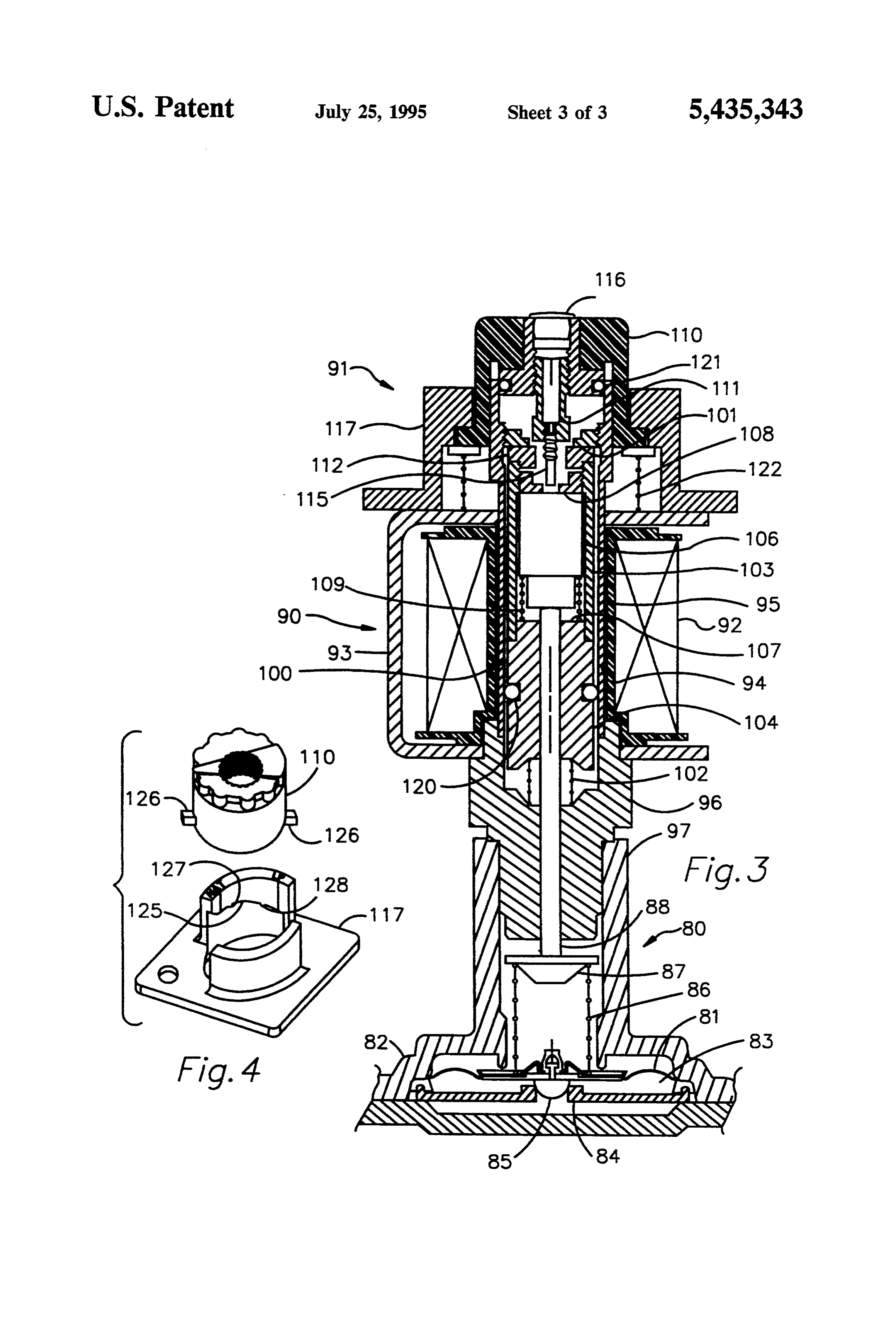
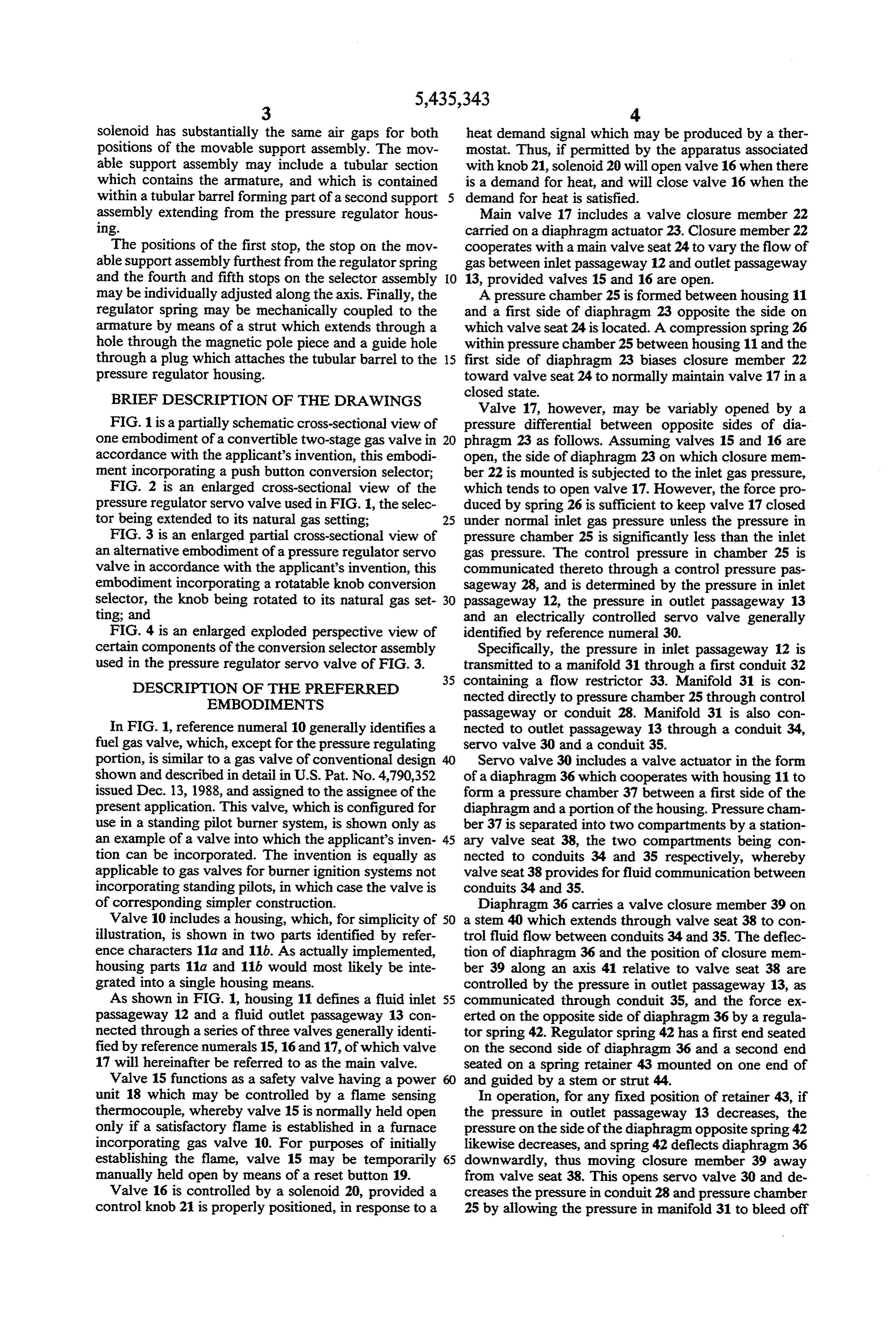
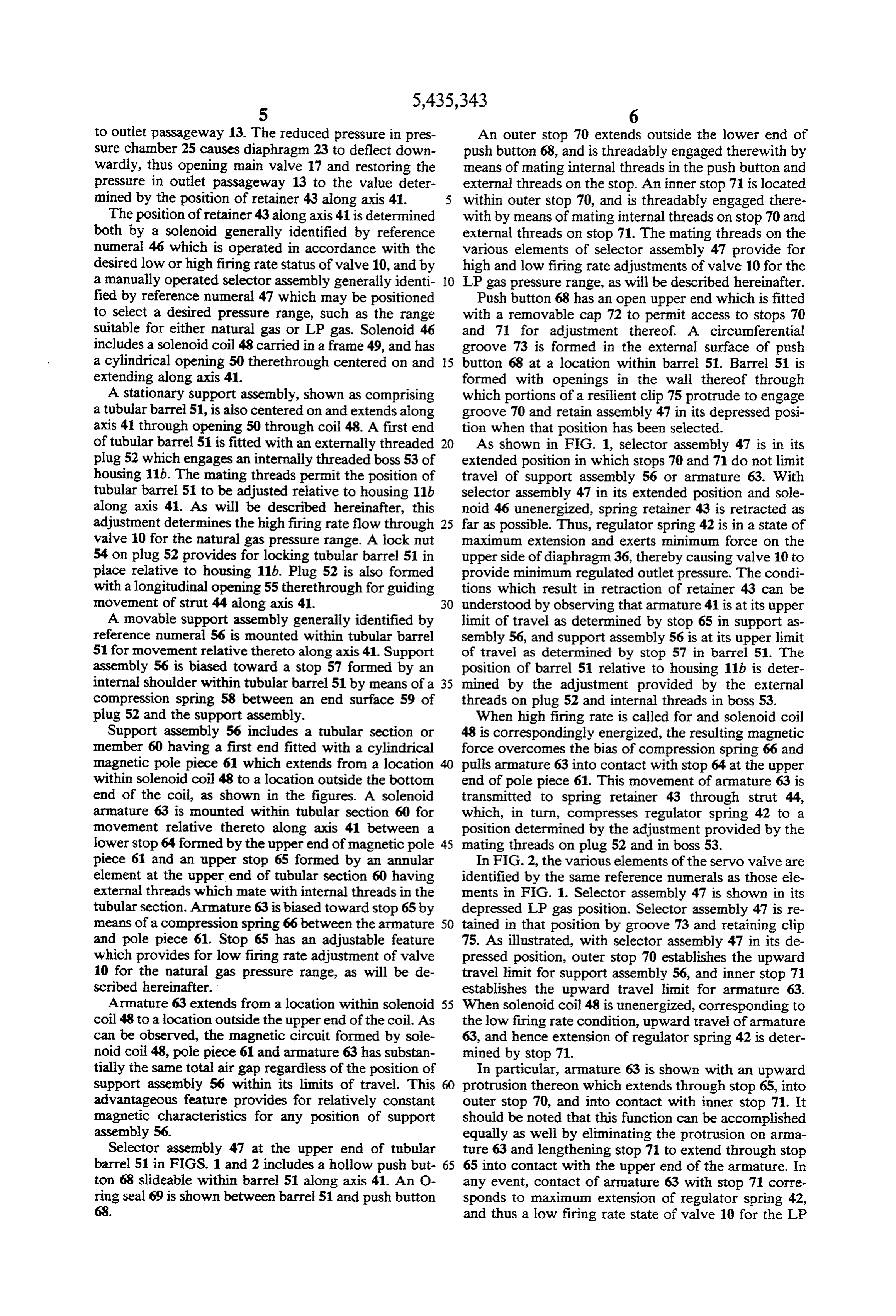
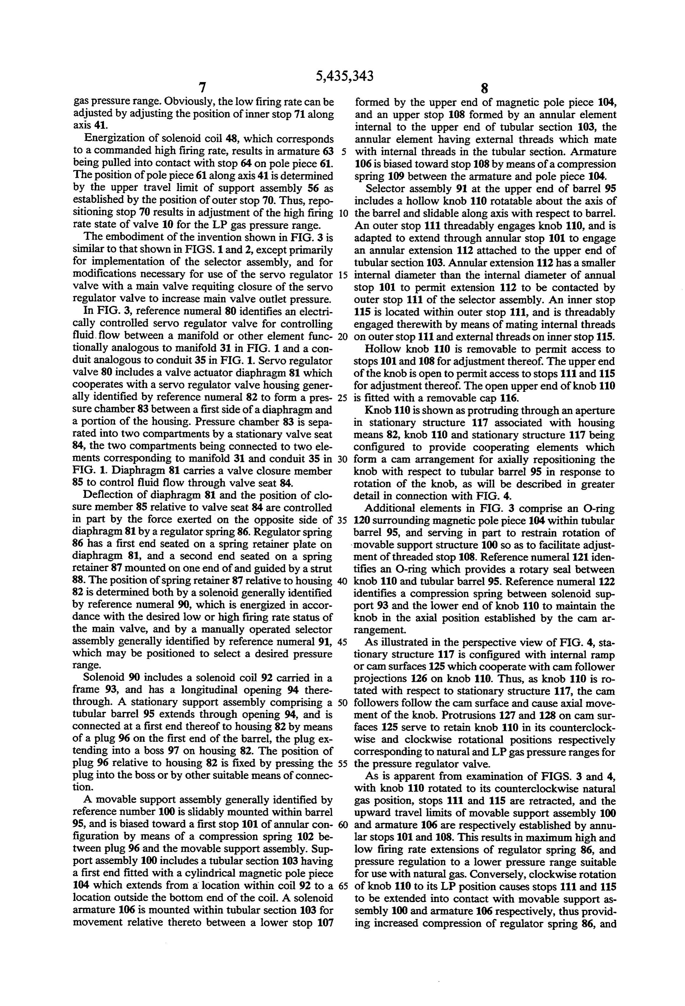
BRIEF DESCRIPTION OF THE DRAWINGS Valve 17, however, may be variably opened by a FIG. 1 is a partially schematic cross-sectional view of pressure differential between opposite sides of dia one embodiment of a convertible two-stage gas valve in 20 phragm 23 as follows. Assuming valves 15 and 16 are accordance with the applicant's invention, this embodi open, the side of diaphragm 23 on which closure mem ment incorporating a push button conversion selector; ber 22 is mounted is subjected to the inlet gas pressure, FIG. 2 is an enlarged cross-sectional view of the which tends to open valve 17. However, the force pro pressure regulator servo valve used in FIG. 1, the selec duced by spring 26 is sufficient to keep valve 17 closed tor being extended to its natural gas setting; 25 under normal inlet gas pressure unless the pressure in FIG. 3 is an enlarged partial cross-sectional view of pressure chamber 25 is significantly less than the inlet an alternative embodiment of a pressure regulator servo gas pressure. The control pressure in chamber 25 is valve in accordance with the applicant's invention, this communicated thereto through a control pressure pas embodiment incorporating a rotatable knob conversion sageway 28, and is determined by the pressure in inlet selector, the knob being rotated to its natural gas set- 30 passageway 12, the pressure in outlet passageway 13 ting; and and an electrically controlled servo valve generally FIG. 4 is an enlarged exploded perspective view of identified by reference numeral 30.
certain components of the conversion selector assembly Specifically, the pressure in inlet passageway 12 is used in the pressure regulator servo valve of FIG. 3. transmitted to a manifold 31 through a first conduit 32 35 containing a flow restrictor 33. Manifold 31 is con
DESCRIPTION OF THE PREFERRED
EMBODIMENTS nected directly to pressure chamber 25 through control passageway or conduit 28. Manifold 31 is also con
In FIG. 1, reference numeral 10 generally identifies a nected to outlet passageway 13 through a conduit 34, fuel gas valve, which, except for the pressure regulating servo valve 30 and a conduit 35. portion, is similar to a gas valve of conventional design Servo valve 30 includes a valve actuator in the form shown and described in detail in U.S. Pat. No. 4,790,352 of a diaphragm 36 which cooperates with housing 11 to issued Dec. 13, 1988, and assigned to the assignee of the form a pressure chamber 37 between a first side of the present application. This valve, which is configured for diaphragm and a portion of the housing. Pressure cham use in a standing pilot burner system, is shown only as ber 37 is separated into two compartments by a station an example of a valve into which the applicant's inven 45 ary valve seat 38, the two compartments being con tion can be incorporated. The invention is equally as nected to conduits 34 and 35 respectively, whereby applicable to gas valves for burner ignition systems not valve seat 38 provides for fluid communication between incorporating standing pilots, in which case the valve is conduits 34 and 35.
of corresponding simpler construction. Diaphragm 36 carries a valve closure member 39 on Valve 10 includes a housing, which, for simplicity of 50 a stem 40 which extends through valve seat 38 to con illustration, is shown in two parts identified by refer trol fluid flow between conduits 34 and 35. The deflec ence characters 11a and 11b. As actually implemented, tion of diaphragm 36 and the position of closure mem housing parts 11a and 11b would most likely be inte ber 39 along an axis 41 relative to valve seat 38 are grated into a single housing means. controlled by the pressure in outlet passageway 13, as As shown in FIG. 1, housing 11 defines a fluid inlet 55 communicated through conduit 35, and the force ex passageway 12 and a fluid outlet passageway 13 con erted on the opposite side of diaphragm 36 by a regula nected through a series of three valves generally identi tor spring 42. Regulator spring 42 has a first end seated fied by reference numerals 15, 16 and 17, of which valve on the second side of diaphragm 36 and a second end 17 will hereinafter be referred to as the main valve. seated on a spring retainer 43 mounted on one end of Valve 15 functions as a safety valve having a power and guided by a stem or strut 44.
unit 18 which may be controlled by a flame sensing In operation, for any fixed position of retainer 43, if thermocouple, whereby valve 15 is normally held open the pressure in outlet passageway 13 decreases, the only if a satisfactory flame is established in a furnace pressure on the side of the diaphragm opposite spring 42 incorporating gas valve 10. For purposes of initially likewise decreases, and spring 42 deflects diaphragm 36 establishing the flame, valve 15 may be temporarily 65 downwardly, thus moving closure member 39 away manually held open by means of a reset button 19. from valve seat 38. This opens servo valve 30 and de Valve 16 is controlled by a solenoid 20, provided a creases the pressure in conduit 28 and pressure chamber control knob 21 is properly positioned, in response to a 25 by allowing the pressure in manifold 31 to bleed off
Page 7
to outlet passageway 13. The reduced pressure in pres An outer stop 70 extends outside the lower end of sure chamber 25 causes diaphragm 23 to deflect down push button 68, and is threadably engaged therewith by wardly, thus opening main valve 17 and restoring the means of mating internal threads in the push button and pressure in outlet passageway 13 to the value deter external threads on the stop. An inner stop 71 is located mined by the position of retainer 43 along axis 41. within outer stop 70, and is threadably engaged there The position of retainer 43 along axis 41 is determined with by means of mating internal threads on stop 70 and both by a solenoid generally identified by reference external threads on stop 71. The mating threads on the numeral 46 which is operated in accordance with the various elements of selector assembly 47 provide for desired low or high firing rate status of valve 10, and by high and low firing rate adjustments of valve 10 for the a manually operated selector assembly generally identi O LP gas pressure range, as will be described hereinafter. fied by reference numeral 47 which may be positioned Push button 68 has an open upper end which is fitted to select a desired pressure range, such as the range with a removable cap 72 to permit access to stops 70 suitable for either natural gas or LP gas. Solenoid 46 and 71 for adjustment thereof. A circumferential includes a solenoid coil 48 carried in a frame 49, and has groove 73 is formed in the external surface of push a cylindrical opening 50 therethrough centered on and 15 button 68 at a location within barrel 51. Barrel 51 is extending along axis 41. formed with openings in the wall thereof through A stationary support assembly, shown as comprising which portions of a resilient clip 75 protrude to engage a tubular barrel 51, is also centered on and extends along groove 70 and retain assembly 47 in its depressed posi axis 41 through opening 50 through coil 48. A first end tion when that position has been selected. of tubular barrel 51 is fitted with an externally threaded 20 As shown in FIG. 1, selector assembly 47 is in its plug 52 which engages an internally threaded boss 53 of extended position in which stops 70 and 71 do not limit housing 11b. The mating threads permit the position of travel of support assembly 56 or armature 63. With tubular barrel 51 to be adjusted relative to housing 11b selector assembly 47 in its extended position and sole along axis 41. As will be described hereinafter, this noid 46 unenergized, spring retainer 43 is retracted as adjustment determines the high firing rate flow through 25 far as possible. Thus, regulator spring 42 is in a state of valve 10 for the natural gas pressure range. A lock nut maximum extension and exerts minimum force on the 54 on plug 52 provides for locking tubular barrel 51 in upper side of diaphragm36, thereby causing valve 10 to place relative to housing 11b. Plug 52 is also formed provide minimum regulated outlet pressure. The condi with a longitudinal opening 55therethrough for guiding tions which result in retraction of retainer 43 can be movement of strut 44 along axis 41. 30 understood by observing that armature 41 is at its upper A movable support assembly generally identified by limit of travel as determined by stop 65 in support as reference numeral 56 is mounted within tubular barrel sembly 56, and support assembly 56 is at its upper limit 51 for movement relative thereto along axis 41. Support of travel as determined by stop 57 in barrel 51. The assembly 56 is biased toward a stop 57 formed by an position of barrel 51 relative to housing 11b is deter internal shoulder within tubular barrel 51 by means of a 35 mined by the adjustment provided by the external compression spring 58 between an end surface 59 of threads on plug 52 and internal threads in boss 53. plug 52 and the support assembly. When high firing rate is called for and solenoid coil Support assembly 56 includes a tubular section or 48 is correspondingly energized, the resulting magnetic member 60 having a first end fitted with a cylindrical force overcomes the bias of compression spring 66 and magnetic pole piece 61 which extends from a location pulls armature 63 into contact with stop 64 at the upper within solenoid coil 48 to a location outside the botton end of pole piece 61. This movement of armature 63 is end of the coil, as shown in the figures. A solenoid transmitted to spring retainer 43 through strut 44, armature 63 is mounted within tubular section 60 for which, in turn, compresses regulator spring 42 to a movement relative thereto along axis 41 between a position determined by the adjustment provided by the lower stop 64 formed by the upper end of magnetic pole 45 mating threads on plug 52 and in boss 53. piece 61 and an upper stop 65 formed by an annular In FIG. 2, the various elements of the servo valve are element at the upper end of tubular section 60 having identified by the same reference numerals as those ele external threads which mate with internal threads in the ments in FIG. 1. Selector assembly 47 is shown in its tubular section. Armature 63 is biased toward stop 65 by depressed LP gas position. Selector assembly 47 is re means of a compression spring 66 between the armature 50 tained in that position by groove 73 and retaining clip and pole piece 61. Stop 65 has an adjustable feature 75. As illustrated, with selector assembly 47 in its de which provides for low firing rate adjustment of valve pressed position, outer stop 70 establishes the upward 10 for the natural gas pressure range, as will be de travel limit for support assembly 56, and inner stop 71 scribed hereinafter. establishes the upward travel limit for armature 63. Armature 63 extends from a location within solenoid 55 When solenoid coil 48 is unenergized, corresponding to coil 48 to a location outside the upper end of the coil. As the low firing rate condition, upward travel of armature can be observed, the magnetic circuit formed by sole 63, and hence extension of regulator spring 42 is deter noid coil 48, pole piece 61 and armature 63 has substan mined by stop 71.
tially the same total air gap regardless of the position of In particular, armature 63 is shown with an upward support assembly 56 within its limits of travel. This 60 protrusion thereon which extends through stop 65, into advantageous feature provides for relatively constant outer stop 70, and into contact with inner stop 71. It magnetic characteristics for any position of support should be noted that this function can be accomplished assembly 56. equally as well by eliminating the protrusion on arma Selector assembly 47 at the upper end of tubular ture 63 and lengthening stop 71 to extend through stop barrel 51 in FIGS. 1 and 2 includes a hollow push but 65 65 into contact with the upper end of the armature. In ton 68 slideable within barrel 51 along axis 41. An O any event, contact of armature 63 with stop 71 corre ring seal 69 is shown between barrel 51 and push button sponds to maximum extension of regulator spring 42, 68. and thus a low firing rate state of valve 10 for the LP
Page 8
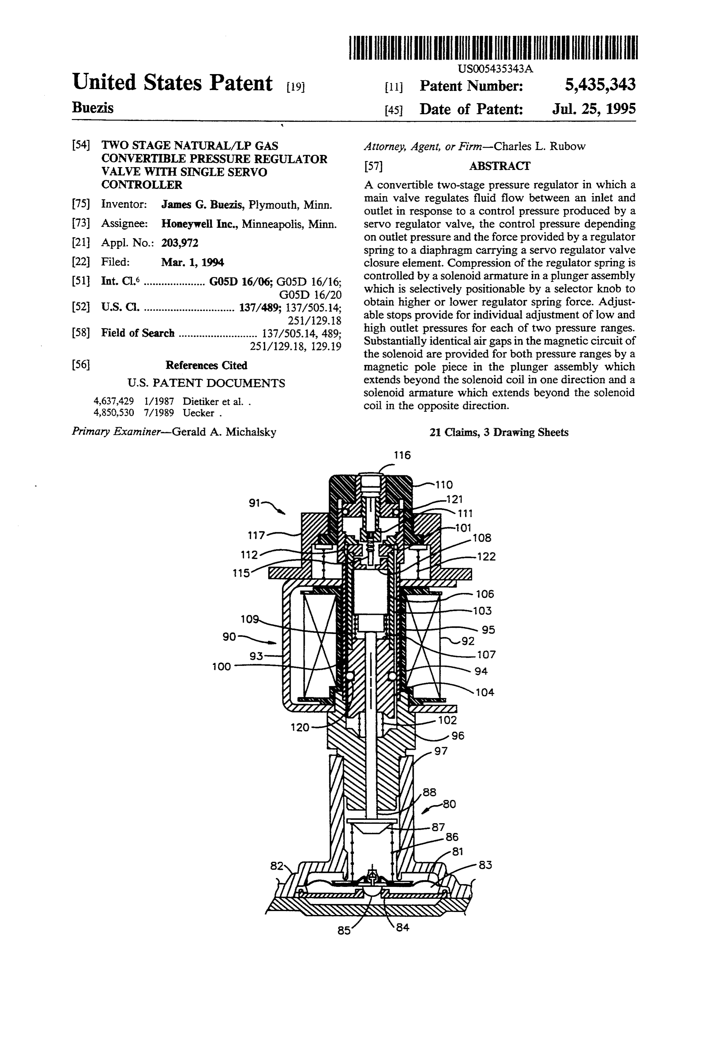
gas pressure range. Obviously, the low firing rate can be formed by the upper end of magnetic pole piece 104, adjusted by adjusting the position of inner stop 71 along and an upper stop 108 formed by an annular element axis 41. internal to the upper end of tubular section 103, the Energization of solenoid coil 48, which corresponds annular element having external threads which mate to a commanded high firing rate, results in armature 63 with internal threads in the tubular section. Armature being pulled into contact with stop 64 on pole piece 61. 106 is biased toward stop 108 by means of a compression The position of pole piece 61 along axis 41 is determined spring 109 between the armature and pole piece 104. by the upper travel limit of support assembly 56 as Selector assembly 91 at the upper end of barrel 95 established by the position of outer stop 70. Thus, repo includes a hollow knob 110 rotatable about the axis of sitioning stop 70 results in adjustment of the high firing O the barrel and slidable along axis with respect to barrel. rate state of valve 10 for the LP gas pressure range. An outer stop 111 threadably engages knob 110, and is The embodiment of the invention shown in FIG. 3 is adapted to extend through annular stop 101 to engage similar to that shown in FIGS. 1 and 2, except primarily an annular extension 112 attached to the upper end of for implementation of the selector assembly, and for tubular section 103. Annular extension 112 has a smaller modifications necessary for use of the servo regulator 15 internal diameter than the internal diameter of annual valve with a main valve requiting closure of the servo stop 101 to permit extension 112 to be contacted by regulator valve to increase main valve outlet pressure. outer stop 111 of the selector assembly. An inner stop In FIG. 3, reference numeral 80 identifies an electri 115 is located within outer stop 111, and is threadably cally controlled servo regulator valve for controlling engaged therewith by means of mating internal threads fluid flow between a manifold or other element func 20 on outer stop 111 and external threads on inner stop 115. tionally analogous to manifold 31 in FIG. 1 and a con Hollow knob 110 is removable to permit access to duit analogous to conduit 35 in FIG. 1. Servo regulator stops 101 and 108 for adjustment thereof. The upper end valve 80 includes a valve actuator diaphragm 81 which of the knob is open to permit access to stops 111 and 115 cooperates with a servo regulator valve housing gener for adjustment thereof. The open upper end of knob 110 ally identified by reference numeral 82 to form a pres 25 is fitted with a removable cap 116. sure chamber 83 between a first side of a diaphragm and Knob 110 is shown as protruding through an aperture a portion of the housing. Pressure chamber 83 is sepa in stationary structure 117 associated with housing rated into two compartments by a stationary valve seat means 82, knob 110 and stationary structure 117 being 84, the two compartments being connected to two ele configured to provide cooperating elements which ments corresponding to manifold 31 and conduit 35 in 30 form a cam arrangement for axially repositioning the FIG. 1. Diaphragm 81 carries a valve closure member knob with respect to tubular barrel 95 in response to 85 to control fluid flow through valve seat 84. rotation of the knob, as will be described in greater Deflection of diaphragm 81 and the position of clo detail in connection with FIG. 4.
sure member 85 relative to valve seat 84 are controlled Additional elements in FIG. 3 comprise an O-ring in part by the force exerted on the opposite side of 35 120 surrounding magnetic pole piece 104 within tubular diaphragm 81 by a regulator spring 86. Regulator spring barrel 95, and serving in part to restrain rotation of 86 has a first end seated on a spring retainer plate on 'movable support structure 100 so as to facilitate adjust diaphragm 81, and a second end seated on a spring ment of threaded stop 108. Reference numeral 121 iden retainer 87 mounted on one end of and guided by a strut tifies an O-ring which provides a rotary seal between 88. The position of spring retainer 87 relative to housing 40 knob 110 and tubular barrel 95. Reference numeral 122 82 is determined both by a solenoid generally identified identifies a compression spring between solenoid sup by reference numeral 90, which is energized in accor port 93 and the lower end of knob 110 to maintain the dance with the desired low or high firing rate status of knob in the axial position established by the cam ar the main valve, and by a manually operated selector rangement.
assembly generally identified by reference numeral 91, 45 As illustrated in the perspective view of FIG. 4, sta which may be positioned to select a desired pressure tionary structure 117 is configured with internal ramp range. or cam surfaces 125 which cooperate with cam follower Solenoid 90 includes a solenoid coil 92 carried in a projections 126 on knob 110. Thus, as knob 110 is ro frame 93, and has a longitudinal opening 94 there tated with respect to stationary structure 117, the cam through. A stationary support assembly comprising a 50 followers follow the cam surface and cause axial move tubular barrel 95 extends through opening 94, and is ment of the knob. Protrusions 127 and 128 on cam sur connected at a first end thereof to housing 82 by means faces 125 serve to retain knob 110 in its counterclock of a plug 96 on the first end of the barrel, the plug ex wise and clockwise rotational positions respectively tending into a boss 97 on housing 82. The position of corresponding to natural and LP gas pressure ranges for plug 96 relative to housing 82 is fixed by pressing the 55 the pressure regulator valve.
plug into the boss or by other suitable means of connec As is apparent from examination of FIGS. 3 and 4, tion. with knob 110 rotated to its counterclockwise natural A movable support assembly generally identified by gas position, stops 111 and 115 are retracted, and the reference number 100 is slidably mounted within barrel upward travel limits of movable support assembly 100 95, and is biased toward a first stop 101 of annular con and armature 106 are respectively established by annu figuration by means of a compression spring 102 be lar stops 101 and 108. This results in maximum high and tween plug 96 and the movable support assembly. Sup low firing rate extensions of regulator spring 86, and port assembly 100 includes a tubular section 103 having pressure regulation to a lower pressure range suitable a first end fitted with a cylindrical magnetic pole piece for use with natural gas. Conversely, clockwise rotation 104 which extends from a location within coil 92 to a 65 of knob 110 to its LP position causes stops 111 and 115 location outside the bottom end of the coil. A solenoid to be extended into contact with movable support as armature 106 is mounted within tubular section 103 for sembly 100 and armature 106 respectively, thus provid movement relative thereto between a lower stop 107 ing increased compression of regulator spring 86, and
Page 9
pressure regulation to a higher pressure range for use movement therein, and carrying said selector as with LP gas. v sembly thereon.
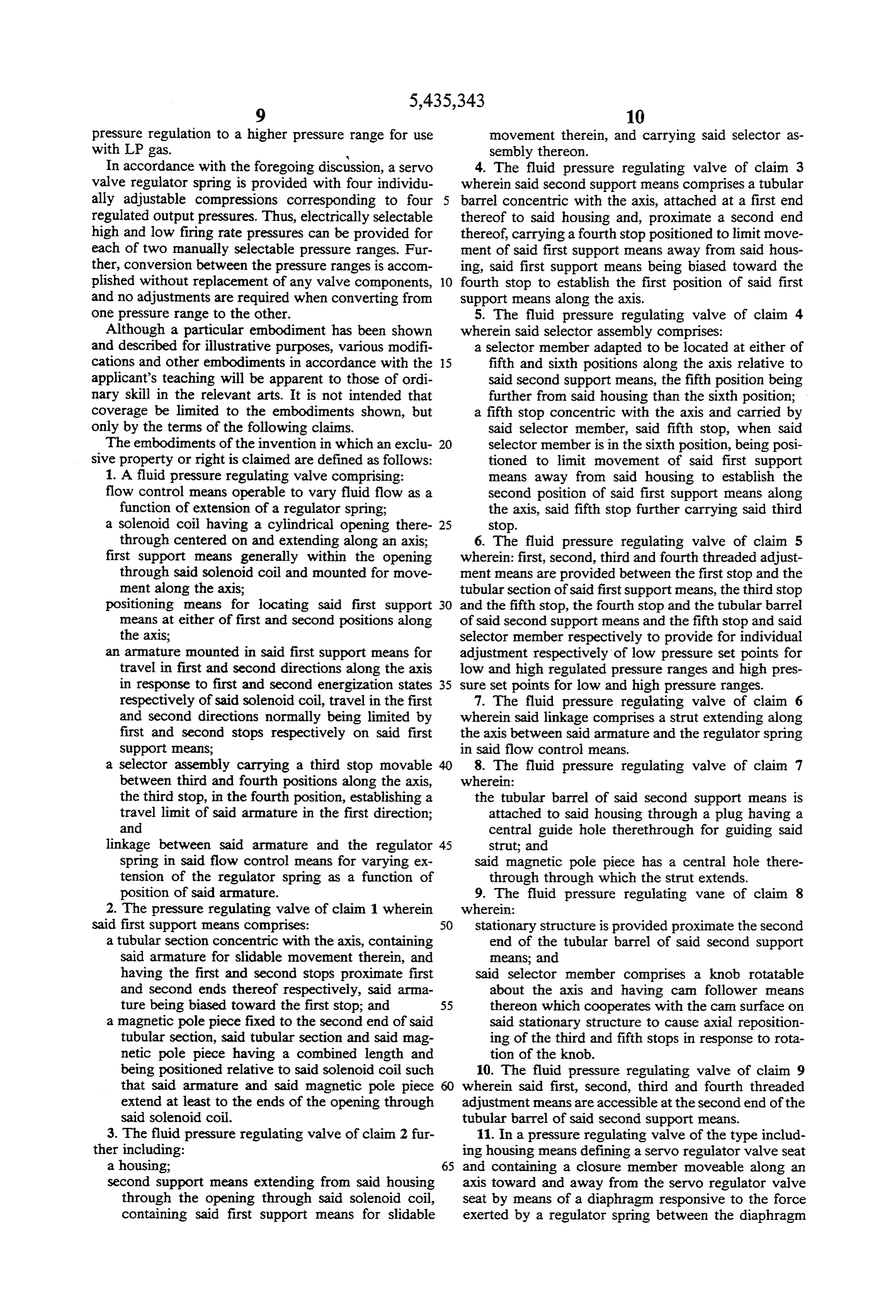
In accordance with the foregoing discussion, a servo 4. The fluid pressure regulating valve of claim 3 valve regulator spring is provided with four individu wherein said second support means comprises a tubular ally adjustable compressions corresponding to four barrel concentric with the axis, attached at a first end regulated output pressures. Thus, electrically selectable thereof to said housing and, proximate a second end high and low firing rate pressures can be provided for thereof, carrying a fourth stop positioned to limit move each of two manually selectable pressure ranges. Fur ment of said first support means away from said hous ther, conversion between the pressure ranges is accom ing, said first support means being biased toward the plished without replacement of any valve components, O fourth stop to establish the first position of said first and no adjustments are required when converting from support means along the axis.
one pressure range to the other. 5. The fluid pressure regulating valve of claim 4 Although a particular embodiment has been shown wherein said selector assembly comprises: and described for illustrative purposes, various modifi a selector member adapted to be located at either of cations and other embodiments in accordance with the 5 fifth and sixth positions along the axis relative to applicant's teaching will be apparent to those of ordi said second support means, the fifth position being nary skill in the relevant arts. It is not intended that further from said housing than the sixth position; coverage be limited to the embodiments shown, but a fifth stop concentric with the axis and carried by only by the terms of the following claims. said selector member, said fifth stop, when said The embodiments of the invention in which an exclu 20 selector member is in the sixth position, being posi sive property or right is claimed are defined as follows: tioned to limit movement of said first support 1. A fluid pressure regulating valve comprising: means away from said housing to establish the flow control means operable to vary fluid flow as a second position of said first support means along function of extension of a regulator spring; the axis, said fifth stop further carrying said third a solenoid coil having a cylindrical opening there 25 stop.
through centered on and extending along an axis; 6. The fluid pressure regulating valve of claim 5 first support means generally within the opening wherein: first, second, third and fourth threaded adjust through said solenoid coil and mounted for move ment means are provided between the first stop and the ment along the axis; tubular section of said first support means, the third stop positioning means for locating said first support 30 and the fifth stop, the fourth stop and the tubular barrel means at either of first and second positions along of said second support means and the fifth stop and said the axis; selector member respectively to provide for individual an armature mounted in said first support means for adjustment respectively of low pressure set points for travel in first and second directions along the axis low and high regulated pressure ranges and high pres in response to first and second energization states 35 sure set points for low and high pressure ranges. respectively of said solenoid coil, travel in the first 7. The fluid pressure regulating valve of claim 6 and second directions normally being limited by wherein said linkage comprises a strut extending along first and second stops respectively on said first the axis between said armature and the regulator spring support means; in said flow control means.
a selector assembly carrying a third stop movable 8. The fluid pressure regulating valve of claim 7 between third and fourth positions along the axis, wherein:
the third stop, in the fourth position, establishing a the tubular barrel of said second support means is travel limit of said armature in the first direction; attached to said housing through a plug having a and central guide hole therethrough for guiding said linkage between said armature and the regulator 45 strut; and spring in said flow control means for varying ex said magnetic pole piece has a central hole there tension of the regulator spring as a function of through through which the strut extends. position of said armature. 9. The fluid pressure regulating vane of claim 8 2. The pressure regulating valve of claim 1 wherein wherein:
said first support means comprises: stationary structure is provided proximate the second a tubular section concentric with the axis, containing end of the tubular barrel of said second support said armature for slidable movement therein, and means; and having the first and second stops proximate first said selector member comprises a knob rotatable and second ends thereof respectively, said arma about the axis and having cam follower means ture being biased toward the first stop; and 55 thereon which cooperates with the can surface on a magnetic pole piece fixed to the second end of said said stationary structure to cause axial reposition tubular section, said tubular section and said mag ing of the third and fifth stops in response to rota netic pole piece having a combined length and tion of the knob.
being positioned relative to said solenoid coil such 10. The fluid pressure regulating valve of claim 9 that said armature and said magnetic pole piece wherein said first, second, third and fourth threaded extend at least to the ends of the opening through adjustment means are accessible at the second end of the said solenoid coil. tubular barrel of said second support means. 3. The fluid pressure regulating valve of claim 2 fur 11. In a pressure regulating valve of the type includ ther including: ing housing means defining a servo regulator valve seat a housing; 65 and containing a closure member moveable along an second support means extending from said housing axis toward and away from the servo regulator valve through the opening through said solenoid coil, seat by means of a diaphragm responsive to the force containing said first support means for slidable exerted by a regulator spring between the diaphragm
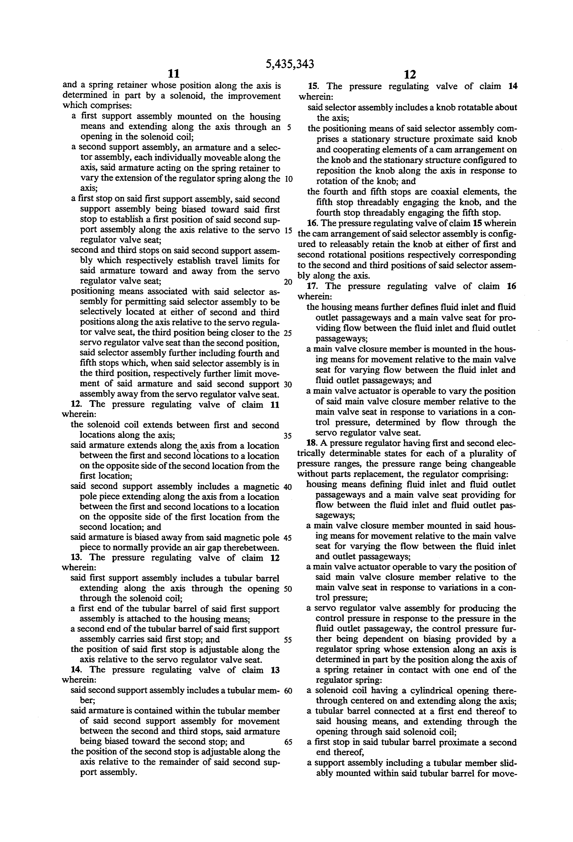
Page 10
and a spring retainer whose position along the axis is 15. The pressure regulating valve of claim 14 determined in part by a solenoid, the improvement wherein:
which comprises: said selector assembly includes a knob rotatable about a first support assembly mounted on the housing the axis;
means and extending along the axis through an the positioning means of said selector assembly com opening in the solenoid coil; prises a stationary structure proximate said knob a second Support assembly, an armature and a selec and cooperating elements of a can arrangement on tor assembly, each individually moveable along the the knob and the stationary structure configured to axis, said armature acting on the spring retainer to reposition the knob along the axis in response to vary the extension of the regulator spring along the O rotation of the knob; and aXIS; the fourth and fifth stops are coaxial elements, the a first stop on said first support assembly, said second fifth stop threadably engaging the knob, and the Support assembly being biased toward said first fourth stop threadably engaging the fifth stop. Stop to establish a first position of said second sup 16. The pressure regulating valve of claim 15 wherein port assembly along the axis relative to the servo 15 the cam arrangement of said selector assembly is config regulator valve seat; ured to releasably retain the knob at either of first and Second and third stops on said second support assem second rotational positions respectively corresponding bly which respectively establish travel limits for to the second said armature toward and away from the servo bly along the and axis.
third positions of said selector assem
17. The pressure regulating valve of claim 16 positioning means associated with said selector as wherein:
sembly for permitting said selector assembly to be the housing means further defines fluid inlet and fluid Selectively located at either of second and third outlet passageways and a main valve seat for pro positions along the axis relative to the servo regula viding flow between the fluid inlet and fluid outlet tor valve seat, the third position being closer to the 25 passageways;
servo regulator valve seat than the second position, a main valve closure member is mounted in the hous Said selector assembly further including fourth and ing means for movement relative to the main valve fifth stops which, when said selector assembly is in seat for varying flow between the fluid inlet and the third position, respectively further limit move fluid outlet passageways; and ment of said armature and said second support 30 a main valve actuator is operable to vary the position assembly away from the servo regulator valve seat. of said main valve closure member relative to the 12. The pressure regulating valve of claim 11 wherein: main valve seat in response to variations in a con the solenoid coil extends between first and second trol pressure, determined by flow through the locations along the axis; 35 servo regulator valve seat. saidbetween armature extends along the axis from a location 18. A pressure regulator having first and second elec the first and second locations to a location trically determinable states for each of a plurality of on the opposite side of the second location from the pressure ranges, the pressure range being changeable first location; without parts replacement, the regulator comprising: Said second support assembly includes a magnetic housing means defining fluid inlet and fluid outlet pole piece extending along the axis from a location passageways and a main valve seat providing for between the first and second locations to a location flow between the fluid inlet and fluid outlet pas on the opposite side of the first location from the sageways;
Second location; and a main valve closure member mounted in said hous said armature is biased away from said magnetic pole 45 ing means for movement relative to the main valve piece to normally provide an air gap therebetween. seat for varying the flow between the fluid inlet 13. The pressure regulating valve of claim 12 and outlet passageways; wherein: a main valve actuator operable to vary the position of said first support assembly includes a tubular barrel said main valve closure member relative to the extending along the axis through the opening 50 main valve seat in response to variations in a con through the solenoid coil; trol pressure;
a first end of the tubular barrel of said first support a servo regulator valve assembly for producing the assembly is attached to the housing means; control pressure in response to the pressure in the a second end of the tubular barrel of said first support fluid outlet passageway, the control pressure fur assembly carries said first stop; and 55 ther being dependent on biasing provided by a the position of said first stop is adjustable along the regulator spring whose extension along an axis is axis relative to the servo regulator valve seat. determined in part by the position along the axis of 14. The pressure regulating valve of claim 13 a spring retainer in contact with one end of the wherein: regulator spring:
said second support assembly includes a tubular mem a Solenoid coil having a cylindrical opening there ber; through centered on and extending along the axis; said armature is contained within the tubular member a tubular barrel connected at a first end thereof to of said second support assembly for movement said housing means, and extending through the between the second and third stops, said armature opening through said solenoid coil; being biased toward the second stop; and 65 a first stop in said tubular barrel proximate a second the position of the second stop is adjustable along the end thereof, axis relative to the remainder of said second sup a Support assembly including a tubular member slid port assembly. ably mounted within said tubular barrel for move
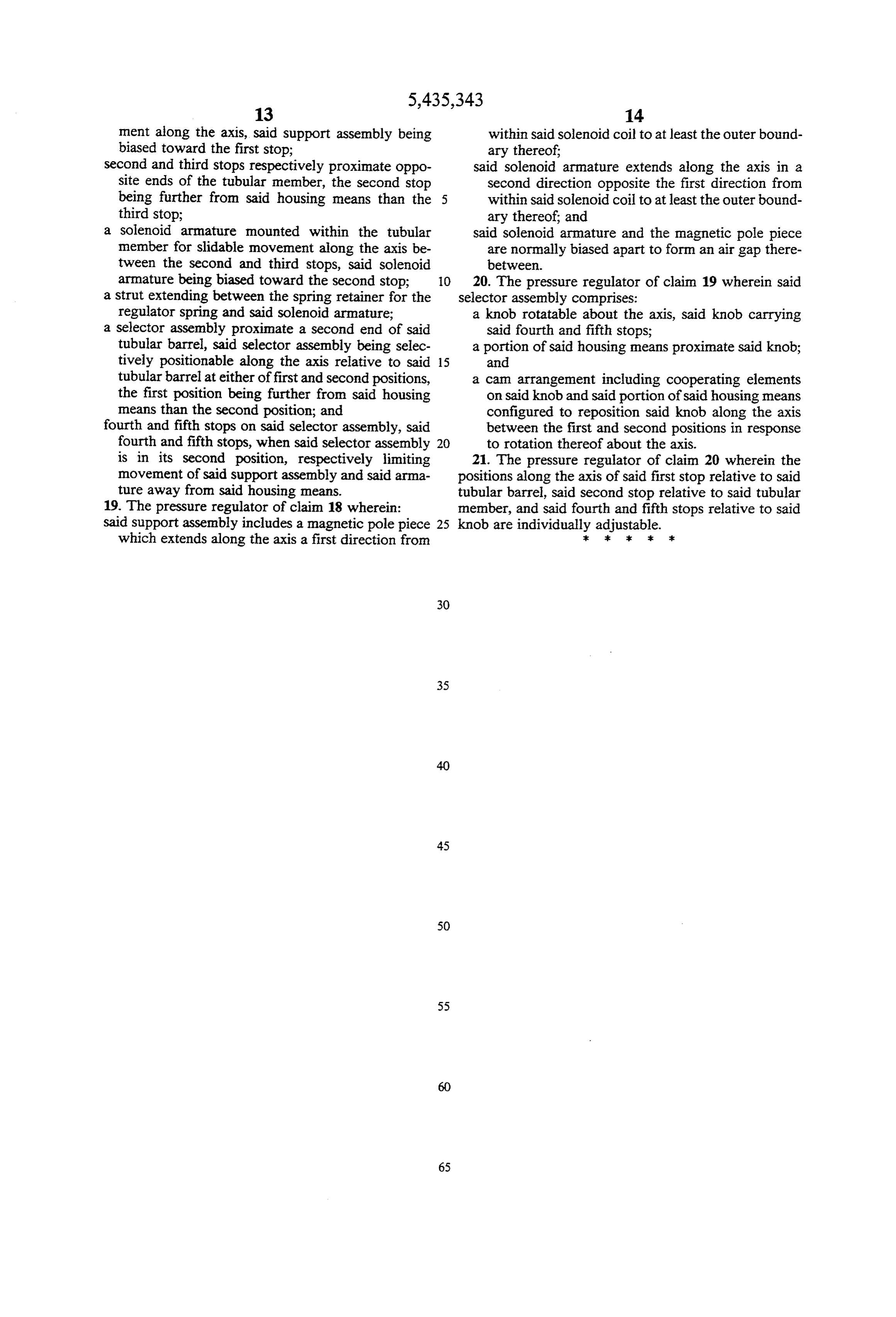
Page 11
ment along the axis, said support assembly being within said solenoid coil to at least the outer bound biased toward the first stop; ary thereof;
Second and third stops respectively proximate oppo said solenoid armature extends along the axis in a site ends of the tubular member, the second stop second direction opposite the first direction from being further from said housing means than the 5 within said solenoid coil to at least the outer bound third stop; ary thereof; and a Solenoid armature mounted within the tubular said solenoid armature and the magnetic pole piece member for slidable movement along the axis be are normally biased apart to form an air gap there tween the second and third stops, said solenoid between.
armature being biased toward the second stop; O 20. The pressure regulator of claim 19 wherein said a strut extending between the spring retainer for the selector assembly comprises:
regulator spring and said solenoid armature; a knob rotatable about the axis, said knob carrying a selector assembly proximate a second end of said said fourth and fifth stops; tubular barrel, said selector assembly being selec a portion of said housing means proximate said knob; tively positionable along the axis relative to said 15 and tubular barrel at either of first and second positions, a cam arrangement including cooperating elements the first position being further from said housing on said knob and said portion of said housing means means than the second position; and configured to reposition said knob along the axis fourth and fifth stops on said selector assembly, said between the first and second positions in response fourth and fifth stops, when said selector assembly 20 to rotation thereof about the axis. is in its second position, respectively limiting 21. The pressure regulator of claim 20 wherein the movement of said support assembly and said arma positions along the axis of said first stop relative to said ture away from said housing means. tubular barrel, said second stop relative to said tubular 19. The pressure regulator of claim 18 wherein: member, and said fourth and fifth stops relative to said said support assembly includes a magnetic pole piece 25 knob are individually adjustable.
which extends along the axis a first direction from :: at Ek Ek :
Page 12
UNITED STATES PATENT AND TRADEMARK OFFICE
CERTIFICATE OF CORRECTION
INVENTOR(S) : James G. Buezis it is certified that error appears in the above-identified patent and that said Letters Patent is hereby Corrected as shown below:
Column 10, line 48, cancel "vane", insert --valve--. .
Signed and Sealed this
Tenth Day of October, 1995
BRUCE LEHMAN
Attesting Officer Commissioner of Patents and Trademarks
Provenance
- Collection
- Cited prior art
- Original PDF
- patentimages.storage.googleapis.com →
- Filed
- 1994-03-01
- Pages
- 12
- Method
- pdftotext (the PDF's own text layer) + pdftoppm 300dpi page scans
- Source
- Google Patents bibliographic record
- Granted
- 1995-07-25
- Inventors
- James G. Buezis; Honeywell Inc
- Transcribed from
- patentimages.storage.googleapis.com →