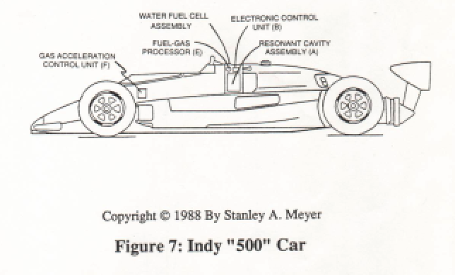
Figure (2)
Figure (2)
How it is written
- (2) 5×
Drawings 41
-
The Fuel-Cell is composed of Resonant Cavities pre-arranged to maximize Fuel-Energy delivery to the car engine, as illustrated in Figure 2 as to Figure 4. · WFC - Resonant Cavity Assembly
-
The Electron Extraction Process (BB) is, hereinafter, called "The GAS RESONANT CAVITY," as illustrated in Figure 1-7 as to Figure 20JX. · Electron Extraction Process
-
The Resonant Frequency (F) of an LC circuit in series is given by (Eq 4) · LC Circuit
-
The Positive Electrical Voltage Field (E3) and Negative Electrical Voltage Fields (E4) are triggered "Simultaneously" during the same duty-pulse. · Electron Extraction Process
-
Toggling action at full-scale deflection (13a xxx 13n) occurs in the range of (10) kHz or above and thus, allows instant response to driver's acceleration demands. · Acceleration Control Circuit (30)
-
Carries this number · WFC 422DA - Illustrations
-
3-8 Multi-Coil Spool · Voltage Intensifier Coil Assembly
-
Carries this number · Voltage Intensifier Coil Assembly
-
Carries this number · Voltage Intensifier Coil Assembly
-
Carries this number · Voltage Intensifier Coil Assembly
-
3-14 WFC Voltage Ignition Wire · Voltage Intensifier Coil Assembly
-
Carries this number · Electronic Circuit Design
-
Carries this number · Electronic Circuit Design
-
Carries this number · Electronic Circuit Design
-
(170) of Figure (13) · Water Fuel Injector (Taper Resonant Cavity Chamber)
-
(170) of Figure (13) · Water Fuel Injector (Taper Resonant Cavity Chamber)
-
Fluid Displacement Pump (170) of Figure (13) · Water Fuel Injector (Taper Resonant Cavity Chamber)
-
(220) of Figure (18) · Water Fuel Injector (Taper Resonant Cavity Chamber)
-
Carries this number · Water Fuel Injector (Taper Resonant Cavity Chamber)
-
The Following Page 1-7 was not available · Water Fuel Injector (Taper Resonant Cavity Chamber)
-
Carries this number · Steam Resonator Assembly
-
Figure (4-8) · Water Fuel Injection System - Page 2
-
(100) of Figure (4-8) · Voltage Intensifier Coil-Assembly
-
"Electron Bounce" phenomenon (700) of Figure (7-9) · Inductance Reactance (Rs - Cd - FL)
-
(100) of Figure (4-8) · Capacitance Reactance
-
Figure (10-3 A/B) · Propagating Electrical Stress
-
(990) of Figure (10-3) · Propagating Electrical Stress
-
The programmable pulse-frequency (49a xxx 49n) of Figure (10-1) input is simply adjusted to tune-in to the dielectric property of the Water Molecule. · Propagating Electrical Stress
-
Carries this number · Voltage to Amp Differential Ratio
-
Figure (10-3A) · Voltage to Amp Differential Ratio
-
Carries this number · WFC 429 - Illustrations
-
Carries this number · WFC 429 - Illustrations
-
Carries this number · WFC 429 - Illustrations
-
Carries this number · WFC 429 - Illustrations
-
Carries this number · Wobbling Effect
-
Carries this number · WFC 430-2 Illustrations
-
dual unipolar voltage pulse circuit (1010) of Figure (11-1) · Voltage Flexing Process
-
(1030) of figure (11-3) · Voltage Flexing Process
-
voltage intensifier circuit (990) of Figure (10-3) · VIC Switchover Circuit
-
(970) of Figure (10-1) · VIC Switchover Circuit
-
Differential Voltage Wave-Guild (1040B) · Electrical Crossover Switching Circuit
On this figure 1
Where it is named · 5
WFC - Resonant Cavity Assembly 2×
-
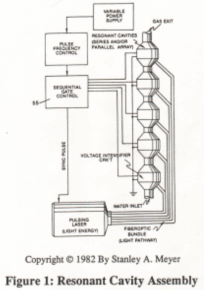
The Water Fuel Cell is a patented process that utilizes an solid-state electronic control system to produce hydrogen gas on demand from water by way of voltage stimulation called "The Electrical Polarization Process", as illustrated in Figure 1 as to Figure 2.
-
The Fuel-Cell is composed of Resonant Cavities pre-arranged to maximize Fuel-Energy delivery to the car engine, as illustrated in Figure 2 as to Figure 4.
Fuel Gas Processor 1×
-
Figure 2: Gas Ionization Chamber
Fuel-Gases / Quenching Tube 2×
-
The liberated and traveling Fuel-Gases enters into ans passed through a patented Fuel-Gas Processor (E) that performs and functions as a Gas Ionization Chamber when another Voltage Intensifier Circuit (A3) is activated by Gas Acceleration Control Unit (B/F), as illustrated in Figure 2 as to Figure 7
-
Figure 2