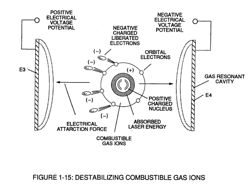
Figure (1-15)
Destabilizing Combustible Gas Ions
Also written Quenching Disc
How it is written
- (1-15) 3×
Drawings 3
-
Figure (1-15) · Electron Extraction Process
-
Quenching Disc Structure (190) of Figure (15) · Water Fuel Injector (Taper Resonant Cavity Chamber)
-
Captioned as this figure · Water Fuel Injection System - Page 3
On this figure 3
Where it is named · 3
Electron Extraction Process 2×
-
Exposing the displaced and moving combustible gas atoms (exiting waterbath and passing through Gas Resonant Cavity (T), Figure (1-17) as to Figure (1-18) to another or separate pulsating laser energy-source (V) at higher voltage levels (E3/E4) causes more electrons to be "pulled away" or "dislodged" from the gas atoms, as illustrated in Figure (1-15) as to Figure (1-8).
-
Figure (1-15)
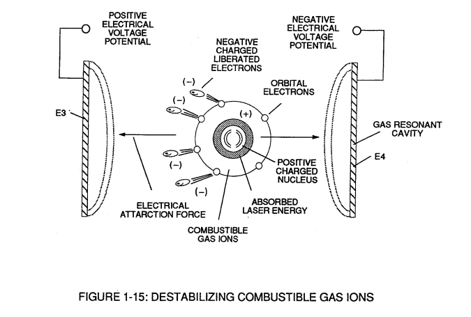
Water Fuel Injection System - Page 3 1×
-
The newly liberated water molecule atoms (oxygen 76 and hydrogen atoms 77a/77b) immediately interact with laser primed ionized ambient air gases (7a xxx 7n of Figure 1-15) (see WFC memo 420) to cause the resultant highly energized and mass destabilized combustible gas atoms (93a xxx 93n) of Figure (4-10) to perform Hydrogen Fracturing Process (80) of Figure (4-9) when …