patent · US6295973
Air-fuel charge controller for a homogeneous-charge, compression-ignition engine
2 October 2001
Page 1 — bibliographic record
(12) United States Patent (10) Patent No.: US 6,295,973 B1 Yang (45) Date of Patent: Oct. 2, 2001
(54) AIR-FUEL CHARGE CONTROLLER FOR A FOREIGN PATENT DOCUMENTS
HOMOGENEOUS-CHARGE, COMPRESSION
IGNITION ENGINE 2936 127 A1 9/1979 (DE).
OTHER PUBLICATIONS
(75) Inventor: Jialin Yang, Canton, MI (US) “Compression -Ignited Homogeneous Charge Combus tion, bv. Paul M. Nait et al. SAE Technical P (73) Assignee: Ford Global Technologies, Inc., S2,4 pp g Cl all, ecnnical Paper No.
Dearborn, MI (US) s * cited by examiner (*) Notice: Subject to any disclaimer, the term of this Primary Examiner Marguerite McMahon patent is extended or adjusted under 35 (74) Attorney, Agent, or Firm Jerome R. Drouillard U.S.C. 154(b) by 0 days. (57) ABSTRACT
No.: 09/470,359 Ainghis charge ESE t engine coolant, an Intake manifold and an exhaust (22) Filed: Dec. 22, 1999 manifold including a controller for advancing and retarding (51) Int. Cl." ................................................. F02M 31/00 auto-ignition in the combustion chamber of the engine, the (52) U.S. Cl. .............................................................. 123/543 intake manifold providing a premixed combustible charge of (58) Field of Search ..................................... 123/543, 544, air and fuel, the intake manifold having dual intake portions, 123/545, 546, 547, 557 one portion Supplying unheated gas, and the other providing s s s gas heated by engine coolant or exhaust gas, or both. A flow (56) References Cited Istributor valve distrib Intake manifold lve in the intak ifold gas fflow passages varies the intake temperature, thereby controlling auto
3,974,808 8/1976 Heitert. combustion chamber during the portion of the combustion 4,167,165 * 9/1979 Finlay et al. ......................... 123,543 cycle in which a homogeneous-charge, compression 4,261,316 * 4/1981 Motosugi et al. ... 123/543 ignition event occurs. The engine includes a Spark ignition 4,395,998 8/1983 Chou .................................... 123/543 System for initiating combustion when the engine load, for 4,494,516 1/1985 Covey, Jr.. a given Speed, increases to a defined level and when the 4,768,481 9/1988 Wood. engine Speed for a given load increases to a defined level.
5,408,973 4/1995 Spangjer. 12 Claims, 5 Drawing Sheets
TOEXHAUST 40 TO RADATOR
EXCHANGER EXCHANGER 18
36 AR N
OXIDATION
CATALYST
PORT PORT 16
OUT
Page 2
Drawing sheet — no readable text.
Page 3
Drawing sheet — no readable text.
Page 4
Drawing sheet — no readable text.
Page 5
EARLY BURN
ROUGH COMBUSTION
s REGION 1 58 HCC REGION MISFIRE, HC, CO
MISFIRE, HC, CO
ENGINE SPEED
0.5 1 OOORPM, PIN=1 BAR, EGR-0% 29.2
EARLY FAST BURN
O. 4 REGION 36.5
DECREASING
CHARGE TEMP
O3 48.7
HCCI REGION
INCREASING
0. 2 CHARGE TEMP 73. O -o-CR 174, GASOLINE HIGHHC, CO d = 0.19
O. 146
INTAKE AIR TEMPERATURE (C)
Page 6
Drawing sheet — no readable text.
Page 7
AIR-FUEL CHARGE CONTROLLER FOR A The limitations of HCCI engines of known design relate HOMOGENEOUS-CHARGE, COMPRESSION to the control of the timing of the auto-ignition event and the IGNITION ENGINE combustion rate for the air-fuel mixture in the combustion chamber. Since combustion begins with auto-ignition of a
TECHNICAL FIELD premixed air-fuel mixture, the ignition may occur at any The invention relates to a controller for the timing of time during the compression process. If the engine load auto-ignition for homogeneous-charge, compression increases, auto-ignition tends to advance and the combustion ignition engines. rate tends to increase due to the rich mixture characteristic of an increased load. Thermal efficiency may decrease due
BACKGROUND OF THE INVENTION to early heat release before top dead center. This results in It is known practice to design four-stroke cycle internal roughness of the engine due to rapid and early combustion. combustion engines to accommodate homogeneous-charge, NO emissions also increase due to increased burnt gas compression-ignition (HCCI) combustion wherein light temperature of the less diluted mixture. When the engine load operation can be achieved with minimal throttling. This 15 load decreases, on the other hand, auto-ignition tends to be results in fuel economy comparable to the fuel economy of retarded, which may result in misfire. a diesel engine of the same displacement. A homogeneous Although it is possible to control auto-ignition by chang charge of fuel and air is used in a HCCI engine in a manner ing the temperature of the air-fuel mixture at the intake Similar to the use of air-fuel mixture in a Spark-ignited manifold using electrical heater devices to promote auto engine, but the homogeneous charge is compressed to auto ignition, Such heaters are impractical for high Volume pro ignition. The homogeneous-charge, compression-ignition duction engines used in the automotive industry. engine thus has characteristics that are comparable in Some BRIEF DESCRIPTION OF THE INVENTION respects to an engine with a diesel cycle.
The temperature of an air-fuel mixture in the combustion It is an objective of the invention to promote efficient chamber of a homogeneous-charge, compression-ignition 25 combustion in a HCCI engine and to control auto-ignition engine (HCCI) is high enough to initiate auto-ignition. The timing by controlling intake air temperature. This objective homogeneous air-fuel mixture is created either in the intake is achieved by using a split air intake System to heat the manifold or in the cylinder by early fuel injection and fast intake air and to adjust the intake air temperature according fuel-air mixing. A homogeneous air-fuel mixture in the to the operating conditions. The temperature adjustment of intake manifold may be achieved, as in the case of a the air-fuel mixture is fast enough to accommodate rapid conventional auto cycle engine, by using a fuel-aspirating changes in engine load.
carburetor or by using a low-pressure fuel injection pump The invention uses hot exhaust gases and engine coolant and nozzle. No spark ignition is necessary when the HCCI as thermal energy Sources for heating the intake air mixture. engine is operating in a specified operating region of the load According to one embodiment of the invention, the heating and engine Speed relationship. 35 of the intake air is controlled by a variable conductance heat It is known design practice also to expand the useful pump wherein thermal energy is transferred from the operating region of the load and engine Speed relationship exhaust port to the intake port.
by using a hybrid ignition controller wherein Spark ignition According to another embodiment of the invention, the can be relied upon during operation at high loads and at high transfer of thermal energy can take place with a rapid engine Speeds with moderate loads. Thus, at lower loads, the 40 response to the intake air-fuel mixture temperature change engine can be operated in HCCI combustion mode with high by using a dual intake System with two intake passages. dilution of the air-fuel mixture using a high air-fuel ratio or When air flows through one passage, it is heated by hot a high exhaust gas recirculation rate in order to limit the rate exhaust gases or engine coolant, or both, using heat of combustion of the homogeneous air-fuel mixture. If the eXchangers. The air or air-fuel mixture in the other passage mixture is too rich, on the other hand, the rate of combustion 45 is unheated. The flow of air in the two passages is mixed at becomes too fast and engine knocking or detonation may the intake port of the cylinder (or cylinders is in the case of OCC. a multiple-cylinder engine). The temperature of the air or the HCCI engines are characterized by minimal variation in mixed air-fuel flow depends on the mass flow rates in the the combustion of the air-fuel mixture since the initiation of two passages, one flow rate being the flow rate for the hot combustion takes place throughout the entire mixture rather 50 gases and the other flow rate being the flow rate for the than at a Single point from which a flame front developS. cooler gases. The relative mass flow rates of the hot and Instabilities of flame propagation are avoided. cooler gases are controlled by a flow distribution valve, or An HCCI engine has reduced levels of nitrous oxide by dual intake valves which can change the gas flow through (NO) in the exhaust gases. This is due to the low combus each of the two passages.
tion temperature of the diluted mixture. It is characterized 55 During operation in the region of the load-speed charac also by reduced Soot or particulates in the emission due to teristic where HCCI combustion occurs, the gases in the the premixed lean mixture. intake manifold pass mainly through the heated passage, The thermal efficiency of an HCCI engine is higher than which results in higher intake air temperatures to promote the thermal efficiency typically associated with Spark igni auto-ignition. Variation in air-flow distribution of the two tion engines of known designs. This is due to the high 60 passages will vary the intake air temperature when the compression ratio that can be used. It is due also to the operating conditions are changed.
unthrottled operation of the air-fuel mixture at the intake When the load of the engine increases, HCCI combustion manifold, which reduces engine pumping losses. High Spe becomes unacceptable because the combustion rate may be cific heat ratios, reduced radiation heat loSS and reduced too high due to the leSS-diluted mixture. The engine then cycle-to-cycle variations in combustion are further charac 65 may operate under high load conditions with a conventional teristics of HCCI engines where combustion does not rely Spark ignition combustion mode. To avoid detonation upon in-cylinder air flow conditions. (knocking) when the engine operates in the Spark ignition
Page 8
combustion mode, the intake air temperature should be as temperature of about 70° C., through passage 24. That low as possible So that the effective compression ratio and heated air is transferred through heat eXchanger 14. This the thermal efficiency can be as high as possible. To reduce increases the temperature of the air before it is delivered to intake air temperature, the heated air passage closes and the heat eXchanger outlet passage 28. The temperature at pas unheated passage opens. sage 28 may be about 200 C.
When the engine load decreases, the combustion mode A portion of the intake air is delivered from mixing point can be Switched back from the Spark ignition mode to the 20 through passage 26 to the mixture point 30. The heated HCCI operating mode. At that time the intake air tempera air in the passage 28 is combined at mixing point 30 with the ture should be boosted to promote auto-ignition. cooler air in passage 26. The combined flow is distributed to To increase air temperature, the heated passage opens, and 1O the engine intake port through passage 32. the unheated passage closes. There is no thermal inertia The engine exhaust gases pass from the engine exhaust involved in this operating Sequence. The response of the port and through exhaust flow passage 34 to a catalytic temperature change of the intake air is fast enough to converter 36. The outlet side of the catalytic converter accommodate rapid changes in engine load. 15 delivers heated exhaust gases in passage 38 to heat eXchanger 14. The exhaust from the heat eXchanger 14
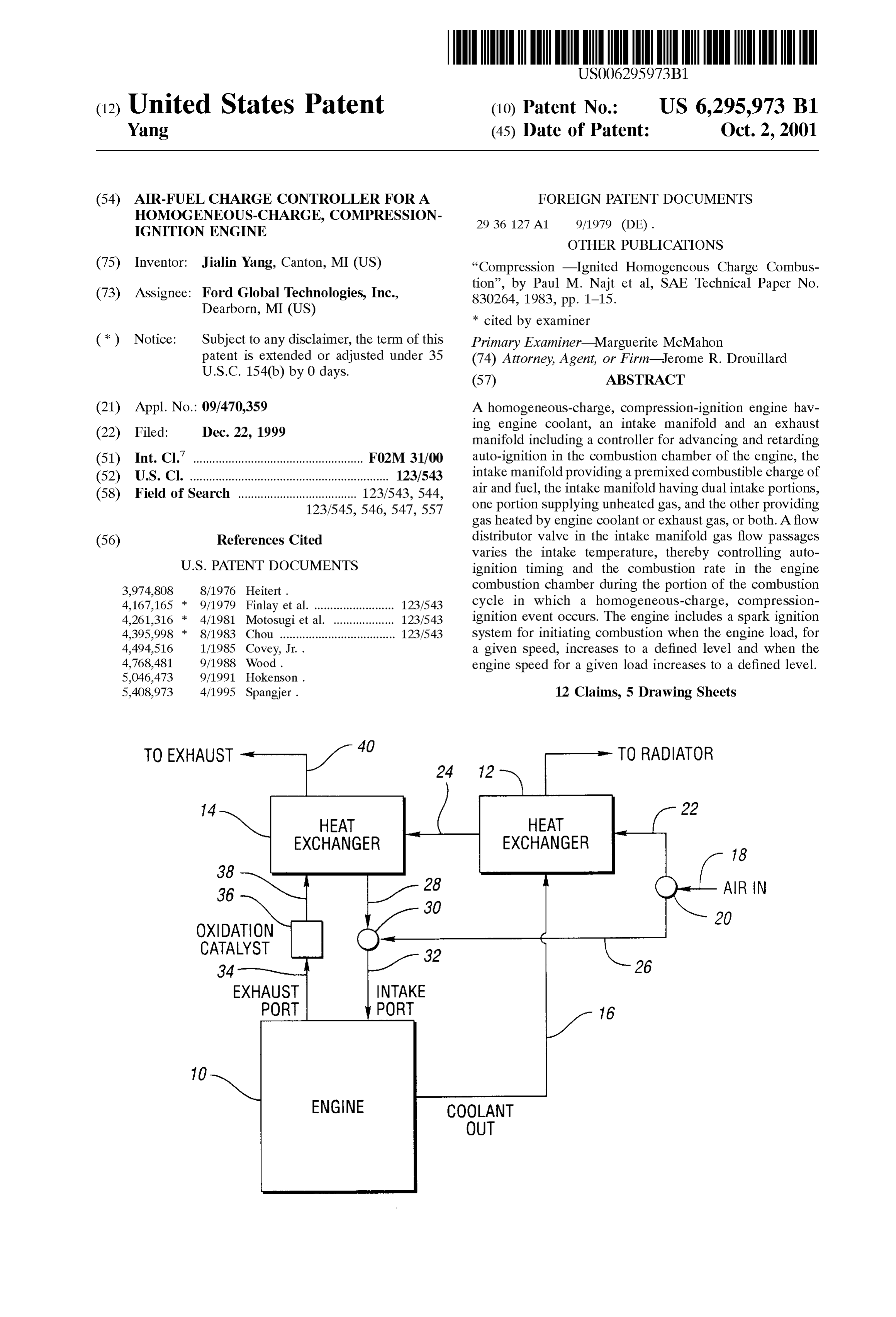
BRIEF DESCRIPTION OF THE DRAWINGS passes through exhaust passage 40. Typically, the tempera FIG. 1 is a schematic block diagram of the split dual ture at the flow inputside of the heat exchanger 14 would be
air-fuel intake system for the HCCI engine of the invention;
FIG. 2 is a detailed Schematic view of the air-fuel mixture The presence of the catalytic converter at 36 between the flow distributor valve in the intake manifold of the HCCI exhaust port and the heat eXchanger 14 will use the boosted temperature level by intake air heating, thereby making engine of the invention; removal of unburned hydrocarbons and carbon monoxide in FIG. 3 is an alternate arrangement of the HCCI system of the exhaust more efficient.
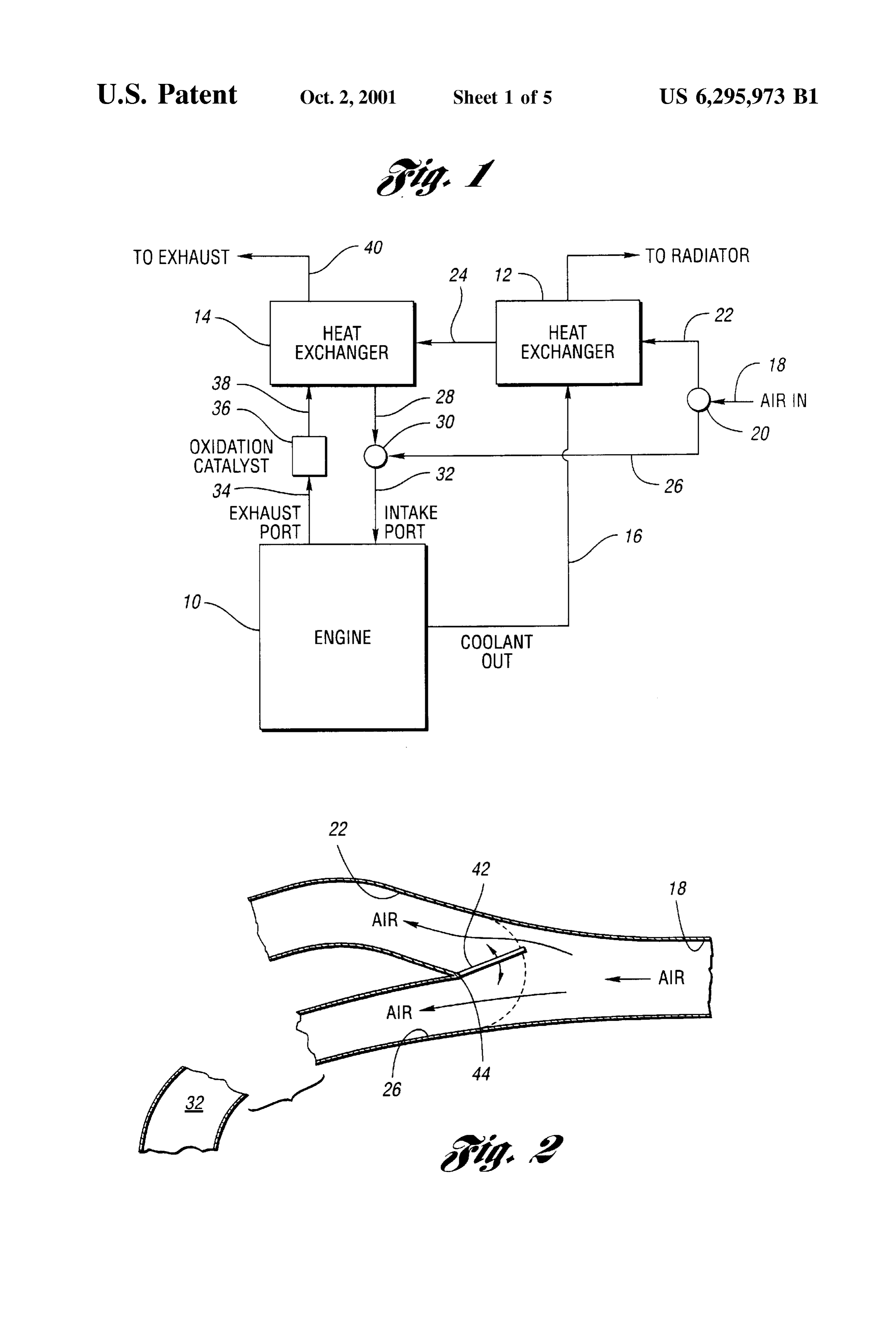
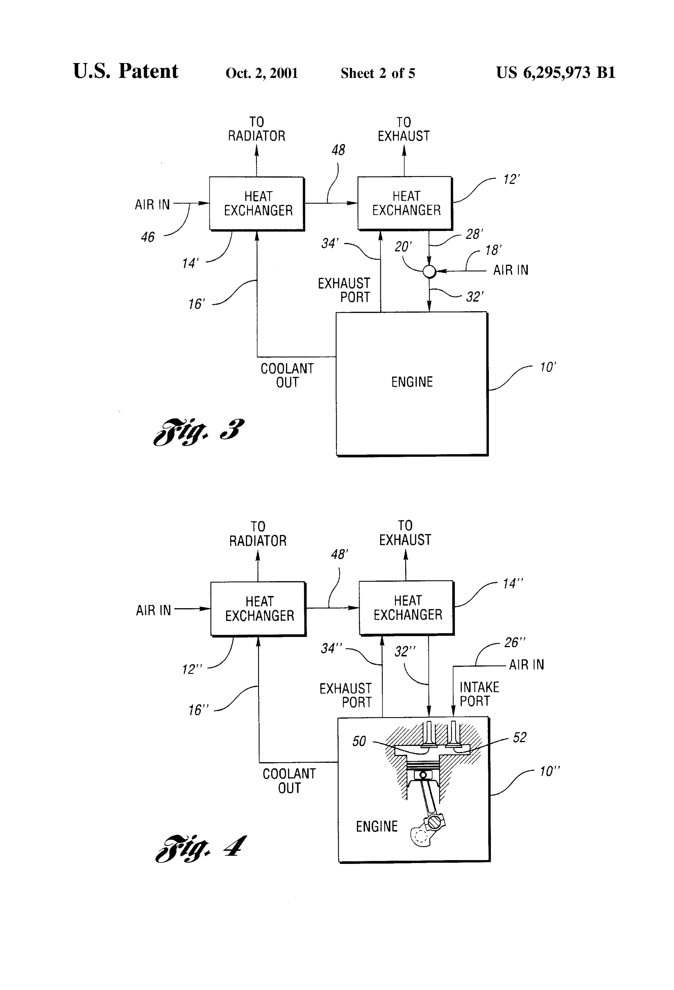
the invention; FIG. 2 shows a control valve at mixing point 20. The FIG. 4 is a second alternate embodiment of the HCCI 25 valve includes a movable damper plate valve 42, which is engine of the invention; pivoted at 44 on a Stationary portion of the intake manifold FIG. 5a is a plot showing the cylinder pressure and crank system. When it is in the position shown in FIG. 2, it angle relationship for a conventional Spark ignition engine; partially blocks the passage of air from passage 18 to FIG. 5b shows the relationship between crank angle and passage 22. It permits free flow of cool air from passage 18 combustion pressure for the HCCI engine of the invention; to passage 26.
When the valve 42 is moved in a clockwise direction
FIG. 6 is a plot of air-fuel ratio and the burn temperature for a Spark ignition engine of conventional design and for a about the pivot 44, a greater percentage of air will be HCCI engine; distributed through passage 22 compared to the air flow through passage 26.
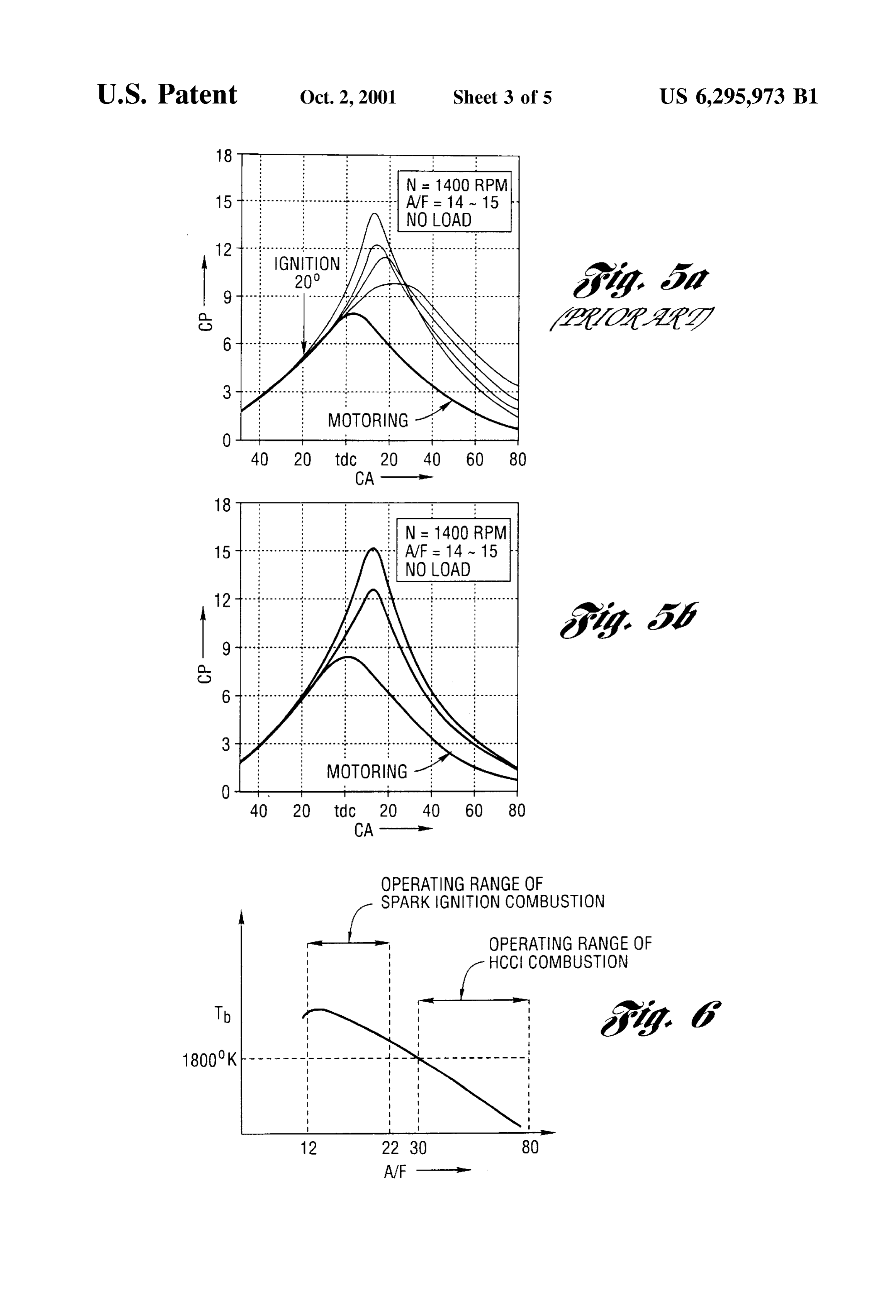
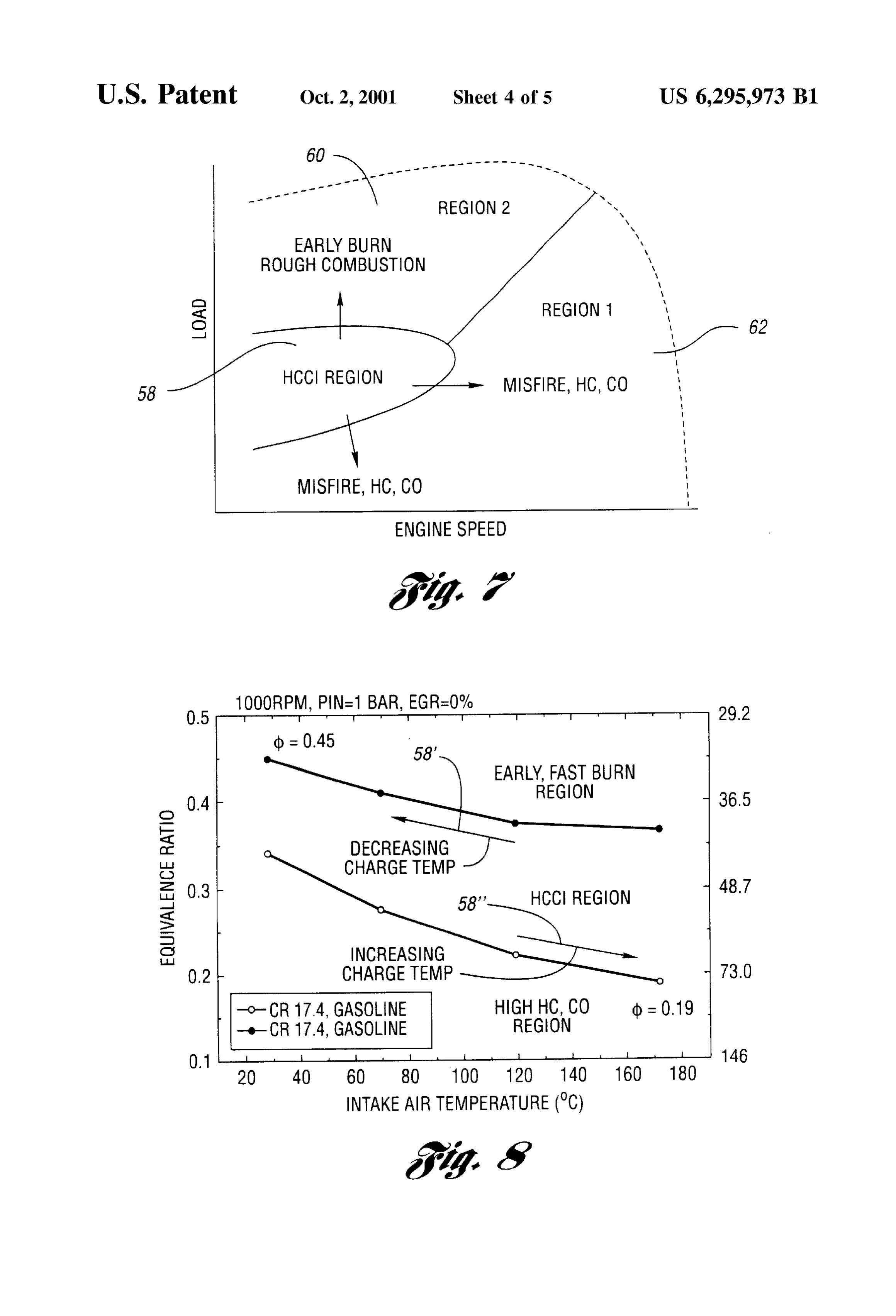
FIG. 7 is a plot of the load-speed characteristic for the 35
Air in passage 22 is heated by the heat eXchangers before
HCCI engine of the invention; it passes to mixing point 30 through passage 28 and to the FIG. 8 is a plot of equivalence ratio versus air intake passage 32. The temperature of the gases at the intake port temperature for the HCCI engine of the invention as the thus can be controlled by appropriately adjusting Valve 42. charge temperature is either decreased or increased; Adjustment of Valve 42 will result in a near instantaneous FIG. 9a is a schematic representation of another embodi 40 intake air temperature response.
ment of the invention wherein thermal energy is transferred In an alternative design, the valve 42 may be located at from the exhaust port to the intake manifold through a mixing point 30 rather than at mixing point 20. variable conductance heat pipe; The temperature of the mixed intake air at passage 32 FIG.9b is a schematic representation of the embodiment 45 depends upon the mass flow rates of the air in the two of the invention shown in FIG. 9a, but it illustrates a passages 22 and 26. The air in passage 22 is heated, and the multiple cylinder engine rather than the Single engine of air in passage 26 is cool. Variation of the air flow distribution FIG. 9a, and in these two passages will vary the effective air intake FIG. 10 is a Schematic, croSS-Sectional diagram of a heat temperature when operating conditions vary. pipe with variable conductance, which may be used in the 50 If the engine load increases to a high value, the engine embodiments shown in FIGS. 9a and 9b. combustion efficiency will become unacceptable because BEST MODE FOR PRACTICING THE the combustion rate would be too high due to the less diluted INVENTION mixture. The engine, when operating at Such high loads, then must be operated with a Spark ignition combustion mode.
FIG. 1 shows in schematic block diagram form a 55 Undesirable detonation or knocking, however, always is an homogeneous-charge, compression-ignition engine System issue when the engine is operating in the Spark ignition with one or more cylinders. It includes an internal combus combustion mode. To avoid detonation, the intake air tem tion engine 10. Engine coolant circulates through the engine perature should be as low as possible so that the effective block of the engine 10 in the usual fashion. The coolant compression ratio and the thermal efficiency can be as high flows through outlet coolant flow passage 16 at a tempera 60 as possible. To reduce the intake air temperature, the heated ture that typically would be about 90° C. It is received by air passage 22 is fully closed by the valve 42. Passage 26, heat eXchanger 12, which is a liquid-to-air heat eXchanger which is the cool air passage, at that time is fully opened. On that forms a part of the engine radiator. the other hand, when the engine load decreases, the engine An air intake flow passage 18 deliverS air to mixing point can be Switched from the Spark ignition combustion mode to 20. A portion of the intake air flow is distributed through 65 the homogeneous-charge, compression-ignition operating flow passage 22 to the heat eXchanger 12. The outlet Side of mode. The intake air temperature at that time must be the heat eXchanger 12 distributes heated air, typically at a boosted in order to achieve auto-ignition. To increase the air
Page 9
S 6 temperature, the heated air passage opens, and the unheated admitted to the combustion chamber can be controlled, air passage closes. thereby controlling the auto-ignition point. Because there is little or no thermal inertia involved in FIG. 5a is a representation of the relationship between Switching from one combustion mode to the other, the combustion pressure and crank angle for a Spark ignition temperature change response can be fast enough to allow a engine. FIG. 5a shows a family of curves for various rapid change in engine load. combustion cycles for a Spark ignition engine. There are FIG. 3 shows a variation of the homogeneous-charge, 5. wide cycle-to-cycle variations in the plots indicated in FIG. compression-ignition engine of the invention. AS in the case FIG. 5b is a plot corresponding to the plot of FIG. 5a, but of the system of FIG. 1, the system of FIG. 3 includes an 1O it indicates the relationship between combustion preSSure internal combustion engine 10', a first heat eXchanger 12", a and crank angle for the homogeneous-charge, compression Second heat eXchanger 14, and a Single mixing point 20'. ignition engine of the invention when the engine is operating There is no counterpart in the embodiment of FIG.3 for the in its optimum operating region. FIG. 5b indicates that there mixing point 30 seen in FIG. 1. are very Small cycle-to-cycle variations in the pressure Air is distributed to the mixing point 20' through intake air 15 Versus crank angle characteristic. flow passage 18". It is distributed to the intake port of the The plot of FIG. 6 represents the temperature of the burn engine through flow passage 32". Versus air-fuel ratio for a Spark ignition engine and for the The exhaust port of the engine distributes heated exhaust HCCI engine of the invention. Typically, the air-fuel mixture gases through passage 34 to the heat eXchanger 12'. This burns in a Spark ignition engine, following ignition, with a raises the temperature of the gases passing from the heat flame front that proceeds from the point of ignition through eXchanger 12' through passage 28". A Second inlet air out the combustion chamber region. AS the flame progresses passage, shown at 46, distributes air through heat eXchanger acroSS the combustion chamber, the temperature of the burn 14'. Engine coolant is distributed to the coolant outlet flow changes. If the air-fuel ratio is high, there is minimal passage 16' to the heat eXchanger 14'. nitrogen oxide (NO) in the exhaust gases. When the air-fuel The engine coolant heats the air introduced to the heat operating 25 ratio is low, the NO level is high. Typically, the air-fuel ratio exchanger 14' at 46. The outlet side of the heat exchanger 14 range for an internal combustion engine would be distributes heated air through passage 48 to the heat between 12 and 22.
eXchanger 12'. Thus, the thermal energy of exhaust gases, as In contrast to the narrow operating range for a Spark well as the thermal energy of the coolant, is distributed ignition engine shown in FIG. 6, the homogeneous-charge, compression-ignition engine of the invention can operate through the heat eXchangers to the mixing point 20' So that air introduced at 18' will be heated before it is transferred to with a very lean mixture (e.g., with an air-fuel ratio as high the intake port flow passage 32' together with the heated air as 80. The lean operation capability results in low burned gas in flow passage 28' that is introduced at intake air passage temperature (e.g., below 1800 K), and extremely low NO. 46. emissions. It also results in higher thermal efficiency due to A baffle-type control valve corresponding to the control heat 35 the reduced engine pumping loSS and higher gas specific ratioS.
valve shown in FIG. 2 is located at mixing point 20'. By It has been shown experimentally that the region of adjusting the angle of the baffle valve 42. The relative rates of flow through the cool air passage and through the heated optimum performance for the homogeneous-charge, combustion-ignition engine is limited without using the air passage can be adjusted, thereby controlling the auto ignition point in the engine combustion chamber. 40 teachings of the invention. This is demonstrated in the plot of FIG. 7 where the region for optimum performance is
In FIG. 3, prime notations are used with the reference shown at 58. FIG. 7 is a plot of the engine load versus engine numerals to indicate structures in the embodiment of FIG. 3
Speed. If the load on the engine should increase beyond the that have corresponding numerals in the embodiment of region 58, the burn of the combustible mixture is started by
45 auto-ignition too early to achieve efficient combustion. This
FIG. 4 shows an embodiment of the invention wherein operating region is identified by reference numeral 60 in two intake valves are used, one of which receives cool air FIG. 7. On the other hand, if the load on the engine should through cool air passage 26", which corresponds to the cool be decreased and the engine Speed load characteristic is air passage 26 in FIG. 1. The heated air passage 32", which shifted to region 62 in FIG. 7, the engine is susceptible to corresponds to heated air passage 32 in the embodiment of 50 misfire, which increases hydrocarbon emissions and carbon FIG. 1, communicates with a separate air intake valve. Air monoxide emissions.
in passage 32" is heated by heat eXchanger 14", which When the engine performance moves to either region 60 corresponds to the heat eXchanger 14 of the embodiment of or to region 62, the controller for the engine will automati FIG. 1. cally enter the Spark ignition operating mode, and the air Heat exchanger 12" in FIG. 4, which corresponds to the 55 valve 42, as seen in FIG.2, will be moved to the position that heat exchanger 12 in the embodiment of FIG. 1, receives hot will admit more cool air to the intake port. engine coolant through passage 16". Heat is transferred to The operating characteristics for region 60 can be the intake air by the heat exchanger 12" and is distributed to improved while the engine continues to operate in the the Second heat eXchanger 14 through passage 48". The homogeneous-charge, combustion-ignition mode by exhaust port for the engine 10" communicates with exhaust 60 decreasing the charge temperature. This is done by using the passage 34". air valve 42, by reducing internal exhaust gas recirculation, The intake valves for the engine 10" are identified by by controlling the coolant temperature, by controlling cool reference numerals 50 and 52. These, respectively, commu ant temperature, by retarding intake Valve closing time to nicate with the flow passages 32" and 26". The rates of flow reduce effective compression ratio, by using cooled external through the passages 26" and 32" can be controlled by 65 exhaust gas recirculation, or by Supercharging with inter controlling the valve timing and the valve opening for the cool. Any one or all Seven of these controls can be imple valves 50 and 52. In this way, the temperature of the charge mented.
Page 10
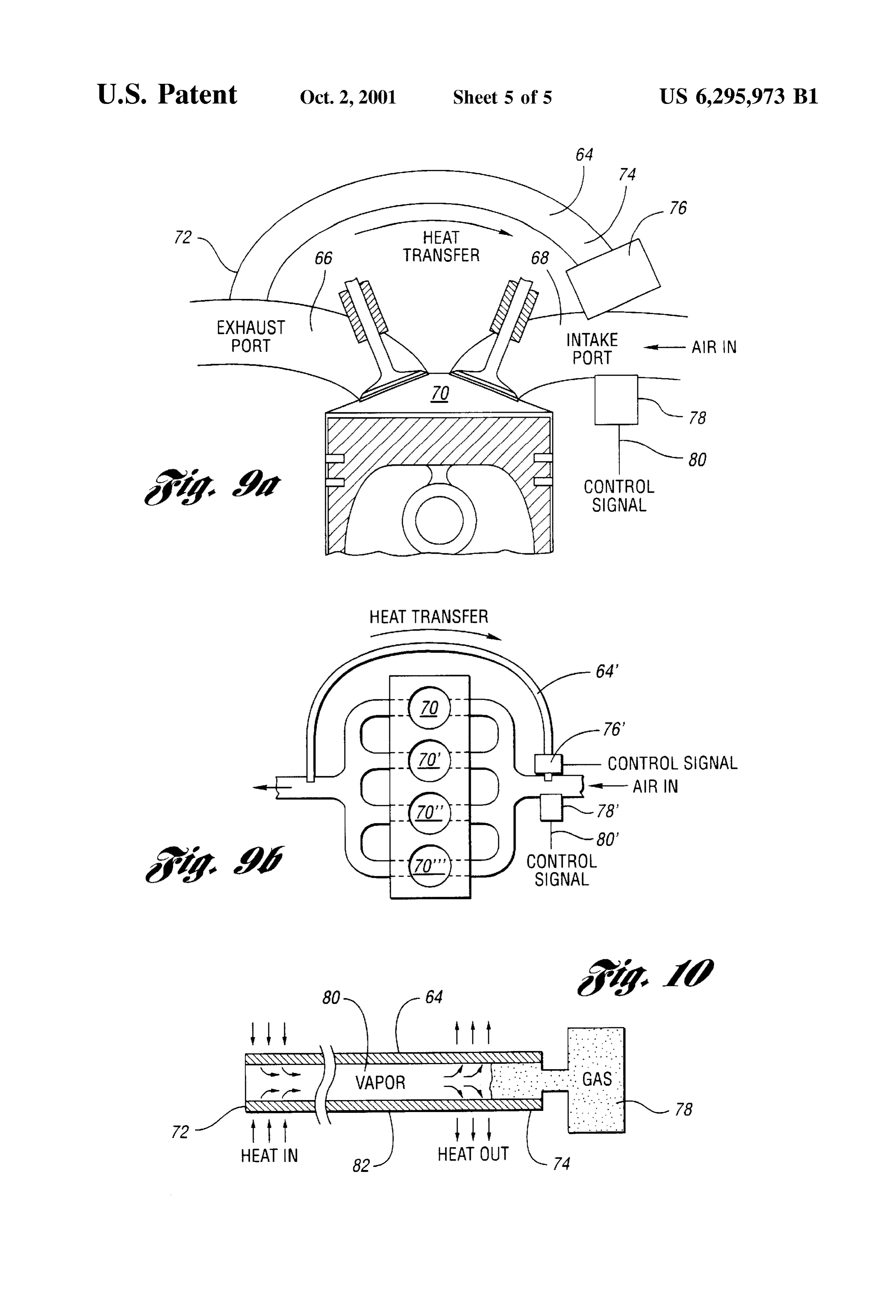
FIG. 8 shows the effect of decreasing or increasing the Heat pipes of this kind are commercially available from charge temperature in this fashion. The homogeneous Noren Products Incorporated, of Menlo Park, Calif. charge, compression-ignition operating region can be The embodiment of FIG.9b shows a single heat pipe for enlarged, as Seen in the plot of FIG. 8, by gradually controlling the inlet air for each of four cylinders rather than decreasing the air intake temperature to achieve a higher a single cylinder as illustrated in FIG. 9a. The cylinders are equivalence ratio. This relationship between equivalence identified in FIG.9b by reference numerals 70, 70, 70" and ratio and air intake temperature is shown by the upwardly 70". As in the case of the embodiment of FIG. 9a, the extending reference arrow 58' in FIG. 8a. For purposes of embodiment of FIG. 9b includes a conductance control this description, the equivalence ratio is defined as the ratio device 76', which may be a valve for controlling the rate of of the actual fuel-air ratio to the Stoichiometric ratio. transfer of liquid from one end of the heat pipe to the other. The performance of the engine in operating region 62 can To reduce the response time of the intake air heating, an be improved by increasing the charge temperature by heat electrical heater can be installed at the intake port, as Seen at 78 in FIG. 9a and at 78' in FIG.9b. This heater will work ing the intake air or using more exhaust gas recirculation, or only when the engine load decreaseS rapidly. AS the port by using engine coolant control. AS the intake air tempera temperature increases to a predetermined temperature for ture increases, the equivalence ratio will decrease as indi 15 any given load, the electrical heater is turned off, and the cated by the downwardly directed arrow 58" in FIG. 8b. heat pipe then functions in its normal fashion to heat the An alternate way to control ignition timing for a intake air.
homogenous-combustion, compression-ignition engine may The control devices 78 and 78 respond to a control signal include a heat pipe, as indicated in FIGS. 9a and 9b. The distributed to the heater through signal control lines 80 and engine system of FIGS. 9a and 9b includes a variable 80', seen respectively in FIGS. 9a and 9b. The control signal conductance heat pipe 64 that extends from exhaust port 66 is present for the electrical heaters when the engine proces to intake port 68. The intake port distributes air from the Sor identifies a Sudden increase in engine load. intake manifold to the combustion chamber 70. Exhaust Although the preferred embodiments of the invention gases from the chamber 70 pass through exhaust port 66, 25 have been disclosed, it will be apparent to perSons skilled in thereby raising the temperature of the heat input end 72 of the art that modifications may be made to the invention the heat pipe 64. The heat output end of the heat pipe 64 is without departing from the Scope of the invention. All Such seen at 74. modifications and equivalents thereof are covered by the The interior of the heat pipe contains a vapor. A vapor following claims.
flow control valve or heat conductance valve 76 may be used What is claimed is:
to control the flow of the vapor in the heat pipe. In this way, 1. A homogeneous-charge, compression-ignition engine the amount of heat transferred from the exhaust port 66 to System having a gas charge intake manifold and an exhaust the intake port 68 can be controlled. gas manifold, an engine having a gas charge combustion This variable conductance heat pipe concept can be chamber, a gas charge intake in the combustion chamber understood by referring to FIG. 10. As seen in FIG. 10, the 35 communicating with the intake manifold, and an exhaust heat pipe 64 is connected to a reservoir 78 of relatively large port in the combustion chamber communicating with the Volume, which is filled with a non-condensing gas. The exhaust manifold;
thermal conductance of the heat pipe is automatically varied means for recovering thermal energy of exhaust gas and by blocking the action of the non-condensing gas in the for transferring it to the gas charge in the intake reservoir. During normal operation, the interior of the heat 40 manifold; and pipe, which contains a working fluid vapor 80, tends to means for adjusting the rate of heat transfer from the pump the non-condensing gas back into the reservoir. The exhaust manifold to the combustion chamber whereby Vapor-gas interface is located at variable positions along the timing of auto-ignition of the air-fuel mixture in the condenser 82. The presence of a non-condensable gas in a combustion chamber is controlled during a combustion portion of the condenser prevents the vapor from condensing 45 cycle.
in that area. 2. A homogeneous-charge, compression-ignition engine When the heat load at the source 72 increases, the vapor System having a gas charge intake manifold and an exhaust preSSure in the active portion of the heat pipe rises, com gas manifold, an engine having a gas charge combustion presses the gas and increases the active region of the chamber, a gas charge intake in the combustion chamber condenser. This has the effect of reducing the interface 50 communicating with the intake manifold, and an exhaust thermal resistance. The effect of the increased heat load is to port in the combustion chamber communicating with the reduce the internal thermal resistance of the condenser, exhaust manifold;
which in turn counterbalances the increase in vapor pressure means for recovering thermal energy of exhaust gas and and the heat transfer rate. The heat pipe temperature then can for transferring it to the gas charge in the intake be maintained in a desired range. 55 manifold; and
The heat pipe consists of a Sealed aluminum or copper means for adjusting the rate of heat transfer from the container with inner Surfaces that have a capillary wicking exhaust manifold to the combustion chamber whereby material. The interior of the container is a liquid under its timing of auto ignition of the air/fuel mixture in the own pressure. The liquid enters the pores of the capillary combustion chamber is controlled during a combustion material, thereby wetting all internal Surfaces. When heat is 60 cycle;
applied at 72 along the Surface of the heat pipe, the liquid at the means for recovering and transferring thermal energy that point tends to boil and enter a vapor state. When that comprising a heat tube with a heat input Zone in thermal happens, the liquid picks up the latent heat of vaporization. communication with the exhaust manifold and a heat The gas, which then has a higher pressure, moves inside the outlet Zone in thermal communication with the intake Sealed container to a cooler location where it condenses. The 65 manifold.
gas thus gives off its latent heat of vaporization and moves 3. The system set forth in claim 1 wherein the engine heat from the input end to the output end of the heat pipe. includes Spark ignition means in the combustion chamber
Page 11
for igniting the gas charge delivered to the combustion opposite direction whereby the effective temperature of chamber when the engine load increases for a given engine air-fuel mixture in the intake manifold is controlled thus Speed to an operating region in which homogeneous-charge controlling the point of auto-ignition of the air-fuel mixture burning in the combustion chamber is not stable and when in the combustion chamber.
the engine Speed increases for a given engine load to an 5 8. The system set forth in claim 7 wherein the heat operating region in which homogeneous-charge burning in eXchanger communicates with the exhaust manifold the combustion chamber is not stable. whereby heat of the exhaust gas in the exhaust manifold is 4. The system set forth in claim 1 wherein the engine has transmitted to inlet air-fuel mixtures in the intake manifold. multiple combustion chambers, each combustion chamber 9. The system set forth in claim 8 wherein the engine having an intake valve and an exhaust valve, an intake includes engine coolant that is heated by combustion occur manifold communicating with each intake valve and an ring in the combustion chamber, the System including fur exhaust manifold communicating with each exhaust valve; ther a Second heat eXchanger in the Second flow passage in the means for recovering thermal energy and for trans Series relationship with respect to the heat eXchanger com ferring it to the gas charge in the intake manifold being municating with the exhaust manifold, and a coolant flow common to each of the multiple combustion chambers. 15 passage extending from the engine to the Second heat 5. A homogeneous-charge, compression-ignition engine eXchanger whereby thermal energy in the coolant is trans having an engine coolant passage, a gas charge intake ferred to the air in the Second flow passage. manifold and an exhaust gas manifold, an engine having a 10. The engine system set forth in claim 6 wherein the gas charge combustion chamber, a gas charge intake in the means for controlling the maSS air ratio of heated air and combustion chamber communicating with the intake unheated air comprises two intake valves in the combustion manifold, an exhaust port in the combustion chamber com one of theeach chamber, intake valve communicating with a separate flow passages, each intake valve being control municating with the exhaust manifold; lable to effect variable mass air ratio of heated air and means for recovering thermal energy of exhaust gas and unheated air.
engine coolant and for transferring it to gas charge in 25 11. The system set forth in claim 6 wherein the engine the intake manifold; and includes Spark ignition means in the combustion chamber means for adjusting the rate of heat transfer from the for igniting the gas charge delivered to the combustion exhaust gas manifold and engine coolant to the intake chamber when the engine load increases for a given engine manifold whereby timing of auto-ignition of the air Speed to an operating region in which homogeneous-charge fuel mixture in the combustion chamber is controlled burning in the combustion chamber is not stable and when during a combustion cycle. the engine Speed increases for a given engine load to an 6. A homogeneous-charge, compression-ignition engine operating region in which homogeneous-charge burning in System having a gas charge intake manifold and an exhaust the combustion chamber is not stable.
gas manifold, an engine having an air-fuel combustion 12. A homogeneous-charge, compression-ignition engine chamber, a gas charge intake manifold, a combustion cham 35 System having a charge intake manifold and an exhaust gas ber communicating with the intake manifold and an exhaust manifold, an engine having a cylinder housing with engine port in the combustion chamber communicating with the coolant, an air-fuel combustion chamber, a charge intake exhaust manifold; port, a combustion chamber communicating with the intake a split inlet port communicating with the intake manifold, manifold and an exhaust port in the combustion chamber the intake port having first and Second flow passages, 40 communicating with the exhaust manifold; the first flow passage communicating directly with the a split inlet port communicating with the intake manifold, intake manifold whereby unheated ambient air is dis the intake port having first and Second flow passages, tributed to the intake manifold; the first flow passage communicating directly with the a heat eXchanger communicating with the Second flow intake manifold whereby unheated ambient air is dis passage and with the exhaust manifold, the Second flow 45 tributed to the intake manifold; passage communicating with the intake manifold a first heat eXchanger communicating with the Second through the heat eXchanger whereby air heated by flow passage and with the exhaust manifold, the Second exhaust gas is distributed to the intake manifold; and flow passage communicating with the intake manifold Valve means for controlling the mass air ratio of heated air through the first heat eXchanger whereby air heated by and unheated air delivered to the combustion chamber 50 exhaust gas is distributed to the intake manifold; whereby the mass air ratio is adjusted to control the a Second heat eXchanger communicating with the engine auto-ignition point in the combustion cycle and thereby coolant and with the Second flow passage through the establish optimum combustion efficiency. first heat eXchanger whereby thermal energy is trans 7. The homogeneous-charge, compression-ignition ferred from the engine coolant to the intake manifold; engine System Set forth in claim 6 wherein the valve means 55 and comprises an adjustable valve plate at flow entrance loca Valve means for controlling the mass air ratio of heated air tions of the first and Second flow passages, the valve plate and unheated air delivered to the intake manifold reducing air flow through the first flow passage and increas whereby the mass air ratio is adjusted to establish the ing air flow through the Second flow passage when it is auto-ignition point in the combustion cycle and thereby adjusted in one direction, the valve plate increasing air flow 60 establish optimum combustion efficiency. through the first flow passage and decreasing air flow through the Second flow passage when it is adjusted in the k k k k k
Provenance
- Collection
- Cited prior art
- Original PDF
- patentimages.storage.googleapis.com →
- Filed
- 1999-12-22
- Pages
- 11
- Method
- pdftotext (the PDF's own text layer) + pdftoppm 300dpi page scans
- Source
- Google Patents bibliographic record
- Granted
- 2001-10-02
- Inventors
- Jialin Yang; Ford Global Technologies LLC
- Transcribed from
- patentimages.storage.googleapis.com →