patent · US2869514
Air cylinder
20 January 1959
Page 1
Jan. 20, 1959 N. GLUSS 2,869,514
AIR CYLINDER
Filed July 26, l956
29, AR
PRESSURE
N ill-Eate EZElYas
NetNels s3N
Ol. PRESSURE
Esta
iii.22 flize
NVENTOR
35-5 49 NORMAN GLUSS
Page 2
United States Patent Office 2,869,514 Patented Jan. 20, 1959
brakes and engines; and that the apparatus of the in vention may utilize other streams of fluid, either gas or liquid, as the motivating medium.
2,869,514 According to the present invention, improved lubri
AR CYLNDER
cation of inaccessible cylinder parts, particularly mini ature cylinder parts, may be effected through the use of
Norman Gluss, Stamford, Conn. a lubricant reservoir which encompasses the cylinder wall, and the provision of a lubricant-permeable cylinder wall
Application July 26, 1956, Serial No. 600,276 which affords means for the transmission of lubricant 2 Claims. (Cl. 121-1) from the reservoir to the inside wall of the cylinder. A pressure take-off line in the lubricant reservoir operates in accordance with the pressure inside the cylinder to ad justably regulate the flow of lubricant, so that lubricant is neither flooded into the cylinder, nor blown back
This invention relates to the lubrication of cylinder 5 through the pores of the cylinder parts. An obvious parts, and more particularly concerns a self-lubricating advantage of such an arrangement is that the frequent air cylinder for use in engines such as model railroad oiling of cylinder parts may be avoided. In addition, a engines. uniform Supply of lubricant is assured over extended peri In spite of the large amount of development work which 20 ods of time, thus obviating the need for frequent inspec has been expended upon lubrication, the problem of lubri tions, and contributing to the simplification and ease of cating inaccessible engine parts is still a continuing one. operating procedure. When constructed as described be Without good lubrication the engine parts wear against low, the cylinder parts are extremely rugged, and have each other, and eventually impair the usefulness of the longer wear resistance.
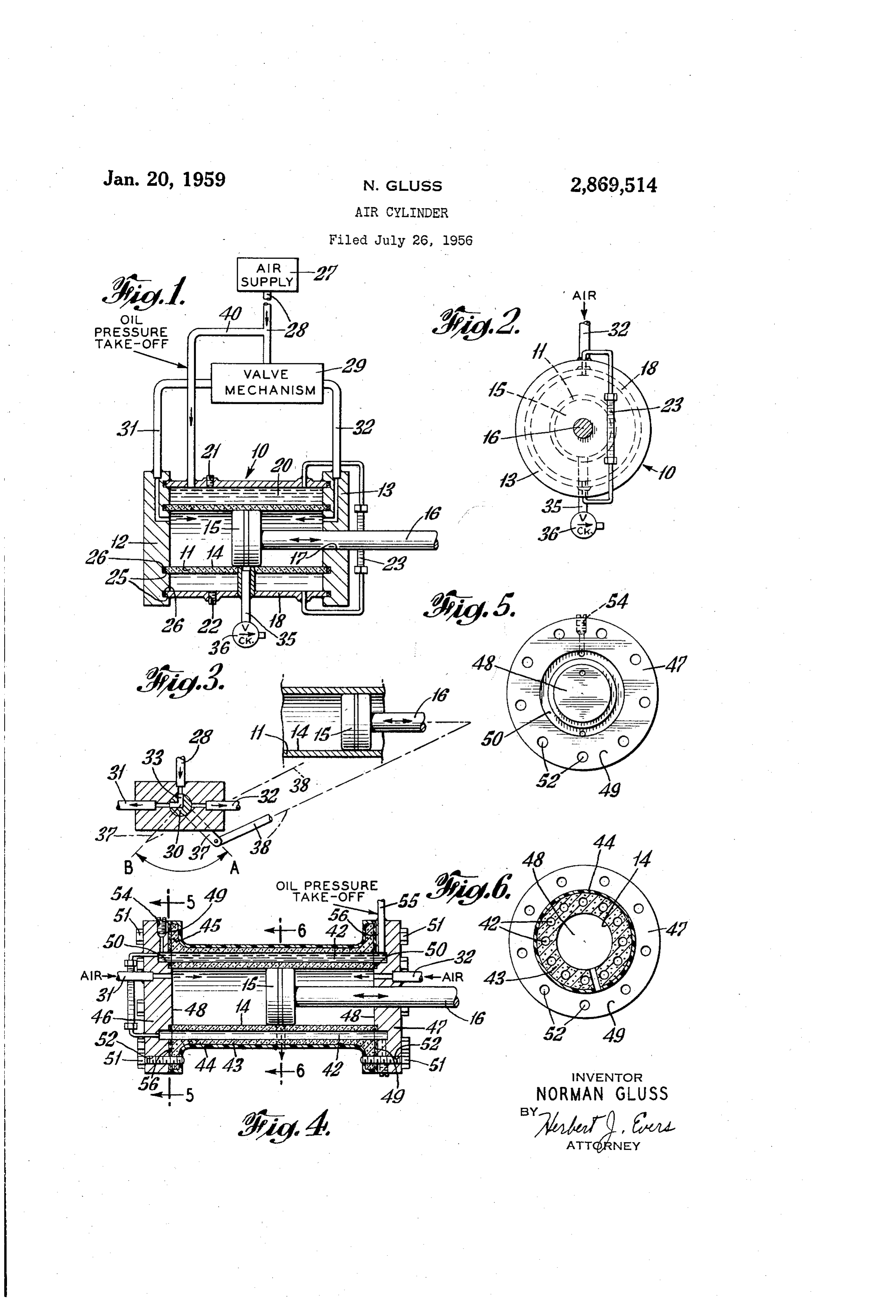
engine. Referring now to Figs. 1 to 4, it will be seen that a For example, in a miniature engine employing a pre 25. motor or air cylinder assembly 10 embodying the prin cision made air cylinder having a closely fitting piston ciples of the present invention may include a hollow reciprocating therein, the reduced sizes and inaccessibility cylinder block or cylinder head 11 normally composed of the parts are some of the elements which limit the of porous metal, through which a light oil may readily practicability of the normal methods of lubrication. The 30 diffuse, and a pair of end flanges or closure plates 12, fact that the air cylinder may occupy a space less than 13 enclosing the bore 14 of the cylinder head 11 at the one cubic inch means that the normal size lubricating ends thereof. Tightly fitting into the bore 14 is a cylin groove or opening would provide an excessive amount of drical piston 15 of substantially conventional construction lubricant. Restricting the size of the lubrication inlet including piston rings, said piston having secured thereto would require greatly increased pressures for the supply 35 an elongated piston rod 16 extending through an air-tight of proper lubrication. Both of these effects necessitate opening 7 in the end plate 3.
the use of auxiliary equipment, the conventional lubri A non-porous shell 18 concentrically disposed about the cant opening requiring a larger oil storage capacity, and cylinder block 11 forms the outer wall of the air cylin the restricted size lubricant opening requiring pressure der 10, and defines an annular oil chamber or reservoir building apparatus, which of course adds to the overal 40 26 between the shell and the cylinder block. Lubricating size of the unit. In order that precision made machines oil may be supplied to the reservoir and replenished of the above type operate with maximum efficiency, it is through a supply opening 2A in the shell 18, and may be necessary that the detrimental rubbing action in inac removed through a drain hole 22 in the bottom surface cessible parts be substantially reduced or eliminated. of the shell. The reservoir 20 may be of any desired It is, therefore, an important object of the present. size, depending upon space requirements, since the reser invention to provide improved lubricating means in a 45 voir may be in communication with a remote oil supply cylinder and piston construction, which is adapted for tank. For example, in miniature engines where space is embodiment in precision made units such as miniature at a premium, it is desirable that the reservoir space be power plants. held to a minimum. A sight gage 23 constitutes means Other objects, features and advantages of the present whereby the oil level in the reservoir may be determined. invention will be apparent from the following detailed 50 To maintain the cleanliness of the lubricant contained description of certain preferred embodiments thereof within the reservoir, and to guard against foreign matter taken in conjunction with the accompanying drawings, and moisture entering the reservoir, the inner faces of in which: - the end plates 2 and 13 are provided with a pair of Fig. 1 is a flow diagram of the air cylinder apparatus concentric annular recesses 25 having interfitting there illustrating the principles of the present invention; 55 in sealing gaskets 26 in registry respectively with the Fig. 2 is an end view of the air cylinder shown in ends of the cylinder block 11 and shell 18. Fig. 1; The motor i0 of the invention may be either single Fig. 3 is an illustrative valve linkage diagram em acting or double acting, the latter being illustrated and ployed in conjunction with the air cylinder apparatus of described herein. Compressed air from an air supply the invention; 60 source 27, which may be remotely positioned with respect. Fig. 4 is a sectional elevational view of a modifica to the air cylinder 10, flows through an air line 28 into tion of the air cylinder shown in Fig. 1; a valve mechanism 29, for example, a two-way cock valve Fig. 5 is an end view taken along line 5-5 in Fig. 4; 30, see Fig. 3, where it is directed into either of cylinder and inlet lines 31 or 32. With the valve in the position “A” Fig. 6 is a sectional view taken along lines 6-6 in 65 shown in Fig. 3, the valve passageway 33 connects the Fig. 4. air supply line 28 with the cylinder inlet 31, and allows The invention will be described in connection with an the air to push against the piston face and propel the air cylinder, i. e., using compressed air as the means of piston 15 from left to right. As the piston 15 moves past propulsion. However, it is to be understood that the the center of the cylinder 11, it uncovers a suitable uni principles of the invention are susceptible of application flow exhaust conduit 35, which discharges the air past a in other devices, such as turbines, reciprocating engines 70 check valve 36 into the atmosphere. both single acting and double acting, compressors, motors, Clock-wise rotation of the valve 30 about its center
Page 3
through approximately a 90° arc to a position “B” joins having an outer oil-impermeable covering or seal 44, the air supply line 28 with the cylinder inlet line 32, and such as heavy gage polyethylene, for retaining the oil allows the air to act on the opposing face of the piston 15 within the confines of the cylinder. The cylinder wall to drive it in the opposite direction. 43 may be provided at each end with an end flange 45, A feature of the invention lies in the fact that the 5 and the cylinder bore 14 enclosed by a pair of end plates system is capable of satisfactory operation with a two 46 and 47, each having a central face 48 and a coplanar position cock valve. Positioning of the cock valve 30 annular margin face 49, and defining an annular recess imay be varied by a valve crank arm 37 and a valve or groove 50, see Figs. 4 and 5. In assembly the faces rod arm 38, the crank arm 37 having one end perpendic of the end plates 46, 47 are retained in abutment with ularly attached to the axis of the cock valve for rotary the cylinder ends by spaced bolts 51 passing through movement thereabout, and the crank rod 3S having the registering bct holes 52 in the end plates and cylinder ends pivotally attached respectively to the ends of the flanges, so that the recess 50 registers with the cylinder crank arm 37 and piston rod 16. lubricant passages 42.
Since the moving elements of the air cylinder are In order that the lubricant may be supplied to each 'usually very small and have very little clearance, it is of the lubricant holes 42 in the cylinder, there is provided important that they be protected against detrimental an oil inlet 54 in the end plate 46, in communication metal to metal contact without proper lubrication. Ac with the recess 50. In this fashion all the cylinder holes cording to the invention, self-lubrication of the moving 42 may be lubricated from single inlet 54. An opening parts of the air cylinder is accomplished through the 55 in the end plate 47 provides the necessary lubricant walls of the cylinder block 1. Communication is es 20 pressure, and may be joined to the air supply line 28 in tablished between the lubricant reservoir 20 and the in the same manner shown in Fig. 1. Suitable gaskets, side wall of the cylinder a through suitable apertures in such as felted sealing gaskets 56, may be provided in the the cylinder wall, or preferably through the pores of recesses 50 to prevent leakage of oil. the cylinder wall. From the above it will be seen that the present inven A pressure take-off line is provided by a branch con tion provides a self-lubricating cylinder for an air pump, duit 40, which joins the air supply line 28 at one end, wherein the cylinder is provided with a porous cylinder and is connected at the other end through an opening in wall, the cylinder wall being surrounded by an oil cham the shell 8 to the reservoir 20. Lubricant under pres ber having the same chamber pressure as the high pres sure is thereby permitted to flow through the pores of 30 Sure sidic of the cylinder piston, the cylinder block into the low pressure side of the It will be understood that variations and modifications cylinder. Air on the other hand is prevented from flow may be effected without departing from the spirit and ing into the lubricant reservoir 20 on the high pressure Scope of the novel concepts of the present invention. side of the cylinder piston through the pressure equal What is claimed is:
izing action between said high pressure side and the reser 1. A reciprocating air engine comprising a cylinder voir brought about by the pressure take-off line 40. of porous material, a piston reciprocably movable there in metals, porosity has made it possible to produce in, an outer shell Surrounding the cylinder, a pair of end oil impregnated, self-lubricating metals for bearings. I plates disposed respectively at opposite ends of said cylin have found that lubrication can be uniformly supplied der in abutting and sealing relation with the ends of said through the pores of the cylinder wall and other de cylinder and said shell, thereby defining an enclosed 'sirable properties of the cylinder enhanced by employing 40 annular lubricant reservoir space between said shell and a suitably porous material such as a cylinder wall having said cylinder wall, an air supply line gas-tightly connected an anti-friction facing consisting of porous ferrous mate to said end plates for supplying compressed air to said rial including not more than 1.25% phosphorous and be cylinder, valve means for directing said air supply al tween 0.5% and 1.0% of combined carbon. ternatingly on each side of the piston, and a pressure A very significant advantage of the invention arises 45 take-off line in communication with said lubricant reser from the fluid seal achieved between the piston and the voir space and connected with said air supply line for cylinder wall, in that loss of compression along the sides equalizing pressure between a portion of said cylinder of the piston is prevented while the efficiency of the and said lubricating space.
engine is improved. 2. A reciprocating air engine comprising a cylinder In addition to the foregoing, cylinder parts made in 50 of porous material, a piston reciprocably movable there accordance with the present invention do not accumulate in, an outer shell surrounding the cylinder, a pair of end significant amounts of deposit on their faces, and evidence plates disposed respectively at opposite ends of said cylin no measurable loss in wear life after extended operation der in abutting and sealing relation with the ends of said of the engine. This is in marked contrast to several cylinder and said shell, thereby defining an enclosed commercial air cylinders which have had substantial af annular lubricant reservoir space between said shell and said cylinder wall, an air supply line gas-tightly connected finity for dirt and other deposits, and lost a substantial to said end plates for supplying compressed air to said amount of wear during normal operation of the engine. cylinder, valve means for directing said air supply al Various changes and modifications will suggest them ternatingly on each side of the piston, and a pressure selves to those skilled in the art. For example, the cock valve 30 and piston crank arm 37 can be arranged to be take-off line in communication with said lubricant reser completely enclosed in a bath of lubricant or immersed voir space and connected with said air supply line for equalizing pressure between said cylinder and said lub directly in the lubricant reservoir 20, so that the valve ricating space, said valve means being automatically parts are protected from dust, chips and moisture.
In the modification shown in Figs. 4, 5 and 6, the an controllied by the reciprocal movement of said piston. nular reservoir 20 may be replaced with a circular series of spaced, open ended, longitudinal lubricant passages References Cited in the file of this patent acting as reservoirs in the form of cylindrical holes or UNITED STATES PATENTS openings 42 in the cylinder wall coextensive with the 1,360,497 Cass ------------------ Nov. 30, 1920 length or stroke of the cylinder. The openings. 42 may 1,634,768 Bonner ---------------- July 5, 1927 be provided in a porous-bearing metal liner or insert 70 1,910,019 Kelly ------------------ May 23, 1933 press-fitted into an outer steel cylinder shell, or, as illus 2,610,096 Mallory ---------------. Sept. 9, 1952 itrated in Figs. 4 and 6, the longitudinal openings 42 may 2,696,410 Topanelian ------------- Dec. 7, 1954 be provided in a suitably thick porous cylinder wall 43
Provenance
- Collection
- Cited prior art
- Original PDF
- patentimages.storage.googleapis.com →
- Filed
- 1956-07-26
- Pages
- 3
- Method
- pdftotext (the PDF's own text layer) + pdftoppm 300dpi page scans
- Source
- Google Patents bibliographic record
- Granted
- 1959-01-20
- Inventors
- Gluss Norman
- Transcribed from
- patentimages.storage.googleapis.com →