patent · US5408973
Internal combustion engine fuel supply system and method
25 April 1995
Page 1 — bibliographic record
United States Patent (19) 11) Patent Number: 5,408,973 Spangjer (45) Date of Patent: Apr. 25, 1995 54 INTERNAL COMBUSTION ENGINE FUEL 4,590,912 5/1986 Atago .................................. 123/478 SUPPLY SYSTEMAND METHOD 4,611,567 9/1986 Covey ................................. 123/557 4,644,925 2/1987 Hoppie et al. ...................... 123/558 76 Inventor: Keith G. Spangjer, 8537 E. Orange 4,669,433 6/1987 Hoppie........... 123/538 Blossom, Scottsdale, Ariz. 852.50 4,784,092 11/1988 Pitti ................ 123/525 4,909,192 3/1990 Förster et al. . 123/557 (21) Appl. No.: 157,540 4,926,831 5/1990 Earl ..... 123/557 22 Filed: Nov. 26, 1993 5,035,227 7/1991 Hansen ... ... 123/557 5,092,303 3/1992 Brown ................................. 123/538 51) Int. Cl. ............................................. FO2M 31/00 Primary Examiner-Andrew M. Dolinar 52 U.S. C. .................................... 123/478; 123/557; Assistant Examiner-M. Macy 123/538; 123/556; 123/555 Attorney, Agent, or Firm-Cahill, Sutton & Thomas
123/545, 552, 536,537, 538, 472, 478; 65/110, 57 ABSTRACT
A fuel supply system and method incorporates a fuel 56) References Cited pump for pressurizing liquid fuel for use in an internal
fuel injector mounted on a vaporization chamber; actua 756,834 4/1904 Denison .............................. 123/557 tion signals applied to the fuel injector atomize a me 1,217,233 2/1917 Squire ................................. 123/555 tered quantity of liquid fuel into the chamber. The at 1,325,850 12/1919 Humphreys ......................... 123/557 omized fuel travels a tortuous pathin the chamber strik
3,496,919 2/1970 Gerrard ............................... 123/545 ing chamber walls heated by hot exhaust gas from the 3,762,378 10/1973 Bitonti................................. 123/557 internal combustion engine. Vaporized fuels delivered 3,765,382 10/1973 Vandenberg........................ 123/557 from the vaporization chamber to a mixing chamber to 4,106,453 8/1978 Burley ................................ 123/555 be mixed with air to form a combustible fuel/air mix 4,112,896 9/1978 Akado et al........................ 123/556 ture. Air supplied to the mixing chamber is heated by 4,126,110 11/1978 Simmons ............................. 123/556 exhaust heat prior to delivery to the mixing chamber. 4,161,930 7/1979 Bendig et al........................ 123/556 The combustible fuel/air mixture is then supplied to the
4,267,976 5/1981 Chatwin .............................. 123/538 intake manifold of the internal combustion engine. 4,372,278 2/1983 Smith .................................. 123/478 4,550,706 11/1985 Hoffman ............................. 123/557 16 Claims, 3 Drawing Sheets
Page 2
Drawing sheet — no readable text.
Page 3
Drawing sheet — no readable text.
Page 4
Drawing sheet — no readable text.
Page 5
INTERNAL COMBUSTON ENGINE FUEL
ized fuel to a mixing device such as a carburetor to
SUPPLY SYSTEMAND METHOD
provide an appropriate fuel/air mixture. Such prior art vapor carburetors have not been able to provide a
FIELD OF THE INVENTION
means for controlling the vaporization of the liquid fuel so as to insure complete vaporization while supplying
The present invention relates to an internal combus and controlling the quantity of vapor provided to the tion engine fuel system, and more particularly to sys fuel/air mixing device.
tems and methods for vaporizing liquid fuel for mixing OBJECTS OF THE INVENTION with air to be used as a combustible mixture in the en glne. 10
It is therefore an object of the present invention to
BACKGROUND OF THE INVENTION provide an improved fuel supply system and method for use in an internal combustion engine.
Present day internal combustion engines, such as the It is also an object of the present invention to provide typical automotive engine, require that a fuel/air mix 15 a fuel supply system and method incorporating a fuel ture be delivered to each of the combustion chambers to subsequently be ignited for the extraction of energy to a liquid fueltechnique vaporizing prior to to insure complete vaporization of mixing the fuel with air.
produce the work of the engine. Creating a fuel/air mixture having the proper proportions to provide clean vide an improved fuel supplypresent
It is another object of the invention to pro and efficient burning of the fuel has been the purpose of internal combustion engine wherein for system use with an a vaporization fuel delivery systems in the prior art. The conventional chamber is utilized to extract the heat of the engine carburetor attempts to provide the appropriate fuel/air exhaust mixture throughout a broad range of engine operation for the vaporization of a metered quantity of by metering liquid fuel into an air stream; elaborate liquid fuel to be mixed with air for use in the engine. techniques have been employed to achieve the correct It is still another object of the present invention to fuel/air mixture throughout a broad range of engine 25 provide an internal combustion engine fuel supply sys operation. However, the liquid fuel is seldom com tem having a vaporization chamber incorporating a pletely vaporized in the ideal proportions and the result tortuous path for guiding metered quantities of liquid ing fuel/air mixture is poorly controlled, poorly distrib fuel to be vaporized therein and wherein engine exhaust uted, and very inefficiently utilized. heat is utilized to supply the heat of vaporization. In an attempt to more accurately control the fuel/air 30 It is still another object of the present invention to mixture to meet the varying demands of the engine provide an improved fuel supply system and method for during operation, fuel injection systems have been em an internal combustion engine wherein engine operating ployed for directing a measured spray or atomized parameters as detected by conventional sensors are quantity of liquid fuel into an air stream to be mixed utilized to control a liquid fuel metering system for the with the air to provide a fuel/air mixture for combus 35 injection of the liquid fuel into a vaporization chamber. tion. Such atomizers or fuel injectors have been placed These and other objects of the present invention will in the same position as conventional carburetors (throt become apparent to those skilled in the art at the de tle body injection) or more efficiently have been distrib scription thereof proceeds.
uted along the intake manifold with an injector located at an appropriate position adjacent each inlet of the SUMMARY OF THE INVENTION respective cylinders. With the advent of more sophisti Briefly, in accordance with the embodiment chosen cated electronic controls, it has been possible to more for illustration, the present invention uses components accurately control the operation of these fuel injectors which are generally readily available for use with the for the measurement of the correct amount of liquid fuel to be injected into the air stream to provide a proper 45 internal combustion engines. Fuel, such as gasoline or a fuel/air mixture. Numerous engine operational parame stored inofa gasoline mixture with other fuels such as alcohol, is ters can be sensed and converted into appropriate elec ventional fuel pump toandsupply fuel tank is pressurized utilizing a con pressurized fuel to a fuel trical signals for application through a computerized system to electrically energize the respective fuel injec atomization device such as a fuel injector. The fuel tors at the appropriate time and duration. 50 injector may be of a type presently readily available and All of the above prior art systems depend upon the which is electrically actuated to provide a fine spray of introduction of liquid fuel into an air stream. The fuel liquid fuel into a vaporization chamber. The fuel injec /air mixture that is required for proper combustion is a tor may operate for periods, the frequency and duration mixture of air and fuel vapor; therefore, for ideal mix of which are determined in accordance with engine demands, to supply liquid fuel to the vaporization ing, fuel vapor, and not liquid fuel, should be the con 55 chamber.
stituent to be mixed with the air. Incomplete or uneven vaporization of fuel causing variations in the mixture The vaporization chamber is mounted within the ratio or imbalances in the mixture delivered to different engine exhaust gas stream and provides a tortuous path cylinders greatly reduces the efficiency of the overall for the liquid fuel/fuel vapor as the vapor travels the engine system. Further, improper fuel/air mixtures or length of the chamber. The vaporization chamber is improper control of the mixture and deviation of the constructed to insure the impact of liquid fuel droplets mixture from ideal is a major contributor to atmo with the walls of the chamber with the subsequent con spheric polluting combustion products. plete vaporization of the liquid fuel. The vaporization Prior art fuel supply systems also include techniques chamber is constructed so that the liquid droplets en for vaporizing the liquid fuel prior to combining the fuel 65 trained within the vapor strike the interior walls of the with air. Such systems are generally known as vapor vaporization chamber and particularly ensure that the carburetors and usually provide a means for heating the heavy ends of the fuel are subjected to impingement liquid fuel to a vapor state before providing the vapor upon the walls of the vaporization chamber.
Page 6
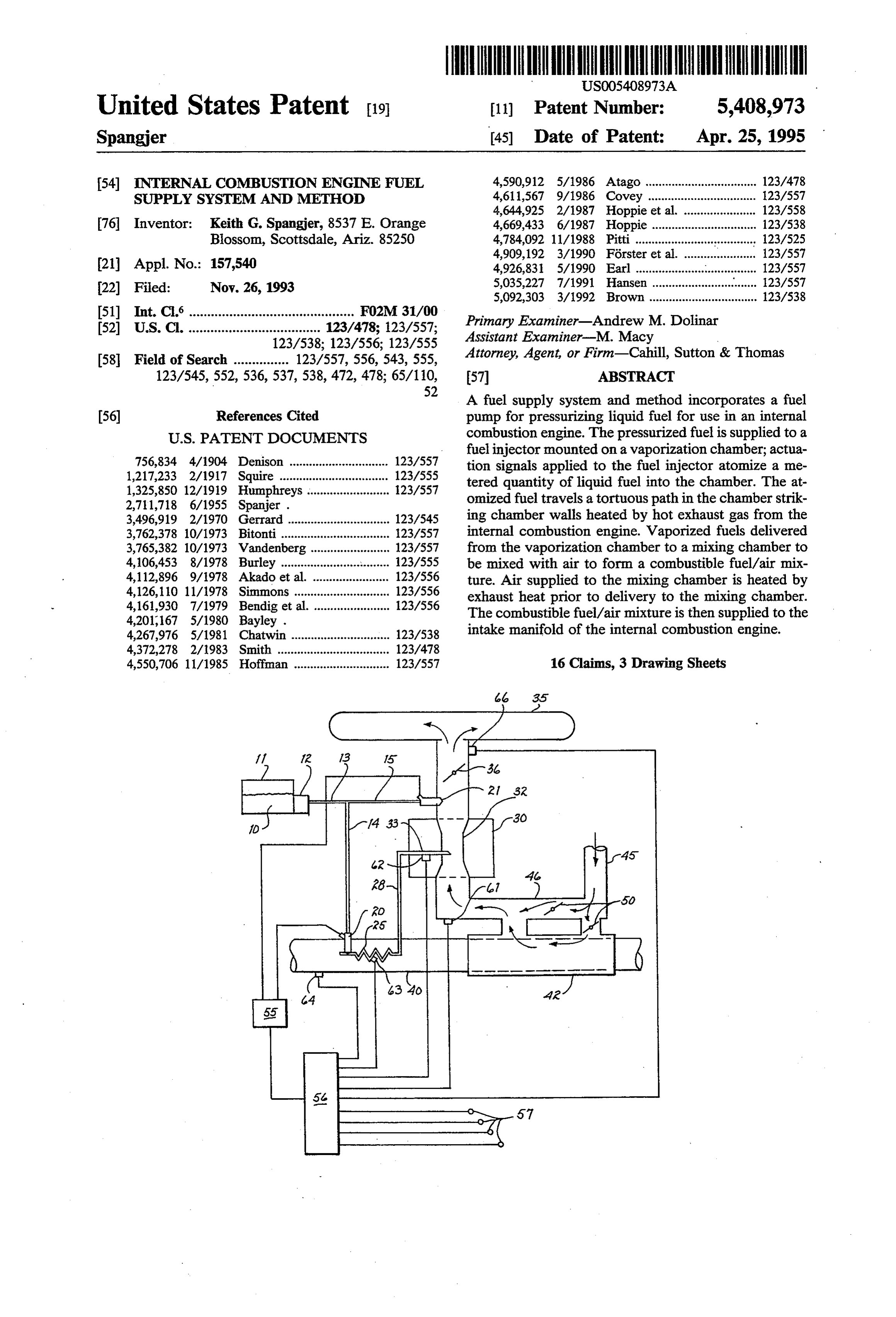
The completely vaporized fuel is then supplied to a maintained at approximately two atmospheres pressure mixing chamber such as a carburetor device where it is to minimize lag in engine response. The fuel/air mixture mixed with incoming air to provide the appropriate is then admitted to intake manifold 35 past throttle fuel/air mixture. The temperature of the incoming air is valve 36. In the embodiment chosen for illustration, the maintained sufficiently high to ensure the vaporized diagram is necessarily schematic to permit a convenient state of the fuel as it is transported from the mixing description of the invention; it will be understood by device to the individual cylinders; thus, the fuel vapor those skilled in the art that the actual arrangement of the mixed with the incoming air is not permitted to cool respective components will depend on the particular sufficiently to create condensation and revert to the engine application and configuration. liquid state. 10 Secondary fuel injector 21 may be positioned to pro BRIEF DESCRIPTION OF THE DRAWINGS vide atomized fuel injection into the incoming air stream during the start up of the engine before the en
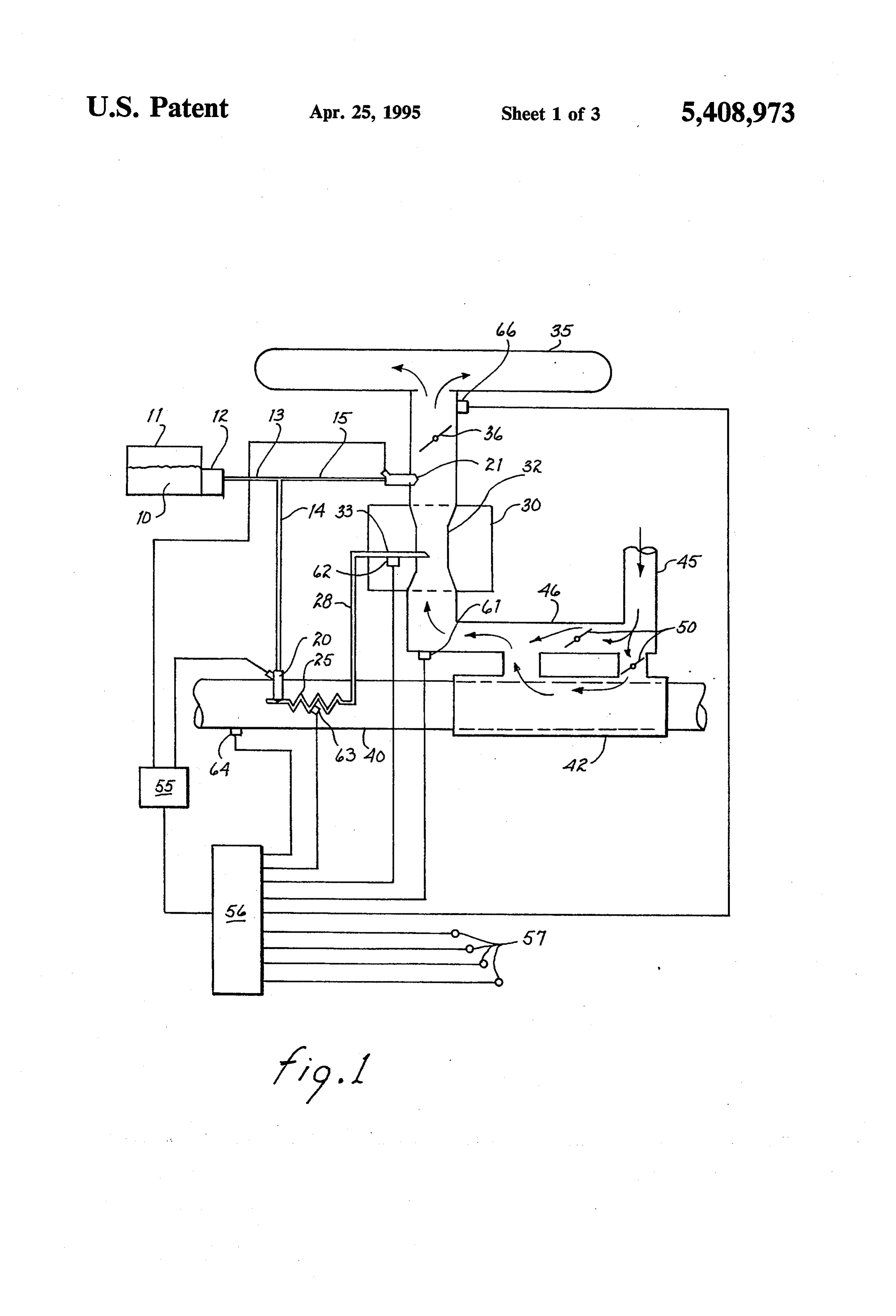
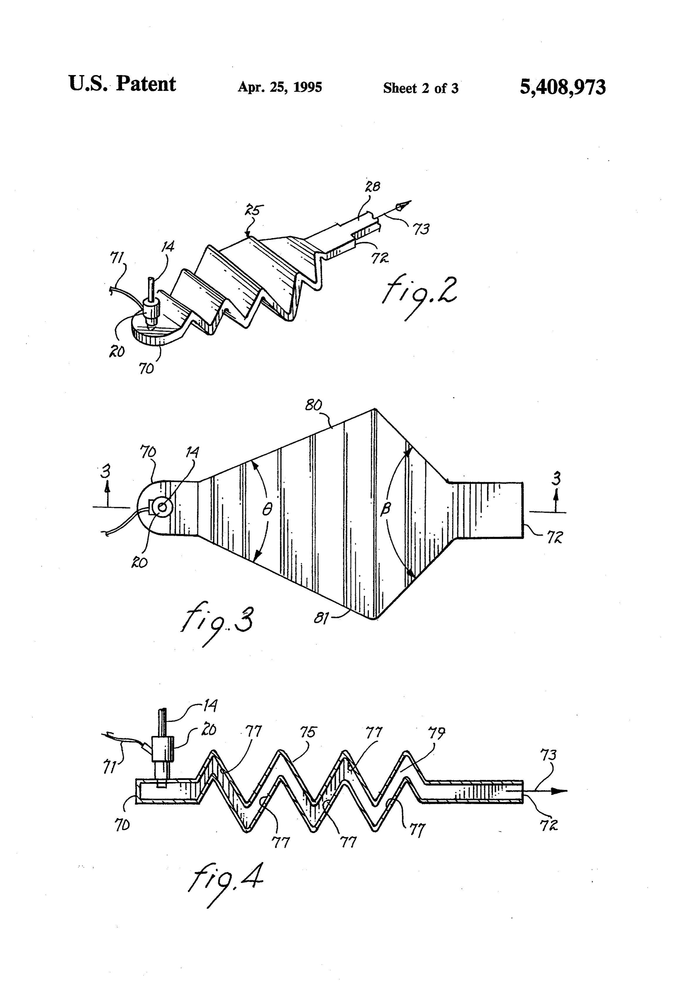
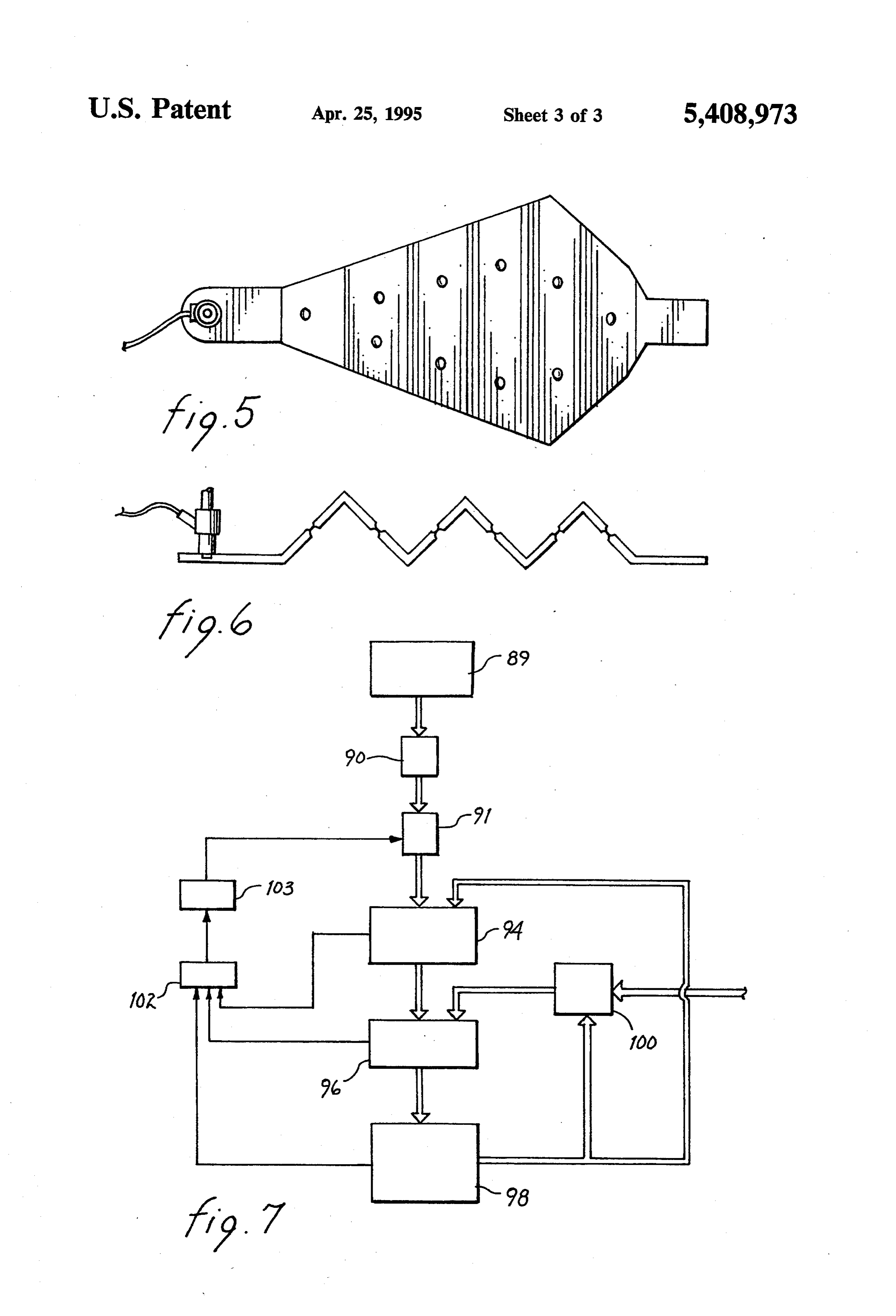
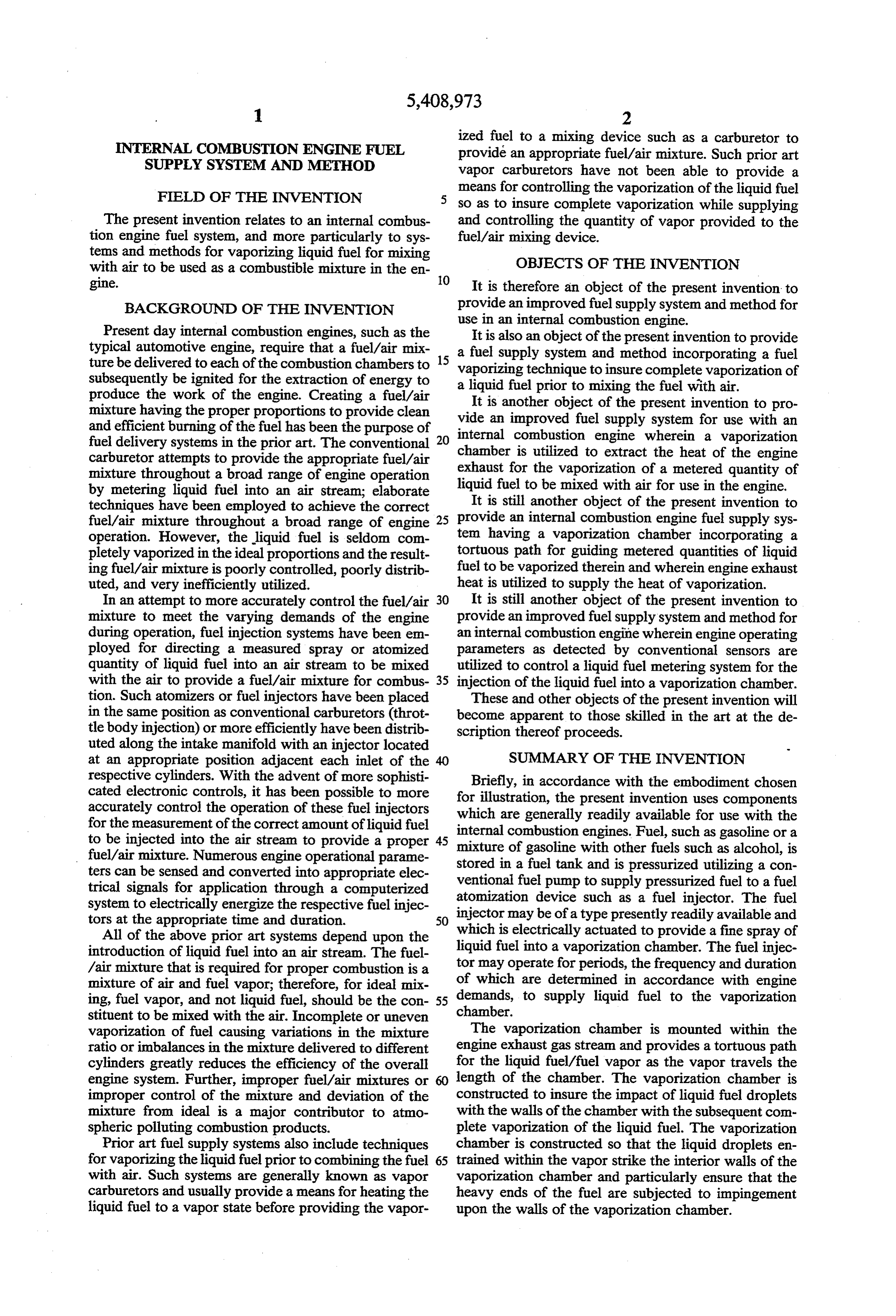
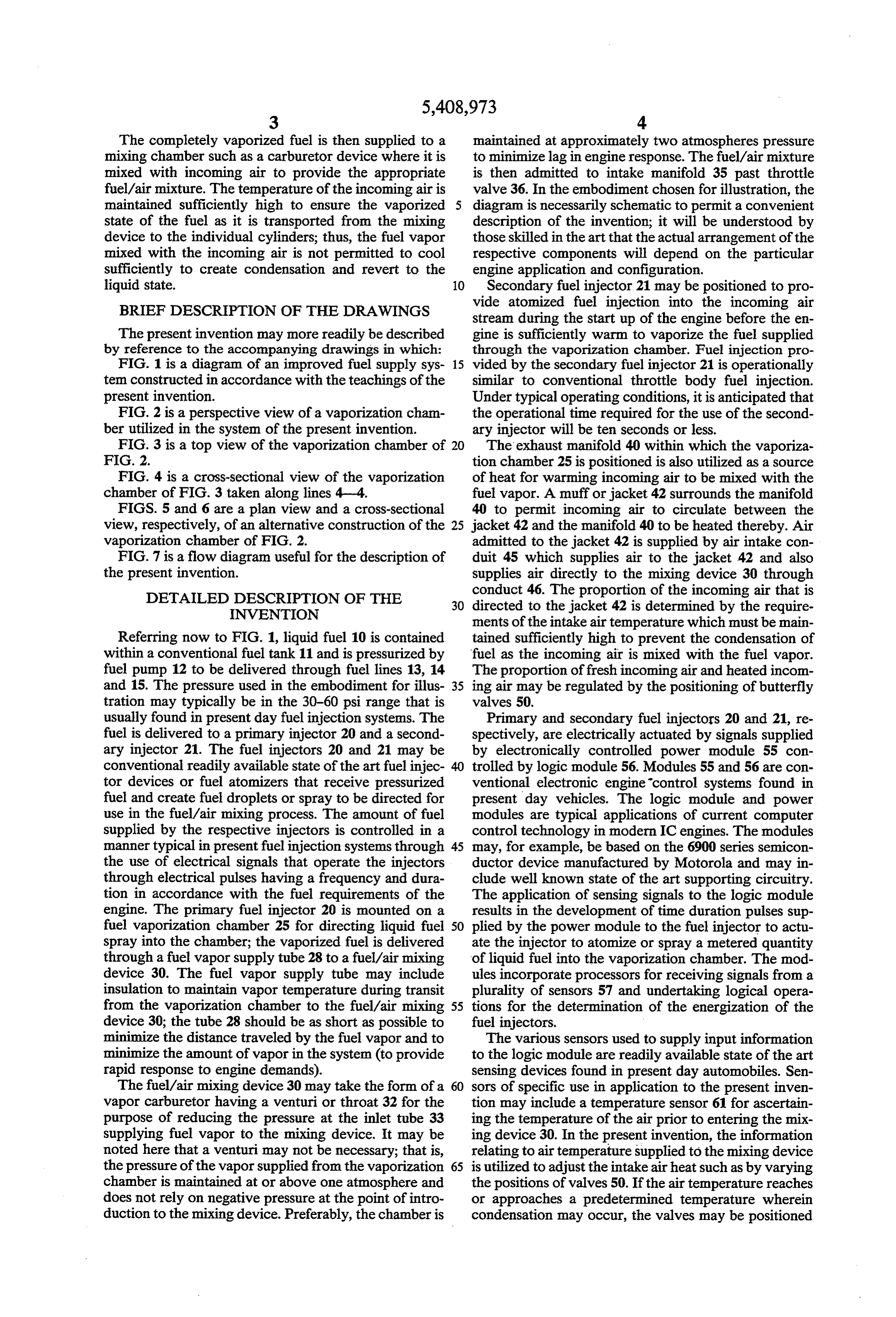
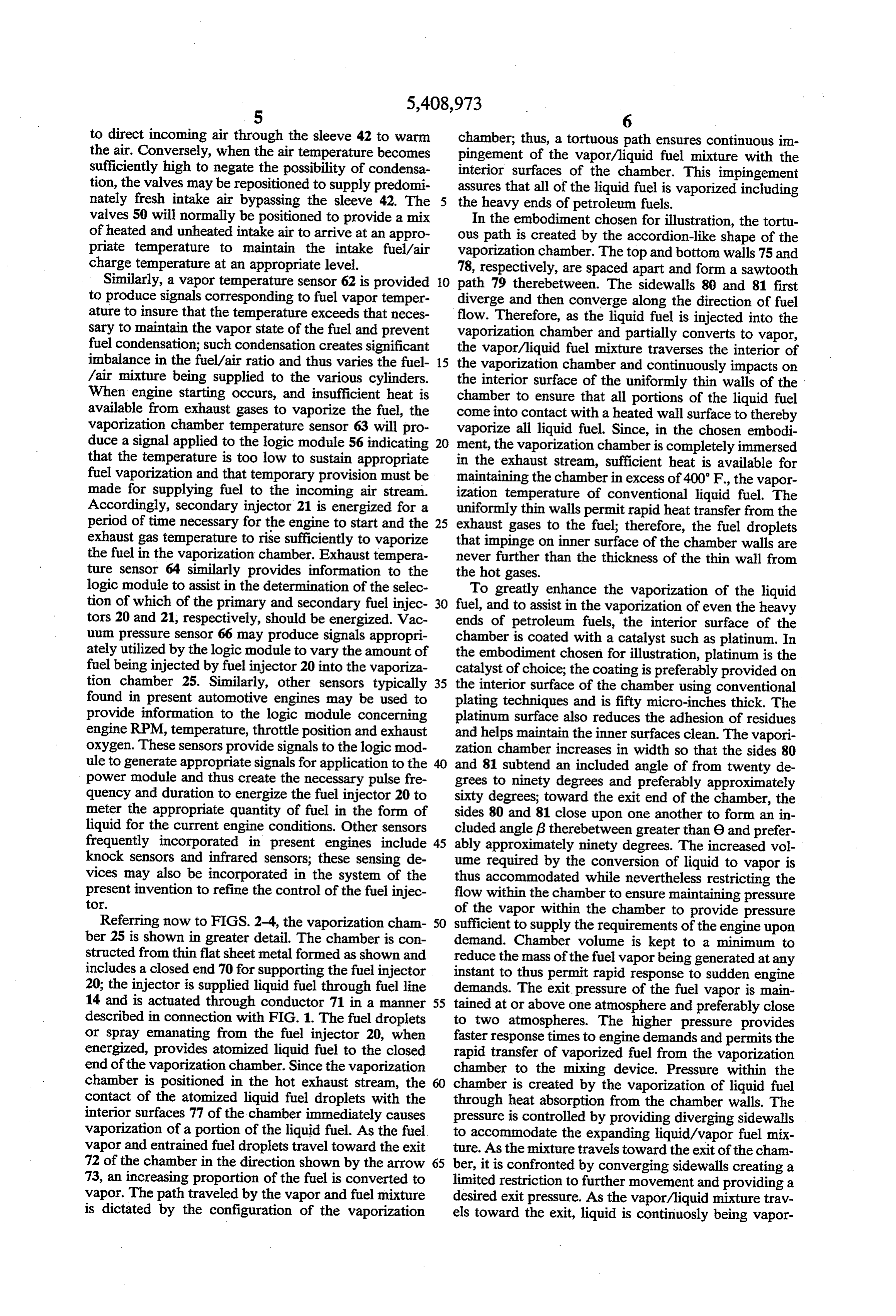
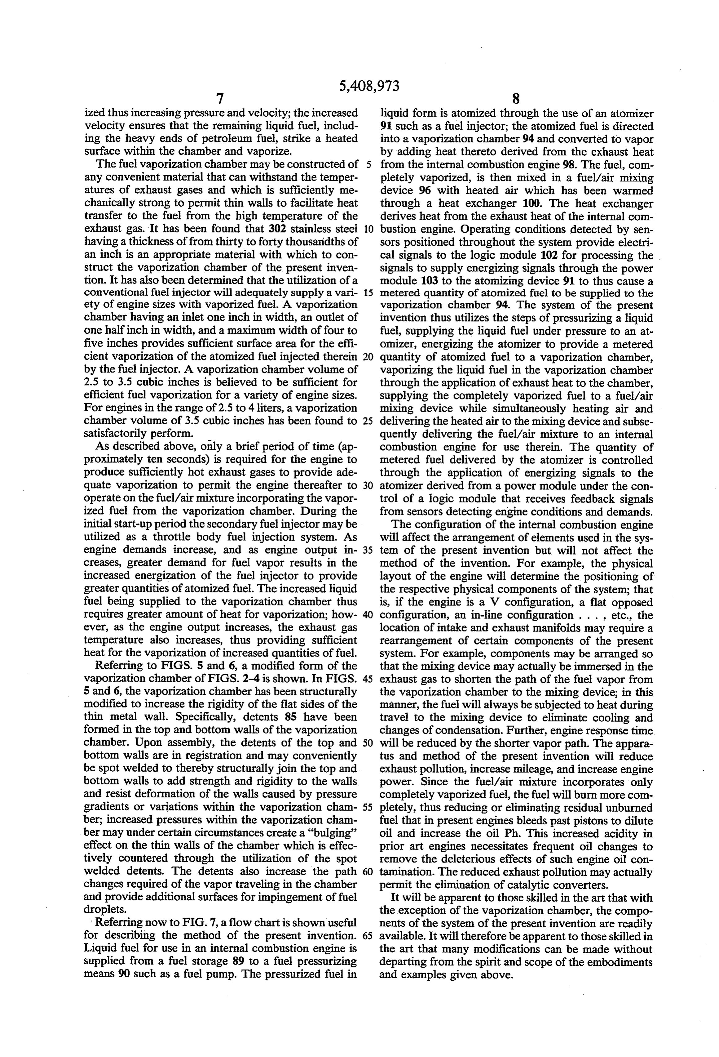
The present invention may more readily be described gine is sufficiently warm to vaporize the fuel supplied by reference to the accompanying drawings in which: through the vaporization chamber. Fuel injection pro FIG. 1 is a diagram of an improved fuel supply sys 15 vided by the secondary fuel injector 21 is operationally tem constructed in accordance with the teachings of the similar to conventional throttle body fuel injection. present invention. Under typical operating conditions, it is anticipated that FIG. 2 is a perspective view of a vaporization cham the operational time required for the use of the second ber utilized in the system of the present invention. ary injector will be ten seconds or less. FIG. 3 is a top view of the vaporization chamber of 20 The exhaust manifold 40 within which the vaporiza FIG. 2. tion chamber 25 is positioned is also utilized as a source FIG. 4 is a cross-sectional view of the vaporization of heat for warming incoming air to be mixed with the chamber of FIG. 3 taken along lines 4-4. fuel vapor. A muff or jacket 42 surrounds the manifold FIGS. 5 and 6 are a plan view and a cross-sectional 40 to permit incoming air to circulate between the view, respectively, of an alternative construction of the 25 jacket 42 and the manifold 40 to be heated thereby. Air vaporization chamber of FIG. 2. admitted to the jacket 42 is supplied by air intake con FIG. 7 is a flow diagram useful for the description of duit 45 which supplies air to the jacket 42 and also the present invention. supplies air directly to the mixing device 30 through DETAILED DESCRIPTION OF THE conduct 46. The proportion of the incoming air that is 30 directed to the jacket 42 is determined by the require
INVENTION
ments of the intake air temperature which must be main
Referring now to FIG. 1, liquid fuel 10 is contained tained sufficiently high to prevent the condensation of within a conventional fuel tank 11 and is pressurized by fuel as the incoming air is mixed with the fuel vapor. fuel pump 12 to be delivered through fuel lines 13, 14 The proportion of fresh incoming air and heated incom and 15. The pressure used in the embodiment for illus 35 ing air may be regulated by the positioning of butterfly tration may typically be in the 30-60 psi range that is valves 50.
usually found in present day fuel injection systems. The Primary and secondary fuel injectors 20 and 21, re fuel is delivered to a primary injector 20 and a second spectively, are electrically actuated by signals supplied ary injector 21. The fuel injectors 20 and 21 may be by electronically controlled power module 55 con conventional readily available state of the art fuel injec trolled by logic module 56. Modules 55 and 56 are con tor devices or fuel atomizers that receive pressurized ventional electronic engine control systems found in fuel and create fuel droplets or spray to be directed for present day vehicles. The logic module and power use in the fuel/air mixing process. The amount of fuel modules are typical applications of current computer supplied by the respective injectors is controlled in a control technology in modern IC engines. The modules manner typical in present fuel injection systems through 45 may, for example, be based on the 6900 series semicon the use of electrical signals that operate the injectors ductor device manufactured by Motorola and may in through electrical pulses having a frequency and dura clude well known state of the art supporting circuitry. tion in accordance with the fuel requirements of the The application of sensing signals to the logic module engine. The primary fuel injector 20 is mounted on a results in the development of time duration pulses sup fuel vaporization chamber 25 for directing liquid fuel 50 plied by the power module to the fuel injector to actu spray into the chamber; the vaporized fuel is delivered ate the injector to atomize or spray a metered quantity through a fuel vapor supply tube 28 to a fuel/air mixing of liquid fuel into the vaporization chamber. The mod device 30. The fuel vapor supply tube may include ules incorporate processors for receiving signals from a insulation to maintain vapor temperature during transit plurality of sensors 57 and undertaking logical opera from the vaporization chamber to the fuel/air mixing 55 tions for the determination of the energization of the device 30; the tube 28 should be as short as possible to fuel injectors.
minimize the distance traveled by the fuel vapor and to The various sensors used to supply input information minimize the amount of vapor in the system (to provide to the logic module are readily available state of the art rapid response to engine demands). sensing devices found in present day automobiles. Sen The fuel/air mixing device 30 may take the form of a sors of specific use in application to the present inven vapor carburetor having a venturi or throat 32 for the tion may include a temperature sensor 61 for ascertain purpose of reducing the pressure at the inlet tube 33 ing the temperature of the air prior to entering the mix supplying fuel vapor to the mixing device. It may be ing device 30. In the present invention, the information noted here that a venturi may not be necessary; that is, relating to air temperature supplied to the mixing device the pressure of the vapor supplied from the vaporization 65 is utilized to adjust the intake air heat such as by varying chamber is maintained at or above one atmosphere and the positions of valves 50. If the air temperature reaches does not rely on negative pressure at the point of intro or approaches a predetermined temperature wherein duction to the mixing device. Preferably, the chamber is condensation may occur, the valves may be positioned
Page 7
to direct incoming air through the sleeve 42 to warm chamber; thus, a tortuous path ensures continuous im the air. Conversely, when the air temperature becomes pingement of the vapor?liquid fuel mixture with the sufficiently high to negate the possibility of condensa interior surfaces of the chamber. This impingement tion, the valves may be repositioned to supply predomi assures that all of the liquid fuel is vaporized including nately fresh intake air bypassing the sleeve 42. The the heavy ends of petroleum fuels.
valves 50 will normally be positioned to provide a mix In the embodiment chosen for illustration, the tortu of heated and unheated intake air to arrive at an appro ous path is created by the accordion-like shape of the priate temperature to maintain the intake fuel/air vaporization chamber. The top and bottom walls 75 and charge temperature at an appropriate level. 78, respectively, are spaced apart and form a sawtooth Similarly, a vapor temperature sensor 62 is provided O path 79 therebetween. The sidewalls 80 and 81 first to produce signals corresponding to fuel vapor temper diverge and then converge along the direction of fuel ature to insure that the temperature exceeds that neces flow. Therefore, as the liquid fuel is injected into the sary to maintain the vapor state of the fuel and prevent vaporization chamber and partially converts to vapor, fuel condensation; such condensation creates significant the vaporyliquid fuel mixture traverses the interior of imbalance in the fuel/air ratio and thus varies the fuel 15 the vaporization chamber and continuously impacts on /air mixture being supplied to the various cylinders. the interior surface of the uniformly thin walls of the When engine starting occurs, and insufficient heat is chamber to ensure that all portions of the liquid fuel available from exhaust gases to vaporize the fuel, the come into contact with a heated wall surface to thereby vaporization chamber temperature sensor 63 will pro vaporize all liquid fuel. Since, in the chosen embodi duce a signal applied to the logic module 56 indicating 20 ment, the vaporization chamber is completely immersed that the temperature is too low to sustain appropriate in the exhaust stream, sufficient heat is available for fuel vaporization and that temporary provision must be maintaining the chamber in excess of 400°F., the vapor made for supplying fuel to the incoming air stream. ization temperature of conventional liquid fuel. The Accordingly, secondary injector 21 is energized for a uniformly thin walls permit rapid heat transfer from the period of time necessary for the engine to start and the 25 exhaust gases to the fuel; therefore, the fuel droplets exhaust gas temperature to rise sufficiently to vaporize that impinge on inner surface of the chamber walls are the fuel in the vaporization chamber. Exhaust tempera never further than the thickness of the thin wall from ture sensor 64 similarly provides information to the the hot gases.
logic module to assist in the determination of the selec To greatly enhance the vaporization of the liquid tion of which of the primary and secondary fuel injec 30 fuel, and to assist in the vaporization of even the heavy tors 20 and 21, respectively, should be energized. Vac ends of petroleum fuels, the interior surface of the uum pressure sensor 66 may produce signals appropri chamber is coated with a catalyst such as platinum. In ately utilized by the logic module to vary the amount of the embodiment chosen for illustration, platinum is the fuel being injected by fuel injector 20 into the vaporiza catalyst of choice; the coating is preferably provided on tion chamber 25. Similarly, other sensors typically 35 the interior surface of the chamber using conventional found in present automotive engines may be used to plating techniques and is fifty micro-inches thick. The provide information to the logic module concerning platinum surface also reduces the adhesion of residues engine RPM, temperature, throttle position and exhaust and helps maintain the inner surfaces clean. The vapori oxygen. These sensors provide signals to the logic mod zation chamber increases in width so that the sides 80 ule to generate appropriate signals for application to the and 81 subtend an included angle of from twenty de power module and thus create the necessary pulse fre grees to ninety degrees and preferably approximately quency and duration to energize the fuel injector 20 to sixty degrees; toward the exit end of the chamber, the meter the appropriate quantity of fuel in the form of sides 80 and 81 close upon one another to form an in liquid for the current engine conditions. Other sensors cluded angle (3 therebetween greater than 6 and prefer frequently incorporated in present engines include 45 ably approximately ninety degrees. The increased vol knock sensors and infrared sensors; these sensing de ume required by the conversion of liquid to vapor is vices may also be incorporated in the system of the thus accommodated while nevertheless restricting the present invention to refine the control of the fuel injec flow within the chamber to ensure maintaining pressure tor.
of the vapor within the chamber to provide pressure
Referring now to FIGS. 2-4, the vaporization cham 50 sufficient to supply the requirements of the engine upon ber 25 is shown in greater detail. The chamber is con demand. Chamber volume is kept to a minimum to structed from thin flat sheet metal formed as shown and reduce the mass of the fuel vapor being generated at any includes a closed end 70 for supporting the fuel injector instant to thus permit rapid response to sudden engine 20; the injector is supplied liquid fuel through fuel line demands. The exit pressure of the fuel vapor is main 14 and is actuated through conductor 71 in a manner 55 tained at or above one atmosphere and preferably close described in connection with FIG. 1. The fuel droplets to two atmospheres. The higher pressure provides or spray emanating from the fuel injector 20, when faster response times to engine demands and permits the energized, provides atomized liquid fuel to the closed rapid transfer of vaporized fuel from the vaporization end of the vaporization chamber. Since the vaporization chamber to the mixing device. Pressure within the chamber is positioned in the hot exhaust stream, the chamber is created by the vaporization of liquid fuel contact of the atomized liquid fuel droplets with the through heat absorption from the chamber walls. The interior surfaces 77 of the chamber immediately causes pressure is controlled by providing diverging sidewalls vaporization of a portion of the liquid fuel. As the fuel to accommodate the expanding liquid/vapor fuel mix vapor and entrained fuel droplets travel toward the exit ture. As the mixture travels toward the exit of the cham 72 of the chamber in the direction shown by the arrow 65 ber, it is confronted by converging sidewalls creating a 73, an increasing proportion of the fuel is converted to limited restriction to further movement and providing a vapor. The path traveled by the vapor and fuel mixture desired exit pressure. As the vapor/liquid mixture trav is dictated by the configuration of the vaporization els toward the exit, liquid is continuosly being vapor
Page 8
ized thus increasing pressure and velocity; the increased liquid form is atomized through the use of an atomizer velocity ensures that the remaining liquid fuel, includ 91 such as a fuel injector; the atomized fuel is directed ing the heavy ends of petroleum fuel, strike a heated into a vaporization chamber 94 and converted to vapor surface within the chamber and vaporize. by adding heat thereto derived from the exhaust heat The fuel vaporization chamber may be constructed of 5 from the internal combustion engine 98. The fuel, com any convenient material that can withstand the temper pletely vaporized, is then mixed in a fuel/air mixing atures of exhaust gases and which is sufficiently me device 96 with heated air which has been warmed chanically strong to permit thin walls to facilitate heat through a heat exchanger 100. The heat exchanger transfer to the fuel from the high temperature of the derives heat from the exhaust heat of the internal com exhaust gas. It has been found that 302 stainless steel 10 bustion engine. Operating conditions detected by sen having a thickness of from thirty to forty thousandths of sors positioned throughout the system provide electri an inch is an appropriate material with which to con cal signals to the logic module 102 for processing the struct the vaporization chamber of the present inven signals to supply energizing signals through the power tion. It has also been determined that the utilization of a module 103 to the atomizing device 91 to thus cause a conventional fuel injector will adequately supply a vari 15 metered quantity of atomized fuel to be supplied to the ety of engine sizes with vaporized fuel. A vaporization vaporization chamber 94. The system of the present chamber having an inlet one inch in width, an outlet of invention thus utilizes the steps of pressurizing a liquid one halfinch in width, and a maximum width of four to fuel, supplying the liquid fuel under pressure to an at five inches provides sufficient surface area for the effi omizer, energizing the atomizer to provide a metered cient vaporization of the atomized fuel injected therein 20 quantity of atomized fuel to a vaporization chamber, by the fuel injector. A vaporization chamber volume of vaporizing the liquid fuel in the vaporization chamber 2.5 to 3.5 cubic inches is believed to be sufficient for through the application of exhaust heat to the chamber, efficient fuel vaporization for a variety of engine sizes. supplying the completely vaporized fuel to a fuel/air For engines in the range of 2.5 to 4 liters, a vaporization mixing device while simultaneously heating air and chamber volume of 3.5 cubic inches has been found to 25 delivering the heated air to the mixing device and subse satisfactorily perform. quently delivering the fuel/air mixture to an internal As described above, only a brief period of time (ap combustion engine for use therein. The quantity of proximately ten seconds) is required for the engine to metered fuel delivered by the atomizer is controlled produce sufficiently hot exhaust gases to provide ade through the application of energizing signals to the quate vaporization to permit the engine thereafter to 30 atomizer derived from a power module under the con operate on the fuel/air mixture incorporating the vapor trol of a logic module that receives feedback signals ized fuel from the vaporization chamber. During the from sensors detecting engine conditions and demands. initial start-up period the secondary fuel injector may be The configuration of the internal combustion engine utilized as a throttle body fuel injection system. As will affect the arrangement of elements used in the sys engine demands increase, and as engine output in 35 tem of the present invention but will not affect the creases, greater demand for fuel vapor results in the method of the invention. For example, the physical increased energization of the fuel injector to provide layout of the engine will determine the positioning of greater quantities of atomized fuel. The increased liquid the respective physical components of the system; that fuel being supplied to the vaporization chamber thus is, if the engine is a V configuration, a flat opposed requires greater amount of heat for vaporization; how configuration, an in-line configuration . . . , etc., the ever, as the engine output increases, the exhaust gas location of intake and exhaust manifolds may require a temperature also increases, thus providing sufficient rearrangement of certain components of the present heat for the vaporization of increased quantities of fuel. system. For example, components may be arranged so Referring to FIGS. 5 and 6, a modified form of the that the mixing device may actually be immersed in the vaporization chamber of FIGS. 2-4 is shown. In FIGS. 45 exhaust gas to shorten the path of the fuel vapor from 5 and 6, the vaporization chamber has been structurally the vaporization chamber to the mixing device; in this modified to increase the rigidity of the flat sides of the manner, the fuel will always be subjected to heat during thin metal wall. Specifically, detents 85 have been travel to the mixing device to eliminate cooling and formed in the top and bottom walls of the vaporization changes of condensation. Further, engine response time chamber. Upon assembly, the detents of the top and 50 will be reduced by the shorter vapor path. The appara bottom walls are in registration and may conveniently tus and method of the present invention will reduce be spot welded to thereby structurally join the top and exhaust pollution, increase mileage, and increase engine bottom walls to add strength and rigidity to the walls power. Since the fuel/air mixture incorporates only and resist deformation of the walls caused by pressure completely vaporized fuel, the fuel will burn more com gradients or variations within the vaporization cham 55 pletely, thus reducing or eliminating residual unburned ber; increased pressures within the vaporization cham fuel that in present engines bleeds past pistons to dilute ber may under certain circumstances create a "bulging' oil and increase the oil Ph. This increased acidity in effect on the thin walls of the chamber which is effec prior art engines necessitates frequent oil changes to tively countered through the utilization of the spot remove the deleterious effects of such engine oil con welded detents. The detents also increase the path 60 tamination. The reduced exhaust pollution may actually changes required of the vapor traveling in the chamber permit the elimination of catalytic converters. and provide additional surfaces for impingement of fuel It will be apparent to those skilled in the art that with droplets. the exception of the vaporization chamber, the compo Referring now to FIG. 7, a flow chart is shown useful nents of the system of the present invention are readily for describing the method of the present invention. 65 available. It will therefore be apparent to those skilled in Liquid fuel for use in an internal combustion engine is the art that many modifications can be made without supplied from a fuel storage 89 to a fuel pressurizing departing from the spirit and scope of the embodiments means 90 such as a fuel pump. The pressurized fuel in and examples given above.
Page 9
What is claimed is: ness to facilitate heat transfer from the hot exhaust gases 1. In an internal combustion engine adapted to oper to the fuel in the chamber.
ate using a vaporized fuel and air mixture and having an 7. The combination set forth in claim 6 wherein said intake manifold for supplying said mixture to a combus vaporization chamber includes spaced apart top and tion chamber therein, said engine producing hot exhaust bottom walls formed to provide a sawtooth path there gases, an improved fuel supply system comprising: between for fuel and vapor therein. (a) storage means for storing liquid fuel; 8. The combination set forth in claim 7 wherein said (b) fuel pressuring means connected to said storage vaporization chamber includes sidewalls extending be means for pressurizing and delivering fuel from tween said top and bottom walls, and wherein said said storage means; 10 sidewalls diverge in the direction of vapor flow at a (c) a vaporization chamber positioned within said predetermined angle and then converge at a second exhaust gases for vaporizing liquid fuel; predetermined angle.
(d) a liquid fuel atomizing means connected to re 9. The combination set forth in claim 4 wherein said ceive pressurized fuel from said fuel pressurizing vaporization chamber includes interior surfaces having means and positioned to deliver a measured quan 15 a layer of catalytic material thereon. tity of atomized liquid fuel into said vaporization 10. The combination set forth in claim 9 wherein said chamber; catalytic material is platinum plated on said surfaces. (e) fuel/air mixing means connected to receive fuel sidewalls11. The combination set forth in claim 8 wherein the vapor from said vaporization chamber, said mixing 20 diverge at an angle from twenty degrees to ninety degrees and then converge at an angle greater means also connected to receive air for mixing with than said fuel vapor; and the angle of divergence.
(f) means connecting said fuel/air mixing means to sidewalls 12. The combination set forth in claim 8 wherein the said internal combustion engine intake manifold for diverge at an angle of sixty degrees and then delivering fuel/air mixture to the combustion 25 converge 13. In an at an angle of ninety degrees.
internal combustion engine adapted to oper chamber thereof.
2. The combination set forth in claim 1 wherein said ate using a vaporized fuel and air mixture and having an fuel atomizer is an electrically actuated fuel injector. intake manifold for supplying said mixture to a combus 3. The combination set forth in claim 2 including a tion gases, chamber therein, said engine producing hot exhaust an improved fuel supply system, comprising:
plurality of sensors for detecting engine operating con ditions and generating electrical signals in response 30 (a) storage means for storing liquid fuel; (b) fuel pressuring means connected to said storage thereto, means connected to said sensors responsive to means for pressurizing and delivering fuel from said signals for generating fuel injector actuating sig said storage means;
nals, and means connecting said actuating signals to said (c) a vaporization chamber positioned within said fuel injector for actuating said injector to deliver a 35 exhaust gases for vaporizing liquid fuel; metered quantity of atomized fuel. (d) a liquid fuel atomizing means connected to re 4. In an internal combustion engine adapted to oper ceive pressurized fuel from said fuel pressurizing ate using a vaporized fuel and air mixture and having an means and positioned to deliver a measured quan intake manifold for supplying said mixture to a combus tity of atomized liquid fuel into said vaporization tion chamber therein, said engine producing hot exhaust chamber;
gases, an improved fuel supply system comprising: (e) fuel/air mixing means connected to receive fuel (a) storage means for storing liquid fuel; vapor from said vaporization chamber and to re (b) fuel pressuring means connected to said storage ceive warmed air for mixing with said fuel vapor; means for pressurizing and delivering fuel from (f) air warming means connected to said fuel/air mix said storage means; 45 ing means for receiving outside air and directing (c) a vaporization chamber for vaporizing liquid fuel, said air to a heat exchanger for extracting heat said chamber immersed in said hot exhaust gases from said exhaust gas and warming said air for for extracting heat from said gases for vaporizing delivery to said fuel/air mixing means; and liquid fuel in said chamber; (g) means connecting said fuel/air mixing means to (d) a liquid fuel atomizing means connected to re 50 said internal combustion engine intake manifold for ceive pressurized fuel from said fuel pressurizing delivering fuel/air mixture to the combustion means and positioned to deliver atomized liquid chamber thereof.
fuel into said vaporization chamber; 14. The combination set forth in claim 13 including (e) fuel/air mixing means connected to receive fuel means responsive to the temperature of air supplied to vapor from said vaporization chamber, said mixing 55 said fuel/air mixing means for controlling the propor means also connected to receive air for mixing with tions of warmed and unwarmed air for delivery to said said fuel vapor; and mixing means.
(f) means connecting said fuel/air mixing means to 15. A method for supplying fuel to an internal com said internal combustion engine intake manifold for bustion engine adapted to operate using a vaporized fuel delivering fuel/air mixture to the combustion and air mixture and having an intake manifold for sup chamber thereof. plying said mixture to a combustion chamber therein, 5. The combination set forth in claim 4 wherein said said engine producing hot exhaust gases, comprising the fuel atomizing means is mounted on said vaporization steps:
chamber. (a) pressurizing liquid fuel; 6. The combination set forth in claim 4 wherein said 65 (b) atomizing the pressurized liquid fuel; vaporization chamber is formed to provide a tortuous (c) directing a metered quantity of said atomized fuel path for fuel traveling therethrough and wherein the into a vaporization chamber positioned within said chamber is formed having thin walls of uniform thick hot exhaust gases;
Page 10
(d) vaporizing said atomized fuel in said vaporization (b) atomizing the pressurized liquid fuel; chamber by directing said hot exhaust gases into (c) directing a metered quantity of said atomized fuel contact with said vaporization chamber; into a vaporization chamber positioned within said (e) mixing the resulting vaporized fuel with air to hot exhaust gases;
form a fuel/air mixture; and (d) vaporizing said atomized fuel in said vaporization (f) delivering said fuel/air mixture to the intake mani chamber by directing said hot exhaust gases into fold of said internal combustion engine. contact with said vaporization chamber while si 16. A method for supplying fuel to an internal com multaneously heating air with heat extracted from bustion engine adapted to operate using a vaporized fuel said hot exhaust gases; and air mixture and having an intake manifold for sup 10 (e) mixing the resulting vaporized fuel with said plying said mixture to a combustion chamber therein, heated air to form a fuel/air mixture; and said engine producing hot exhaust gases, comprising the (f) delivering said fuel/air mixture to the intake mani steps: fold of said internal combustion engine. (a) pressurizing liquid fuel; k k 2 k e
Provenance
- Collection
- Cited prior art
- Original PDF
- patentimages.storage.googleapis.com →
- Filed
- 1993-11-26
- Pages
- 10
- Method
- pdftotext (the PDF's own text layer) + pdftoppm 300dpi page scans
- Source
- Google Patents bibliographic record
- Granted
- 1995-04-25
- Inventors
- Keith G. Spangjer
- Transcribed from
- patentimages.storage.googleapis.com →