patent · US3608660
Smog-free automobile and method of operating same
28 September 1971
Page 1 — bibliographic record
United States Patent (11) 3,608,660 (72) inventors Richard D. Smith 2,487, 176 1 1/1949 Pitt et al....................... 55/(ET) Palo Alto; 2,496,623 2/950 Fragale......................... 123/119 (E) X Dale A. Furlong, Menlo Park, both of Calif. 2,623,725 12/1952 Sands........................... 137.1513.7 X
(22 Filed Feb. 3, 1969 3,240,644 3/1966 Wolff........................... 220/3 X (45) Patented Sept. 28, 1971 FOREIGN PATENTS (73) Assignee Combustion Power Company, Inc. 571,263 8/1945 Great Britain................ 280/5 A Palo Alto, Calif. Primary Examiner-Benjamin Hersh
Assistant Examiner-Milton L. Smith 54 SMOG-FREE AUTOMOBILE AND METHOD OF Attorney-Charles B. Smith
OPERATING SAME
9 Claims, 19 Drawing Figs.
(52) U.S. Cl........................................................ 180/54B, ABSTRACT: A smog-free automobile is described burning 55/DIG. 30, 123/1 A, 12312.5 C, 137/513.7, 280/5 fuel and substantially pure oxygen and spray water cooling the A cylinder walls and pistons during exhaust. A dual combustion 5ll int. Cl......................................................... B60k 15/08 system is utilized, Otto cycle for cruise power and diesel cycle (50) Field of Search............................................ 180/54, 1; above cruise power, and water is recovered from the exhaust. 280/5A; 296/1; 114/16 (.35); 294/1 (55); 123/19 The fuel can be pure hydrogen or liquid gasoline. With liquid E, 1 A, 25.2; 13715, 13.7;55/ET gasoline, oxygen input atomizes the gasoline and with hydrogen fuel both hydrogen and oxygen can be produced by (56) References Cited electrolysis, ideally utilizing nuclear electric generation for a UNITED STATES PATENTS complete smog-free system operation. Gaseous material is 1,196,643 8/1916 Bedford et al................ 180/54 stored in a plurality of high-pressure vessels and in the case of 1,233,951 7/1917 Alder........................... 123/25 (.2) UX hydrogen fuel with the pressure vessels at the rear of the auto. 1496,951 6 1924 Shinkle......................... 12311 19 EUX Separate sets of vessels are provided for cruise power supply 1,788,358 1/1931 Goerg..... 137.1513.7 and above cruise power supply and valving is provided to use the opposite set of tanks in case fuel for one operation is ex 2, 183,674 12/1939 Erren........................ 123/119 EUX hausted.
Page 2
Drawing sheet — no readable text.
Page 3
Drawing sheet — no readable text.
Page 4
Drawing sheet — no readable text.
Page 5
PATENTED SEP2897 3,608,660
SHEET OF 6
FIG.5 to lysos: -OXY GEN
OPERATION
GASOLINE-OXY GEN
--MAXIMUM POWER CYCLE
ENGINE HORSEPOWER 3000 RPM.
y-CRUISE CYCLE
isot
zo 3840°For NVENTORS
RCHARD D. SMITH
s i.S. BAEA" trix
CYLNDER WOLUME FT ATTORNEYS
Page 6
Drawing sheet — no readable text.
Page 7
Drawing sheet — no readable text.
Page 8
SMOG-FREE AUTOMOBILE AND METHOD OF for water cooling the cylinder and pistons during exhaust. A
OPERATING SAME
The present invention relates in general to smog-free au water isand feature advantage of the invention lies in the fact that the major combustion product of the gasoline or tomobiles and methods of operating same. hydrogen fuel with pure oxygen so that cooling fluids are pro Control of air pollution is one of the most pressing problems vided without requiring excessive cooling fluid storage in the facing industrial and population centers around the world car. The cooling fluids are regenerated during operation. today. The city dweller is being gradually poisoned with lethal doses of carbon monoxide, unburned hydrocarbons, and tion, the hydrogenwith
In accordance still another aspect of the present inven fuel and the pure oxygen for combustion of nitrogen oxides that pour from millions of exhausts from pas hydrogen are produced by the electrolysis of water. In elec senger cars and trucks that crowd the streets and highways in 10 trolysis pure oxygen and hydrogen ever increasing numbers. Somewhere be 40 percent and 60 ratio required for combustion suchare produced in the precise that only water is formed.
percent of the air pollution is caused by various forms of This makes an efficient and easily operated pollution free motor vehicle exhaust products.
The three major approaches currently being pursued to pro system.
In accordance with still another aspect of the present inven vide a pollution-free car are: (1) elimination of emissions from 15 tion, air-breathing internal combustion engines by means of cata ygen and electrolysis of water for the production of the pure ox lytic filters, fuel additives, engine design, etc; (2development hydrogen for combustion in the smog-free car is ac of an external combustion engine (gas turbine, Stirling engine, complished utilizing nuclear electric generation for accom plishing electrolysis of water. In this system, from the electric steam engine) to replace the current internal combustion en generation through the water electrolysis and through the gine; and (3) development of an electric car to replace current 20 cats. combustion of hydrogen aid oxygen in the internal com The first approach is being vigorously pursued by automo bustion engine, no air pollutants are produced. tive manufacturers and major oil companies because, if suc In accordance with still another aspect of the present inven cessful, it would provide the minimum change to the automo 25 tion where liquid gasoline is utilized as the fuel for the engine, bile as we know it today. Difficult technical problems are an the liquid gasoline is introduced in a stream into the engine ticipated and long-term laboratory research programs are in cylinder and the stream is atomized by the oxygen directed progress to find a technical breakthrough. One of the most dif into the cylinder for combustion. This operation and construc ficult problems is to eliminate the oxides of nitrogen. tion promote fast and uniform combustion. The external combustion engines under consideration 30 In accordance with still another aspect of the present inven require compromises in performance, convenience, or econo tion gaseous material for engine operation is stored in a plu my compared to current automobiles. They will be expensive rality of high pressure tanks whereby the high-pressure gase to develop and will require drastic changes in the production ous material is not only economically stored but also safely tooling of the major automobile manufacturers. More impor stored. In the event one of the high-pressure tanks or any of tantly, however, they are not completely pollution-free. the fluid conduits develops a leak, the other fluid tanks do not Of the three approaches, the electric car is the only one 35 avoided.
give up their stored material and danger of fire or explosion is which is completely pollution-free. Unfortunately, it is also the approach which requires the most research in order to provide In accordance with still another aspect of the present inven car that meets today's standards of performance, comfort, and tion substantially every storage tank of the plurality of storage convenience. tanks includes valve means preventing the rapid gaseous flow Broadly stated, the present invention, to be described in 40 therefrom and a bleed valve permitting slow gaseous bleed greater detail below, is directed to a smog-free internal com from the tank whereby when a tank or manifold is ruptured, bustion engine and automobile therefor and method of operat only a small amount of gaseous material is allowed to escape ing same wherein the engine includes at least one cylinder, a while the remaining gaseous material is slowly vented to per piston reciprocating in the cylinder, and inlet ports and an ex 45 mit repair of the system.
haust port opened and closed cyclically as the piston In accordance with still another aspect of the present inven reciprocates. The inlet ports include a fuel supply inlet, an tion, the storage tanks for storing he high pressure materials inlet for substantially pure oxygen, and an inlet for water. include a metal liner having a cylindrical main body portion Steps and means are provided for supplying controlled and a cylinder wrap of fiberglass around the main body por amounts of fuel and oxygen to the cylinder for substantially 50 tion wherein the metal liner provides strong support against complete combustion of fuel therein and water spraying the longitudinal loads and reasonable support against hoop cylinder and piston during the exhaust cycle. The engine burns stresses and the high strength glass fibers provide the necessa either liquid gasoline or gaseous hydrogen with oxygen. - ry hoop stresses without the weight of metal to produce the in accordance with this invention, an engine is provided equivalent hoop stresses. With this construction, in the event a which is completely smog-free. With hydrogen fuel, the only 55 pressure vessel is fractured due to accident, the fiberglass product of combustion is water and with liquid gasoline, the winding retains the integrity of the pressure vessel while allow products of combustion are water, carbon dioxide and other ing the gaseous materials to escape.
nonpollutants. Other objects and advantages of this invention will become The engine is produced with existing manufacturing apparent when reading the following description and referring technology and achieves current standards for performance, 60 to the accompanying drawing in which similar characters of convenience, and economy. No unusual starting or warmup reference represent corresponding parts in each of the several problems are introduced and periodic maintenance remains views.
unchanged. Once in production, the car will cost about the In the drawings:
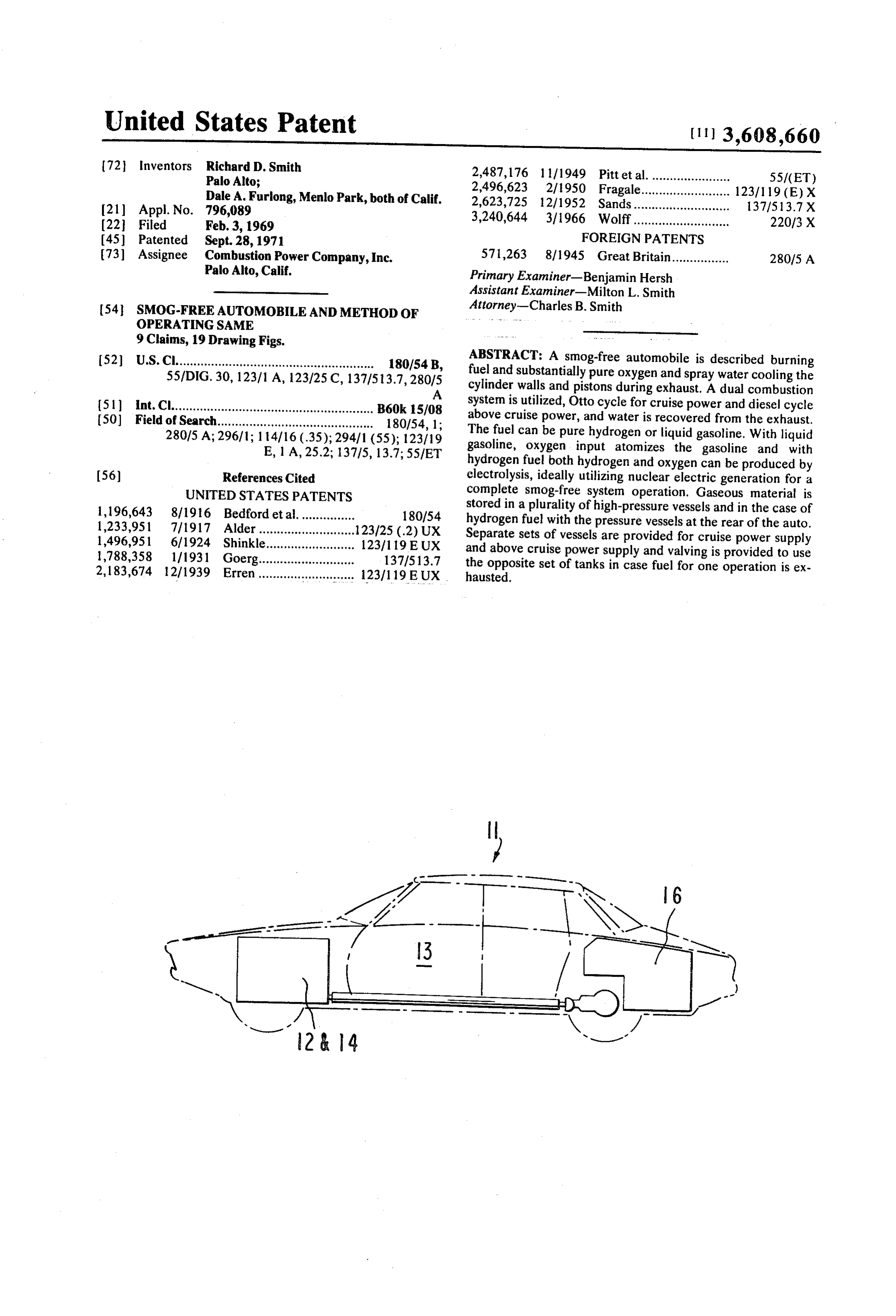
same as a conventional gasoline engine family car and trips to FIG. 1 is a schematic view partially in block diagram form the gas station will be of equivalent frequency and cost. 65 and partially in plan schematically illustrating certain aspects In accordance with another aspect of the present invention, of the present invention.
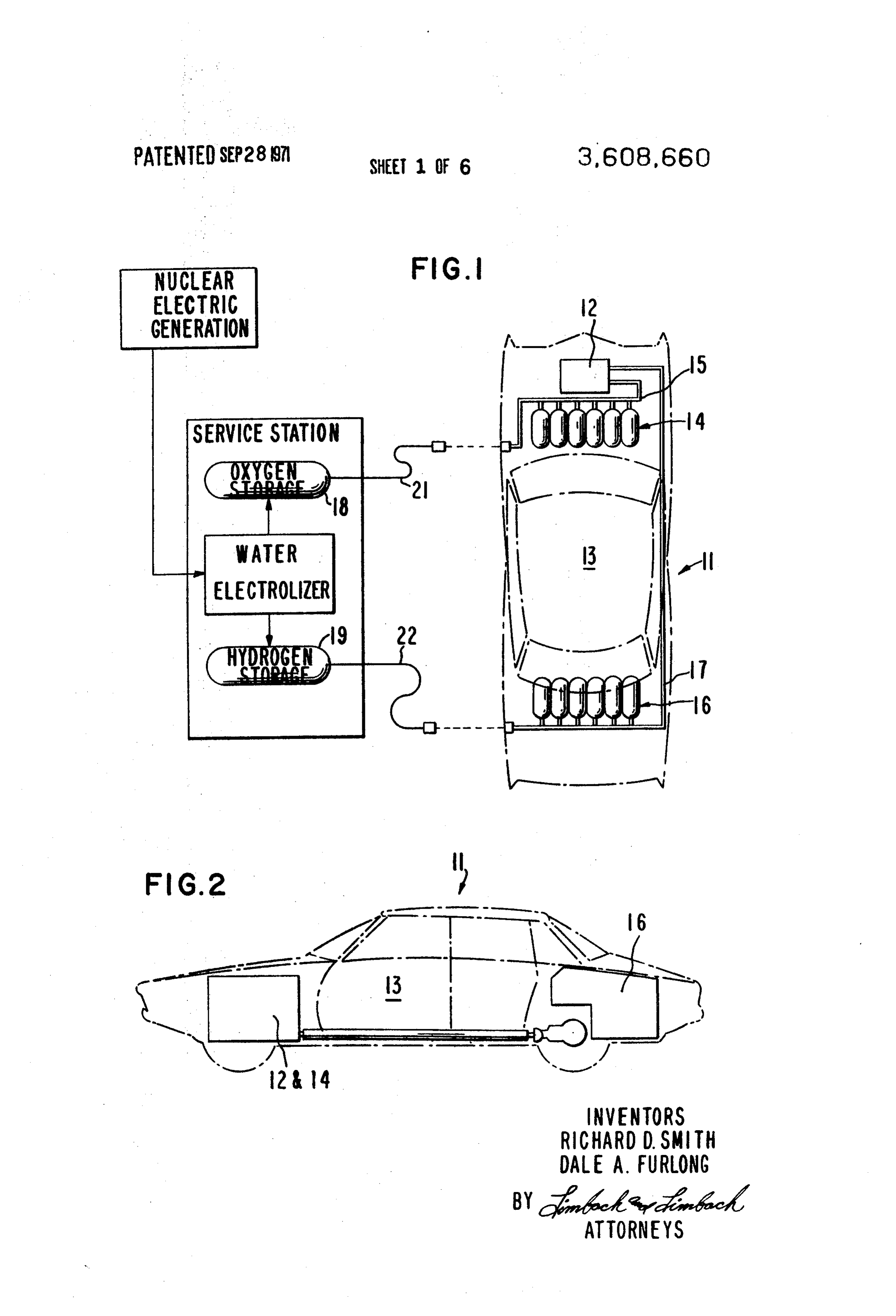
a smog-free two-stroke internal combustion engine is provided FIG. 2 is a schematic elevational view of the automobile ill utilizing Otto cycle operation for cruise power and Diesel lustrated in FIG. 1.
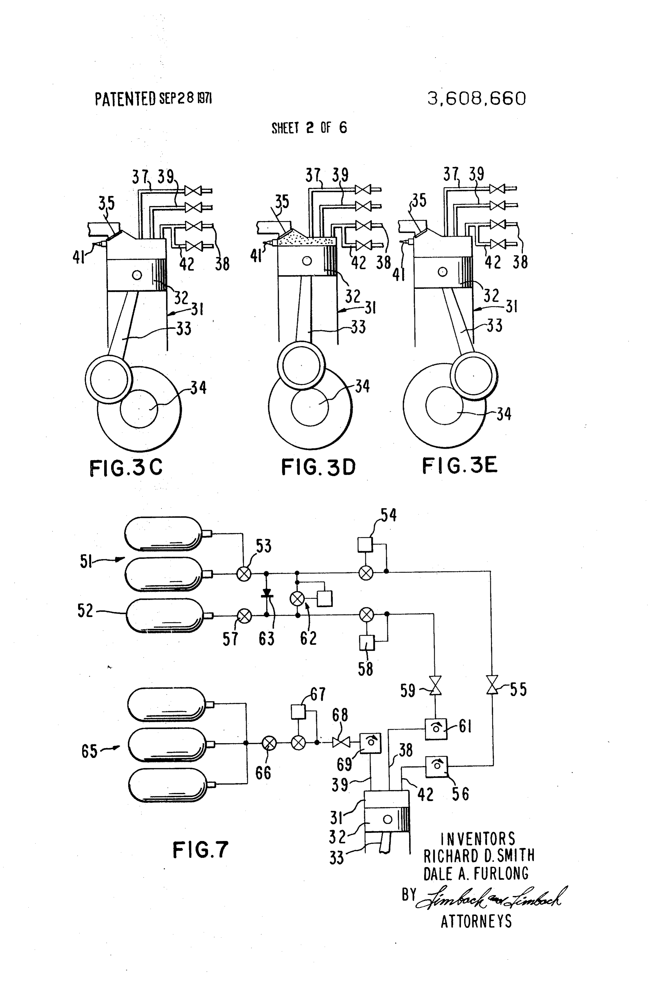
cycle operation for above-cruise power. With this construc FIGS. 3A-E are schematic elevational views of the engine tion and operation, an ideal engine is provided for a family 70 operation in accordance with this invention showing different sedan with maximum efficiency in the 25 to 50 horsepower piston positions.
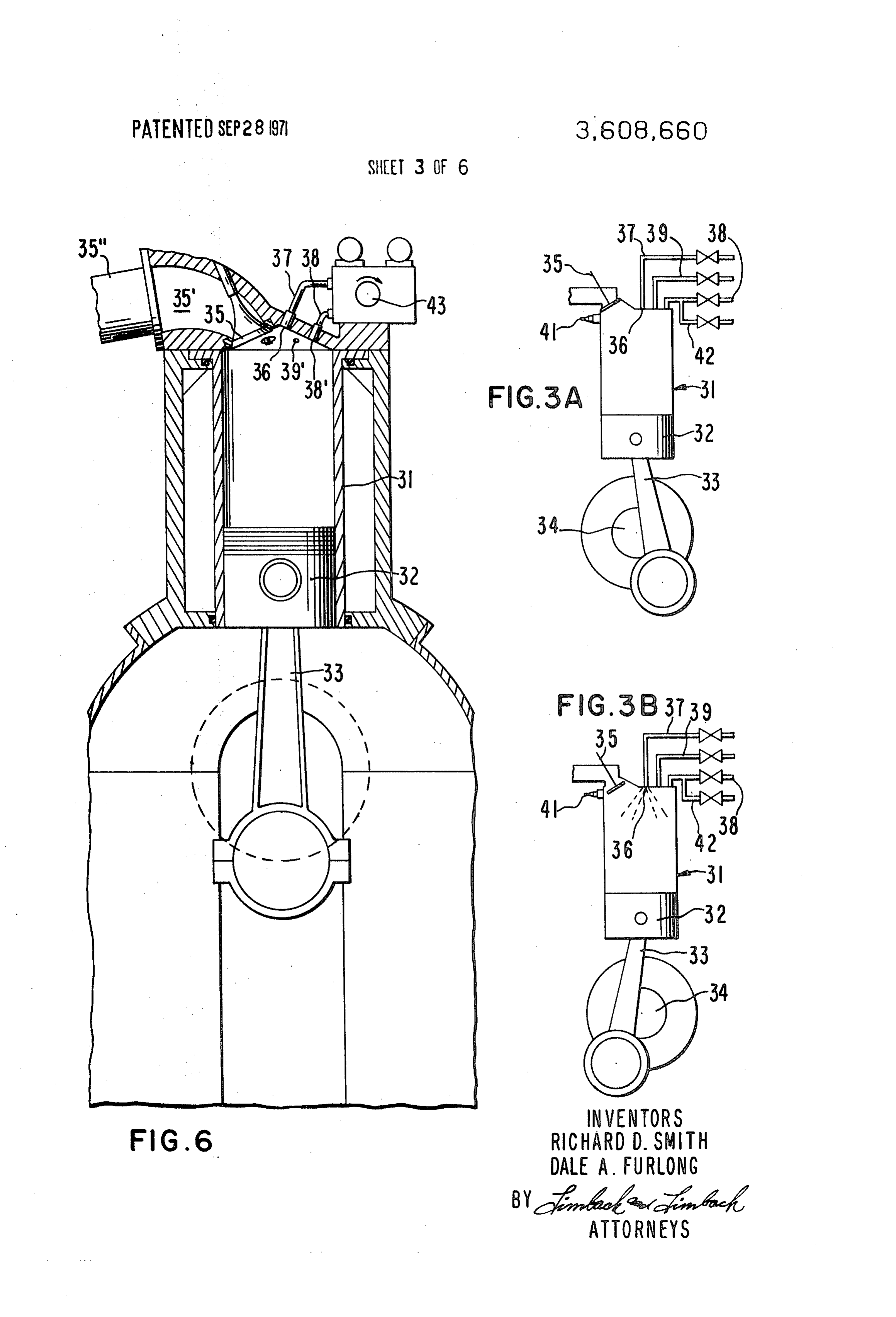
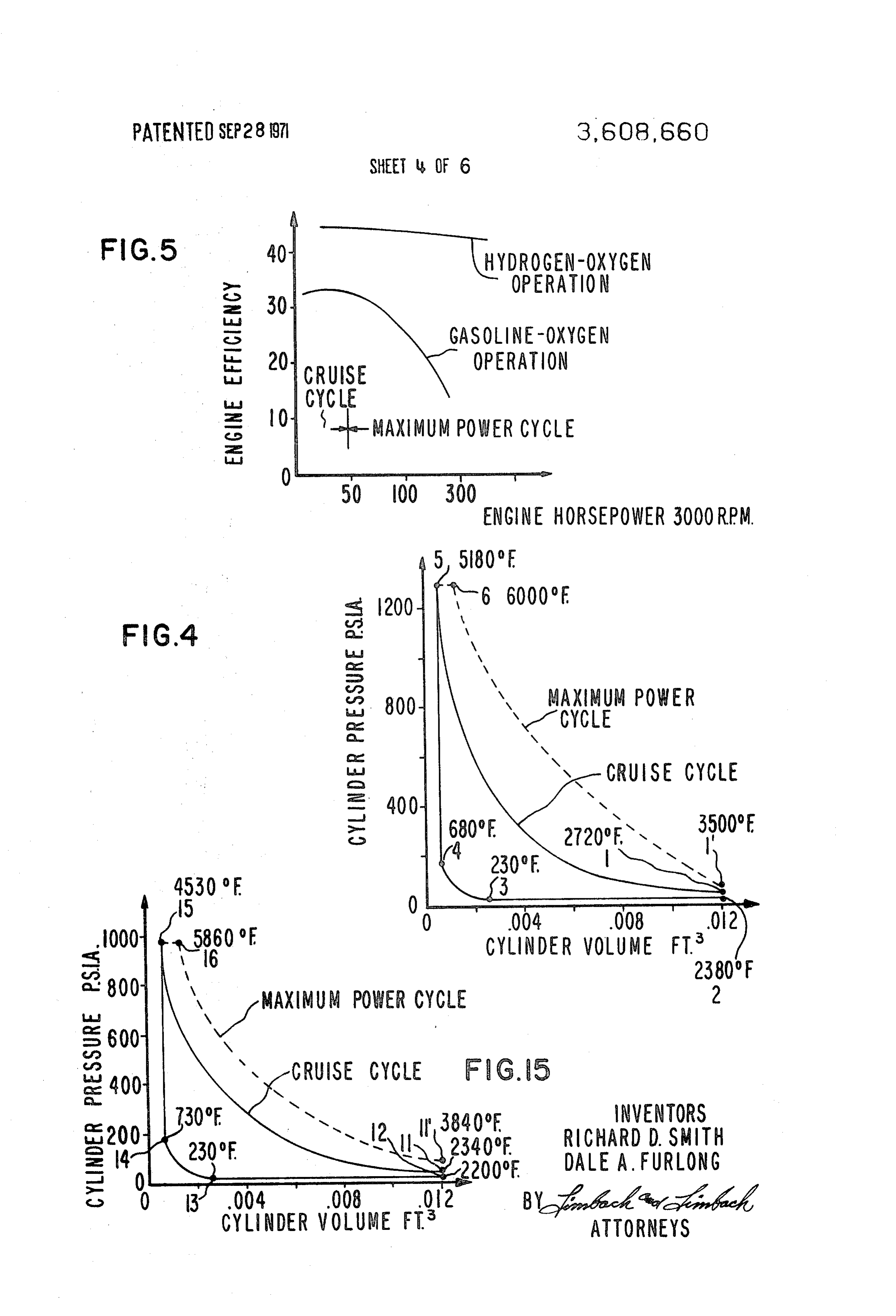
range yet capable of maximum powers of 200 horsepower and FIG. 4 is a graph of cylinder pressure vs. cylinder volume for a torque of 250 foot-pounds. one embodiment of the present invention. In accordance with still another aspect of the present inven FIG. 5 is a graph of engine efficiency vs. horsepowerfor two tion, water is recovered from the engine exhaust and recycled 75 embodiments of the present invention.
Page 9
FIG. 6 is an elevational sectional view of a portion of an en gine. The maximum power output of a conventional gasoline gine in accordance with the present invention. engine is directly proportional to the weight flow of air. FIG. 7 is a diagram schematically illustrating the fluid Therefor, at any given engine speed, power and torque are in supply system for an engine in accordance with the present in creased by increasing the displacement of the engine. Con vention.
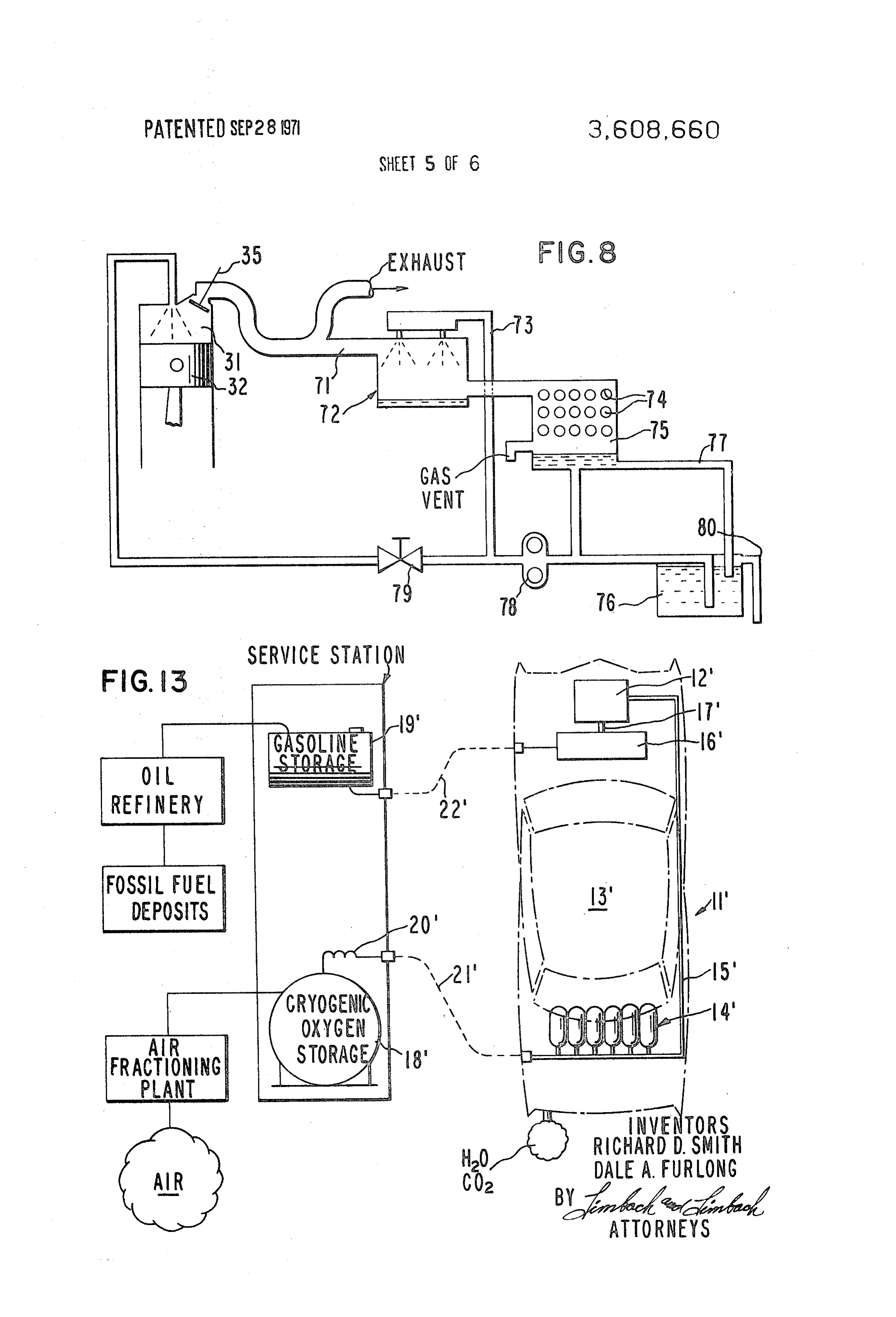
FIG. 8 is a drawing schematically illustrating the water spray sequently, conventional engines for family sedans tend to have and recovery system for this invention. rather large displacements; 300 cubic inches is considered FIG. 9 is a perspective view of a tankage assembly of this in normal today. When these engines are operated at 25 to 50 vention, horsepower which is a fraction of their maximum power, max FIG. 10 is a perspective view of one tank, partially broken O imum gas temperatures and pressure in the cylinders are reduced greatly because of heat transfer to the large surface away, utilized in this invention.
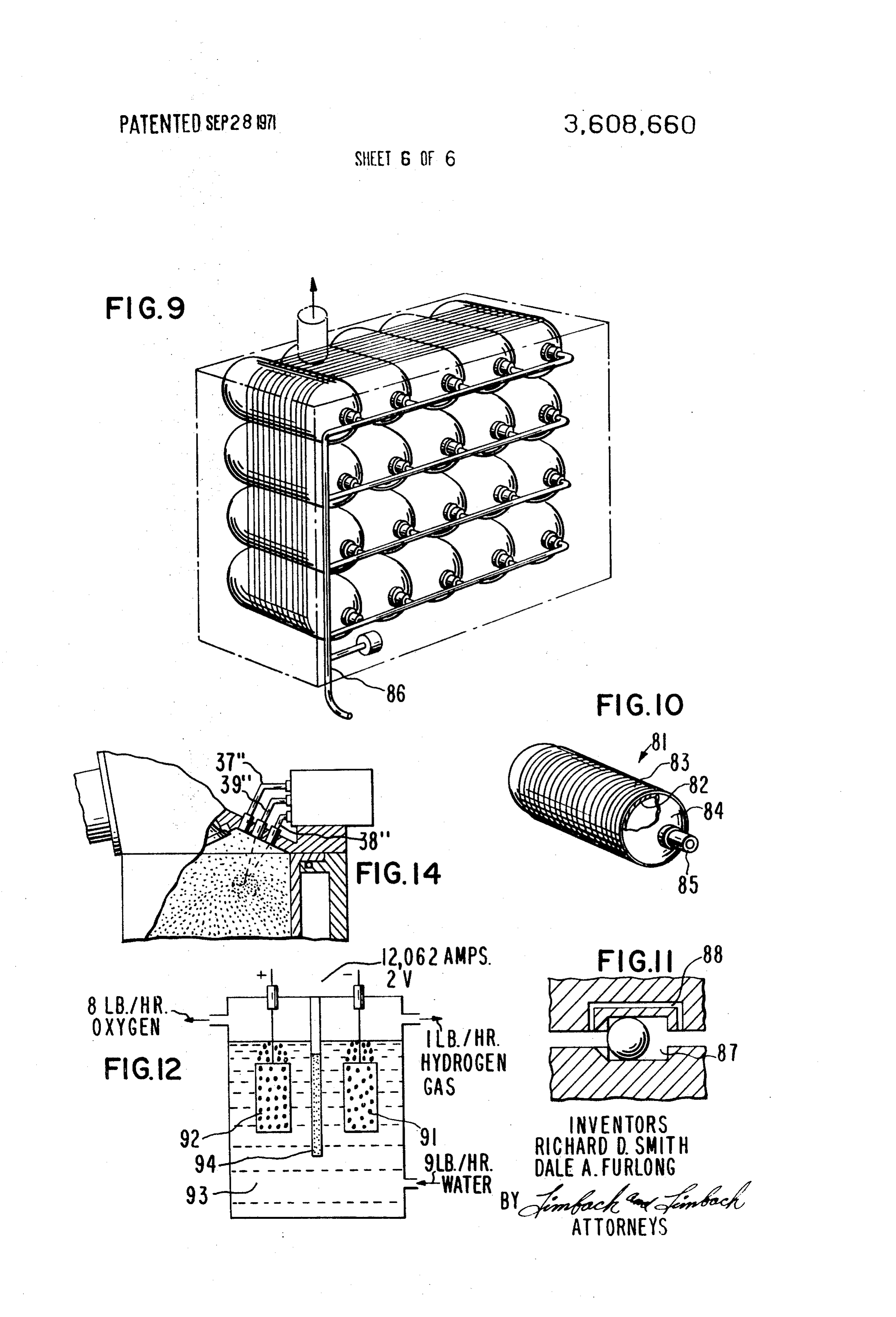
FIG. 11 is an enlarged sectional view of a tank valve used area within the combustion chamber thereby reducing ther mal efficiency. With the engine in accordance with the present for this invention.
FIG. 12 is an elevational view schematically illustrating an 15 invention, high efficiency is accomplished in the usual 25-50 horsepower cruising range, sacrificing efficiency in the seldom electrolysis apparatus in accordance with the present inven used, high-power range.
tion.
The engine in accordance with the present invention and its
FIG. 13 is a schematic view partially in block diagram form operation and partially in plan schematically illustrating certain aspects provided utilizingare unique in that an internal combustion engine is of the present invention. water vapor as the working fluid and em 20 ploying internal water spray cooling of the cylinder walls. The
FIG. 14 is an elevational sectional view of a portion of the operating cycle is a combination of the Otto cycle (constant engine structure in accordance with the embodiment of FIG. volume combustion) and the diesel cycle (constant pressure
FIG. 15 is a graph of cylinder pressure vs. cylinder volume powercombustion). The Otto portion of the engine cycle is used for for another embodiment of this invention. levels up to cruise power (40-50 horsepower); for max 25 imum performance, the constant pressure combustion is em
As set forth above, the present invention is directed to a smog-free internal combustion engine and method of operat ployed subsequent to the constant volume combustion. Refer ing same. It will be appreciated that this engine can be utilized ring now to FIGS. 3A-3B, there is illustrated the cruise cycle for many purposes. However, this engine is ideally suited for portion With of the engine in accordance with this invention.
particular reference to FIG. 3A, there is shown one of propelling a smog-free automobile and in combination with 30 the engine cylinders31 including a working member or piston other aspects of the present invention provides a smog-free 32 therein connected via a connecting rod 33 to a drive shaft system of vehicular travel. Therefore, the invention will be 34. The piston 32 is illustrated near the end of the power described in greater detail below as applied to a specific smog stroke after combustion of gaseous hydrogen and substantially free automobile and operational system. pure oxygen, The products of combustion and the working Referring now to the drawings with particular reference to 35 fluid (both superheated water vapor) have been expanded, FIGS. 1 and 2, a smog-free automobile 11 operating on com such as 20:1, and the exhaust valve 35 is about to open. bustion of gaseous hydrogen fuel and substantially pure ox The exhaust valve 35 opens just before bottom dead center ygen includes a two-stroke internal combustion engine 12 and the hot gas in the cylinder blows down to low pressure, the conveniently located in the front of the vehicle and provided gas in the cylinder expanding adiabatically. Shortly after the with substantially pure oxygen from a supply located adjacent 40 blowdown of the hot gas in the cylinder, water injection is in thereto and gaseous hydrogen from a supply located rear itiated through injector 36 at the closed end of the cylinder to wardly of the vehicle behind the passenger compartment 13.
The oxygen supply consists of a plurality of high-pressure cool 3B).
the cylinder walls, pistons, and exhaust valve (see FIG.
The exhaust valve 35 is left open until the piston has tanks 14 connected via a manifold 15 through pressure regula 45 changed the volume ratio, such as where only a 5:1 volume tors and throttle valves (not shown) to the engine 12. ratio remains, and then the exhaust valve 35 is closed (see Similarly, the hydrogen supply is contained in a plurality of FIG. 3C). During this exhaust portion of the stroke, the piston high pressure vessels 16 connected via a manifold 17 through 32 has scavenged the majority of the high temperature gas pressure regulating valves and throttle valves to the engine 12. (water vapor) from the cylinder. Some of the gas will be The automobile can be fueled at a service station with ox cooled directly by vaporizing the injected liquid as it flies
ygen and hydrogen from high pressure storage tanks 18 and toward the 19, respectively via quick disconnect, high pressure hoses 21 exhaust valve wall. The water hitting the walls, piston crown, and and 22, respectively. will flash into low-temperature steam, mixing with the residual high-temperature water vapor and cooling it
The oxygen and hydrogen in storage tanks 18 and 19 can be further. Some of this steam will pass out the exhaust valve generated at the service station in a unique high-pressure along with the residual hot gas. At the time the exhaust valve is water electrolyzer 23 which will produce gaseous hydrogen 55 closed, and gaseous oxygen at the desired pressure and in the propor is filled the volume remaining above the piston in the cylinder with saturated steam.
tions needed for combustion in engine 12. While the energy At the time of closing the exhaust valve 35, injection of for accomplishing water electrolysis can be provided by con gaseous oxygen and hydrogen from gas lines 38 and 39 respec ventional electric utility power generating stations, this energy 60 tively, is initiated. This injection occurs between closing of the can be provided by nuclear electric stations which are air pol exhaust valve and several degrees of crankshaft rotation be lution free or fossil-fueled plants designed to meet air pollu fore top dead center.
tion requirements. FIG. 3D shows ignition at top dead center where com in the embodiment of the invention illustrated and bustion begins and increases the pressure and temperature in described by illustrative example below, the engine 12 is less 65 the cylinder. Next, the hot gas (water vapor) is expanded 20:l than one-third of the size of an equivalent gas engine and to provide the work output. The hot gas transfers heat to the capable of being produced with convention internal com walls which is removed on the exhaust upstroke by spray cool bustion engine tooling. 1ng.
From studies on present day driving habits, the ideal engine To obtain maximum power, above the efficient cruise for the family sedan would provide maximum efficiency in the 70 power range, the engine operation described is augmented by horsepower range of about 25 to 50 horsepower yet be capa post ignition injection. FIGS. 3A-3D and FIG. 3E illustrative ble of a maximum power of 200 horsepower and torque of 250 the various steps of this cycle. In this cycle, at the end of the lb.-feet. Such a family car requires an energy storage of about power 134 horsepower hours delivered to the wheels. These require hot gasstroke (FIG. 3A) before the exhaust valve opens, the in the cylinder is at a temperature and at a pressure ments are difficult to meet with a conventional gasoline en- 75 above that at the end of the cruise cycle power stroke. After
Page 10
the exhaust valve opens and the cylinder blows down, the hot During compression and fuel and oxygen injection, only gas in the cylinder expands adiabatically. that part of the oxygen is injected to reach a maximum Water spray is initiated (FIG.3B) at bottom dead center, as cylinder pressure of 1300 p.s.i.a. This results in an oxygen to it was for the cruise cycle. The pressure of the water spray is fuel ratio of 2.6, well within the combustion limits. The overall increased to increase the flow rate because additional water oxygen to fuel ratio for hydrogen-oxygen combustion is will be required for cooling. After the closing of the exhaust O/F=8, the stoichiometric ratio. valve 35 (FIG. 3C) and during the compression stroke, all of After ignition the fuel rich hydrogen and oxygen mixture the hydrogen fuel is injected but only that portion of the ox burns to produce hot gas at 1300°F. and additional high-pres ygen is injected which is required for the reaction to reach a sure oxygen is injected to burn fuel at 1300 p.s. i.a. until all the maximum cylinder pressure. O hydrogen has burned and the hot gas reaches about 6000 F.
The conditions in the cylinder at the end of compression are (point 6 in FIG. 4) similar to those of the cruise cycle, except that pressure is At the start of the expansion stroke, the expansion ratio has slightly greater due to the pressure of the additional hydrogen. been reduced from 20:1 to 8.15:1 by the previous constant Ignition occurs at top dead center by means of a spark ignition pressure expansion shown at point 6 on the diagram of FIG. 4 from spark plug 41 and the fuel rich mixture burns to produce 15 for the maximum power cycle in addition to that of the cruise hot gas. Concurrently, (FIG.3E) a valve in a high-pressure ox cycle. The engine as described produces 216 horsepower at ygen line 42 is opened to supply additional oxygen to burn the 3000 r.p.m. when operating at conditions as discussed for the remaining fuel at a constant pressure. maximum power cycle.
Since hydrogen has a spontaneous ignition temperature in FIG. 5 illustrates the curve of the engine efficiency as a air of 1085 F., hydrogen will exhibit characteristics for an en function of engine horsepower at a constant speed of 3000 gine "knock' standpoint similar to high-grade gasoline. Under r.p.m. The curve peaks at an efficiency of 45 percent at 60 circumstances where knock does occur and detonation horsepower (slightly more than required for normal driving) becomes unavoidable, the hydrogen is injected on the up but drops off very little at the higher horsepower levels, with stroke as described above, but the oxygen injection is initiated 25 the maximum power cycle. One would normally expect a shortly before top dead center and the hydrogen is progres sharper drop off at the higher powers because the expansion sively burned as the oxygen is admitted. ratio is greatly reduced due to the constant pressure portion of For a clear understanding of the present invention, the the cycle (post ignition injection). This trend toward lower ef. parameters of an illustration embodiment will be given and ficiencies is off set by the increasing temperature of the hot operating characteristics are shown in the pressure versus 30 gas in the cylinder, tending toward increasing the efficiency. volume graph of FIG. 4. As shown at the end of the expansion High efficiency of this engine is due in large part to the excel stroke of the cruise cycle (FIG. 3A), the cylinder pressure is lent thermodynamic properties of water vapor as compared 39 p.s.i.a. and the water vapor temperature is 2720 F. at point with carbon dioxide or air. The work obtained from a given 1 in FIG. 4. When the exhaust valve opens the gas expands weight of gas is inversely proportional to the molecular weight adiabatically from 39 p.s.i.a. to 20 p.s.i.a. reducing the gas 35 of the gas and while carbon dioxide and air have molecular temperature to 2380° F. at point 2 in FIG. 4. At these tem weights of 44 and 29, respectively, the molecular weight of peratures, the speed of sound in water vapor is approximately water vapor is 18.
3,000 ft/sec. and it takes approximately 1/10 milliseconds for A simplified side elevational sectional view of the smog-free the pressure waves to reach the piston (or 3 of crankshaft engine is illustrated in FIG. 6. For the illustrative embodiment rotation at 5,000 rp.m.) before the flow starts out of the 40 as described above, the two-stroke engine has four in-line cylinder after the valve has first opened. cylinders each with a bore of 2.6 inches and a stroke of 4 For providing the water spray during the exhaust stroke of inches. The exhaust is removed from the cylinder 31 through a the cycle the injector 36 at a port in the closed end of the en single overhead valve 35 via exhaust port 35' and exhaust gine cylinder can have a pressure differential of 120 p.s.i.a. 45 manifold 35' with valve 35 operated by an overhead cam (not from a water line 37 causing the water spray to attain a shown) driven by a toothed rubber belt. With an expansion velocity of approximately 100 ft/sec. Consequently, approxi ratio of 20:1, the volume of each combustion chamber is l.04 mately 2 milliseconds is required for a droplet to reach a point cubic inches. The engine 12 uses the crankshaft from a con on the cylinder wall 3 inches from the top of the combustion ventional v-8 engine (4 inch stroke). The water spray injector chamber. At 5,000 rp.m. this travel requires about 60° of 36, the oxygen and hydrogen inlet port 38' and 39' and the crankshaft travel and if the water spray is initiated at bottom 50 sparkplugs 41 are all located in the head 42. The water injec dead center, the droplet will reach the wall at the above tor spray36 is centered in the bore to provide a uniform spray referred to location shortly before the piston coversit. to the cylinder walls. Water, hydrogen, and oxygen are me At the time when the exhaust valve 35 closes (point 3 in tered by valves driven by an auxiliary cam such as shaft 43 in FIG. 4), substantially only saturated steam at about 230 F. 55 turn driven by a toothed belt (not shown). The hydrogen me remains above the piston and compression begins. tering valves are separated from the oxygen and water meter The maximum pressure in the cylinder rises only to 165 ing valves to provide complete separation of the materials p.s.i.a., consequently the back pressure against the gas during until injection into the combustion chamber. A typical engine injection is minimal. Adiabatic compression of the steam at constructed in accordance with the present invention is 27 230 F. (Over a 5:1 compression ratio) plus the introduction 60 inches long, 25 inches high, 15 inches wide, and weighs ap of hydrogen and oxygen results in a cylinder pressure of 165 proximately 220 pounds.
p.s.i.a., and a gas temperature of 680°F, as shown at point 4 in The hydrogen and oxygen injected prior to ignition for the FIG. 4. After ignition the cylinder pressure increased to about cruise portion of the cycle are injected over a crankshaft 1300 p.s.i.a. and the temperature of the gas therein to about travel of about 45 for 1.5 milliseconds at 5000 rp.m. The 5180° F. (point 5 in FIG. 4). Then with expansion during the 65 dwell angle of injection remains constant, and the amount of working stroke the pressure and temperature return to that at hydrogen and oxygen to be injected is determined by throt point 1 in FIG. 4. tling upstream of the valve.
In the maximum power or Diesel cycle operation the power The oxygen injected after top dead center for maximum stroke ends with a hot gas at a pressure of 71.5 p.s.i.a. and a power is injected over a fixed dwell and of about 30' of temperature of about 3500 F. (point 1 in FIG. 4). Upon 70 crankshaft travel for 1 millisecond at 5000 rp.m. With a back opening of the exhaust valve the hot gas in the cylinder ex pressure of 1300 p.s.i.a., 300 p.s.i.a. pressure drop is provided pands adiabatically to a pressure of 20 p.s.i.a. and a tempera through the valve. The oxygen is throttled upstream of the in ture of 2760° F., and after the water spray and exhaust satu jection valve to provide throttling for maximum power and rated steam remains at 230 F. and 20 p.s.i.a., the same condi concurrent throttling of the hydrogen injected prior to dead tions exist for the cruise cycle (point 3 in FIG. 4). center is also injected.
Page 11
FIG. 7 is a schematic view of the gas injection system for the returned to a reservoir 76 via a line 77. A pump 78 circulates engine described above. Both oxygen and hydrogen are stored water from the reservoir 76 to line 73 directed to the desuper initially such as at 5000 p.s.i.a. in high-pressure cylinders. The heater and through a throttle valve 79 to the spray head 36 for gas injection system of the illustrative embodiment utilizes the the spray during the exhaust cycle. The reservoir 76 accom lowest possible gas injection pressure, 500 p.s.i.a. to take max modates time when maximum power is required and during imum advantage of the capacity of the storage tanks. If the which slightly more water is used in operation than recovered. pressure drops below the gas injection pressure, the engine begins to lose power, thereby warning the driver to stop at a This lost water is recovered during cruise conditions and once the reservoir 76 is full, excess recovered water is allowed to service station and fill up. A special high pressure oxygen exhaust via an overflow pipe 80. system is used for post ignition for the maximum power cycle. O
In freezing
As illustrated, the oxygen storage tanks are segregated into the reservoir allowing climates a small hole is provided in the bottom of two groups, cruise oxygen tanks 51 and maximum power ox operation is complete.theSimilarly, water to leak out of the system when the high-pressure line is ygen tanks 52. Typically, the cruise oxygen tanks are on the vented at shut down to allow it also to drain. While no water is order of 90 percent of the tool supply. Cruise oxygen from tanks 51 goes through a shutoff valve 53 actuated by the igni 15 available in these for cooling at start up of the engine, none is needed freezing climates. The engine walls are chilled and the tion key and a pressure reducing regulator 54 to reduce the oxygen pressure to the approximately 500 p.s.i.a. referred to desuperheater and condenser are cold. Condensation col lected in the system at start up will provide sufficient water to above. At the engine 12 oxygen passes through a throttling start the system into operation.
valve 55 controlled by the automobile accelerator (not 20 The assembly and construction of gaseous pressure tanks shown) and the injection valve 56 to inject oxygen into the for storage of high pressure hydrogen and oxygen is illustrated cylinder at the proper time of the cycle. in FIG. 9-11. As shown, each of the tanks 81 is formed of a The oxygen from tanks 52 to provide maximum power goes composite structure having a liner 82 formed of a thin gauged through a shutoff valve 57 and a pressure reducing regulator steel overwound 58 to a pressure, such a 1600 p.s.i.a., above the constant pres 25 83. The ends ofwith a wrap of tensioned glass filament fibers the liner 82 are closed with hemispherical sure level of the power cycle, and then through a throttle valve members 59 and injection valve 61. To insure complete utilization of all Cylindrical84vessels and provided with a neck opening 85 in one end. as the liner 82 essentially have tension oxygen, a valving assembly is provided for connecting the con stresses in two directions:
duits of the cruise oxygen and power oxygen tanks 51 and 52, load, and those caused by thethose caused by the longitudinal circumferential load, referred to respectively, when either the pressure in the cruise oxygen 30 as hoop stresses. These hoop stresses are approximately twice tank line falls to 500 p.s.i.a. or the pressure in the power ox as large as the longitudinal stresses. Since glass fiber filaments ygen tank line falls to 1600 p.s.i.a. This valving assembly can have several times the strength to weight ratio of steel, tanks include a regulator 62 which allows oxygen from tank 52 to 81 of composite structures for the high-pressure system in ac bleed into the cruise tank line to maintain a pressure of 600 cordance with the present invention allow the placing of the p.s.i.a. and a check valve allowing cruise tank oxygen to bleed 35 high strength fibers in the direction of the load. This results in into the maximum power oxygen line if the maximum power dramatically reduced weight and increased safety factors for oxygen pressure drops below the cruise tank pressure.
The hydrogen system is similar to the cruise oxygen system to accident, the fiberglassalining the smog-free car. Should composite vessel be fractured due wall in all probability retain including pressure tank 65, a shutoff valve 66, a pressure the integrity of the pressure vessel while gas escapes. reducing valve 67, a throttle valve 68 and an injection valve 69 40
For maximum safety consistent with reasonable cost and except throttle valve 68 is arranged to introduce additional size, the hydrogen and oxygen high-pressure tank storage as hydrogen into the cylinder during the maximum power cycle. sembly utilizes clusters of small composite tanks 81 as shown The water injection spray head 36 is designed to provide a in FIG. 9. The tanks each are lined with a material to protect medium fine spray into the cylinder 31. If the spray is too fine, it will be evaporated in the gas and not reach the cylinder 45 steel from rusting or corrosion and the tank overwrapped with fiberglass tension windings to hold the cluster together in the walls; if the spray is too coarse, it will not be distributed presence of pressure forces that would be thrust on adjacent uniformly on the cylinder walls. Consequently, only nominal bottles during a period when gas is escaping.
pressures, such as 120 p.s.i.a., are needed for the water spray In the typical illustrative example given on the present in nozzle.
In the particular illustrative embodiment given herewith, 50 vention, tanks 20 inches long and 5.5 inches diameter holding approximately 0.00015 pounds of water are required to cool 35Based cubic inches of gas at 5000 p.s.i.a. are utilized. upon the energy storage requirements of 134 hor the cylinder after each power stroke. Under maximum power sepower hours discussed above and the hydrogen/oxygen en this figure increases to 0.0004 pounds per stroke. While these gine average efficiency of 44 percent for normal driving, the figures appear insignificant, 86 pounds of water would be 55 gas storage and tankage requirements for the engine are 17 required for a 1 hour cruising. Consequently, a system is em pounds of hydrogen and 153 pounds of oxygen. This amount ployed to condense a portion of the exhaust to supply distilled of hydrogen can be stored in 61 of the tanks described and the water for the injection system. oxygen in 34 of these tanks.
FIG. 8 presents a schematic diagram of the cooling water For safety sake, the hydrogen tankage and oxygen tankage system of this invention. For the illustrative example given 60 are widely separated to preclude an accidental mixing of the here the cooling system is sized to operate continuously for gases due either to leakage or in the event of a severe collision. maximum cruise power. On each stroke, 0.00015 pounds of The water are injected into cylinder 35 for cooling 0.00032 truckhydrogen tanks are mounted in the forward part of the with a steel fire wall aft of the back seat to isolate the pounds of steam at 2060° F. at atmospheric pressure are ex hydrogen tank storage from the passenger compartment. In hausted from the cylinder 31, the combustion of hydrogen and 65 oxygen contributing to the water vapor. If less than 50 percent this location, the hydrogen tanks are the least likely to be penetrated in the event of a violent crash. If penetrated, the of the exhaust is directed to the atmosphere and the remainder hydrogen gas escapes rearward and upward and if a fire directed via a line 71 to a desuperheater 72, sufficient water results, it is directed away from the passengers. Present cars can be recovered for continuous operation of the engine with mount their gasoline tanks in the rear for similar reason, and the water spray utilized during the exhaust stroke. In the desu 70 fires perheater 72, water from a return line 73 is sprayed into the even due to spilled gasoline are rare with injuries due to fire more rare. The 61 tanks can be fitted into the truck area superheated stream, and the evaporation of this water cools the superheated stream to near saturation conditions. Utilizing of existing cars and the 34 oxygen tanks mounted under the hood adjacent the engine.
water from the automobile radiator in circulation tube 74 of a Because of the tank weight and oxygen weight, this automo condenser 15, the saturated steam can be condensed and 75 bile is heavier than a comparable gasoline engine car. Reduc
Page 12
tion in the size of the engine compensates in part for the added oxygen, are burned to provide maximum efficiency in the tank weight of hydrogen and oxygen. The weight for an 25-50 horsepower range capable of maximum power of 200 average conventional gasoline engine family car is approxi mately 3500 pounds with a weight distribution of 55 per parison, theand horsepower 250 lbs.-ft. of torque. For purposes of com centl45 percent between the front and back, respectively. The present invention is indesigned engine accordance with this aspect of the with the same displacement, weight of the automobile in accordance with the present in bore, stroke as the smog-free engine utilizing hydrogen and vention would be about 3925 pounds with a weight distribu oxygen described above. The automobile burning gasoline and tion of 45 percent/53 percent between front and back. The oxygen operates basically on the same cycle added weight on the back wheels adds traction in slippery and oxygen burning automobile but derives itsas pollution-free the hydrogen weather and reduces wheel spin for heavier automobiles. 10
To prevent the hydrogen from all other tanks from going gasoline potential from completely oxidizing the hydrocarbons in through the manifold 86 and escaping through a ruptured mixtures incanabsence of nitrogen. Consequently, oxygen rich be used to thoroughly oxidize the fuel without tank, each tank is equipped with a hydraulic fuse. The hydrau the usual production of nitrogen oxides. lic fuse is in the form of a normally open check valve that per 15 The gasoline and oxygen burning automobile system is illus mits rapid tank filling but only a limited flow rate leaving the trated in FIG. 13 wherein the internal combustion engine 12' tank such as would be experienced in normal use. If a failure as described above and modified in accordance with the occurs and rapid flow is initiated, the flow entrains a simple description below for burning gasoline and oxygen is located ball which closes the check valve and stops the flow. A small in front of the vehicle 11" along with the gasoline supply 16'. bleed line 88 bypassing the check valve is installed to allow the 20 The tank to slowly reduce in pressure, such as over the period of an shownoxygen supply in a tankage assembly 14' such as that in FIG. 9 is located at the rear of the automobile and hour or two, thereby decompressing the tanks to remove connected to the engine 12' through a manifold 15'. It will be hazard in later disassembly or repair.
The engine described in the illustrative example thus far appreciated that the location of the gasoline supply 16' and provides 360 horsepower under the hood and a torque of 380 the oxygen supply 14' can be reversed so long as they are lbs.-ft. thereby ranking with the best on the market today. Ac separated from one another for safety in case of a collision.
The automobile celeration times of 0 to 60 m.p.h. in 7.8 seconds should be storage 19' for gasoline is serviced at a service station having a realizable along with a top speed of 125 m.p.h. Driving in a and a cryogenic storage 18" obtained from conventional sources for oxygen such as obtained from conventional style, the automobile has a range of 200 miles in the air by means of an air fractioning plant. Liquid oxygen in city driving and 350 miles on freeway at a steady 70 m.p.h. 30 storage 18' is converted to high pressure gaseous oxygen in Gaseous hydrogen and oxygen are available from industrial converter 20' for delivery to the automobile via hoses with sources of supply in large quantities. Considering the quick disconnect fitting.
widespread use of hydrogen and oxygen that would result The operation of the engine in accordance with this em from the general introduction of an automobile of this con bodiment of the present invention conforms generally to the struction, the generation of hydrogen and oxygen directly by 35 operation described above with reference to FIGS. 3A-3E but use of electric current in each service station has several ad wherein liquid gasoline instead of gaseous hydrogen is vantages over expanding commercial sources of supply. The directed into the cylinder through line 39. The gasoline is main advantage would be a completely pollution-free system. burned in a gas mixture with a high oxygen concentration and In accordance with another aspect of the present invention, typically with 15 percent excess oxygen. As a result, at the end nuclear electrical generating stations providing electricity for 40 of he combustion the electrolysis of water to produce the desired amount of bons of the gasolinestroke are as shown in FIG. 3A, the hydrocar completely oxidized to water and car hydrogen and oxygen for the smog-free car provides such a bon dioxide. The same dual Otto cycle and Diesel cycle as pollution-free system. described above is utilized for cruise powers and maximum In accordance with still another aspect of the present inven powers above cruise level.
tion, the electrolysis water is utilized to generate the oxygen 45 and hydrogen for the smog-free automobile. Pure oxygen and ranged As illustrated in FIG. 14, the gas fuel inlet port 39' is ar with respect to he gaseous oxygen inlet port 38' such hydrogen are produced in the precise ratio required for com that within the cylinder 31' the jet of oxygen from inlet port bustion such that water only is formed. FIG. 12 shows the basic components and the quantity relationships of a water 50 38' hits the stream of liquid gasoline entering through port 39'whereby the gasoline is finely atomized and dispersed electrolyzer. When an electric current flows, bubbles of throughout the combustion chamber within the cylinder. The hydrogen gas form on the cathode plate 91 while bubbles of gasoline and oxygen are not mixed prior to introduction into oxygen gas from at anode 92. A 15 percent to 30 percent solu the cylinder for reasons of safety. tion of potassium hydroxide is used as the electrolyte 93. A The graph showing cylinder pressure vs. cylinder volume for woven asbestos diaphragm is placed between the electrodes the engine burning liquid gasoline and gaseous oxygen is illus 91 and 92 to prevent mixing of the gas bubbles but to permit 55 trated in FIG. 15 and wherein points 11-16 corresponds passage of the electrolyte. At the cathode, hydrogen ions respectively with points 1-6 described above with reference to receive electrons forming hydrogen gas. Hydroxyl ions are at FIG. 4 in setting forth the operation of the engine burning tracted to the anode, give up an electron, and form oxygen gas hydrogen and oxygen.
plus water. The potassium hydroxide is not consumed but is 60 necessary to generate the necessary ions to permit the electric areIn burned this embodiment of the invention, the hydrocarbon fuels substantially completely to eliminate carbon current flow. monoxide and unburned hydrocarbon. The presence of in a service station as shown in FIG. 1, the storage tanks nitrogen oxide is not possible since no nitrogen is present in need only be adequate to handle peak rates and to minimize the cylinder. When fuels are burned in highly concentrated use of electric power during peak power periods since gases 65 oxygen environments, intimate contact between fuel can be continuously generated. A storage capacity of 200 molecules and the oxygen molecules is possible. Compared to cubic feet of hydrogen and 100 cubic feet of oxygen is the combustion of the same fuel in air, the burning rate is in adequate to fuel 25 smog-free cars of the type described creased; the temperature of the products of combustion is above. The cost of this fuel per mile utilizing the smog-free car higher; and the thoroughness of combustion of the fuel is and this hydrolysis generation of hydrogen and oxygen is ap 70 much easier to obtain.
proximately the cost per mile for a conventional gasoline en Since air contains about 78 percent nitrogen and 21 percent gine. oxygen by volume, and 75.8 percent nitrogen 23.2 percent ox In accordance with still another aspect of the present inven ygen by weight, the diluting effect of nitrogen can well be ap tion, a smog-free car and method of operating the same is pro preciated. Nitrogen does not contribute to the oxidation vided wherein gasoline and oxygen, rather than hydrogen and 75 process but acts to dilute the effective oxygen concentration,
Page 13
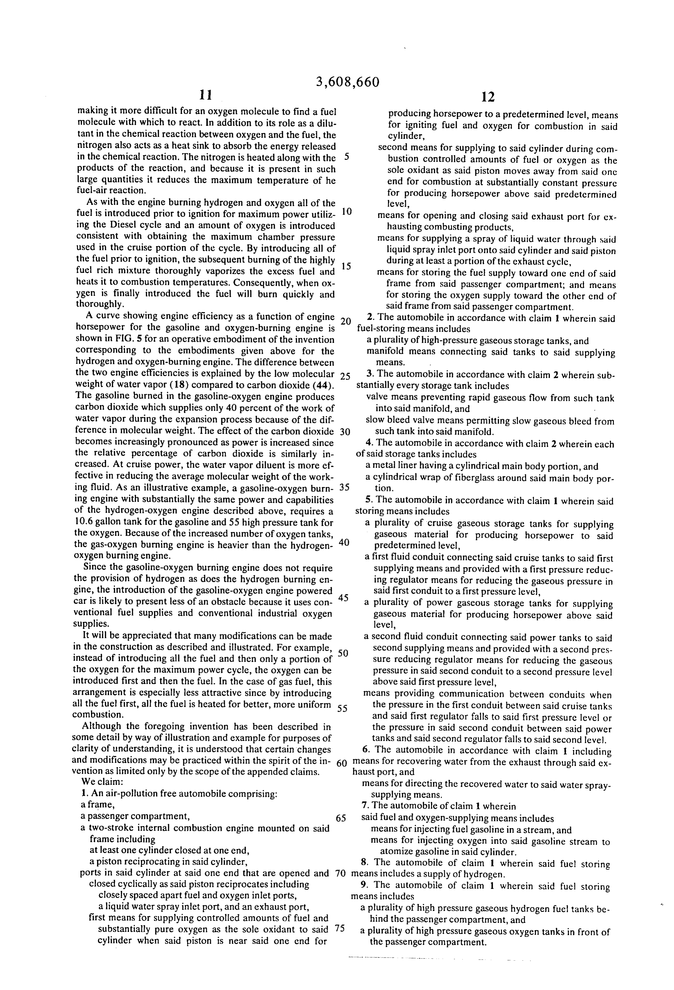
making it more difficult for an oxygen molecule to find a fuel producing horsepower to a predetermined level, means molecule with which to react. In addition to its role as a dilu for igniting fuel and oxygen for combustion in said tant in the chemical reaction between oxygen and the fuel, the cylinder, nitrogen also acts as a heat sink to absorb the energy released second means for supplying to said cylinder during com in the chemical reaction. The nitrogen is heated along with the 5 bustion controlled amounts of fuel or oxygen as the products of the reaction, and because it is present in such sole oxidant as said piston moves away from said one large quantities it reduces the maximum temperature of he end for combustion at substantially constant pressure fuel-air reaction. for producing horsepower above said predetermined As with the engine burning hydrogen and oxygen all of the level, fuel is introduced prior to ignition for maximum power utiliz 10 means for opening and closing said exhaust port for ex ing the Diesel cycle and an amount of oxygen is introduced hausting combusting products, consistent with obtaining the maximum chamber pressure means for supplying a spray of liquid water through said used in the cruise portion of the cycle. By introducing all of liquid spray inlet port onto said cylinder and said piston the fuel prior to ignition, the subsequent burning of the highly 15 during at least a portion of the exhaust cycle, fuel rich mixture thoroughly vaporizes the excess fuel and means for storing the fuel supply toward one end of said heats it to combustion temperatures. Consequently, when ox frame from said passenger compartment; and means ygen is finally introduced the fuel will burn quickly and for storing the oxygen supply toward the other cnd of thoroughly. said frame from said passenger compartment. A curve showing engine efficiency as a function of engine 2. The automobile in accordance with claim 1 wherein said horsepower for the gasoline and oxygen-burning engine is 20 fuel-storing means includes shown in FIG. 5 for an operative embodiment of the invention a plurality of high-pressure gaseous storage tanks, and corresponding to the embodiments given above for the manifold means connecting said tanks to said supplying hydrogen and oxygen-burning engine. The difference between aS.
the two engine efficiencies is explained by the low molecular 25 3. The automobile in accordance with claim 2 wherein sub weight of water vapor (18) compared to carbon dioxide (44). stantially every storage tank includes The gasoline burned in the gasoline-oxygen engine produces valve means preventing rapid gaseous flow from such tank carbon dioxide which supplies only 40 percent of the work of into said manifold, and water vapor during the expansion process because of the dif slow bleed valve means permitting slow gaseous bleed from ference in molecular weight. The effect of the carbon dioxide 30 such tank into said manifold. becomes increasingly pronounced as power is increased since 4. The automobile in accordance with claim 2 wherein each the relative percentage of carbon dioxide is similarly in of said storage tanks includes creased. At cruise power, the water vapor diluent is more ef a metal liner having a cylindrical main body portion, and fective in reducing the average molecular weight of the work a cylindrical wrap of fiberglass around said main body por ing fluid. As an illustrative example, a gasoline-oxygen burn 35 tion.
ing engine with substantially the same power and capabilities 5. The automobile in accordance with claim 1 wherein said of the hydrogen-oxygen engine described above, requires a storing means includes 10.6 gallon tank for the gasoline and 55 high pressure tank for a plurality of cruise gaseous storage tanks for supplying the oxygen. Because of the increased number of oxygen tanks, 40 gaseous material for producing horsepower to said the gas-oxygen burning engine is heavier than the hydrogen predetermined level, oxygen burning engine. a first fluid conduit connecting said cruise tanks to said first Since the gasoline-oxygen burning engine does not require supplying means and provided with a first pressure reduc the provision of hydrogen as does the hydrogen burning en ing regulator means for reducing the gaseous pressure in gine, the introduction of the gasoline-oxygen engine powered 45 said first conduit to a first pressure level, car is likely to present less of an obstacle because it uses con a plurality of power gaseous storage tanks for supplying ventional fuel supplies and conventional industrial oxygen gaseous material for producing horsepower above said supplies. level,
It will be appreciated that many modifications can be made a second fluid conduit connecting said power tanks to said in the construction as described and illustrated. For example, 50 second supplying means and provided with a second pres instead of introducing all the fuel and then only a portion of sure reducing regulator means for reducing the gaseous the oxygen for the maximum power cycle, the oxygen can be pressure in said second conduit to a second pressure level introduced first and then the fuel. In the case of gas fuel, this above said first pressure level, arrangement is especially less attractive since by introducing means providing communication between conduits when all the fuel first, all the fuel is heated for better, more uniform 55 the pressure in the first conduit between said cruise tanks combustion. and said first regulator falls to said first pressure level or Although the foregoing invention has been described in the pressure in said second conduit between said power some detail by way of illustration and example for purposes of tanks and said second regulator falls to said second level. clarity of understanding, it is understood that certain changes 6. The automobile in accordance with claim 1 including and modifications may be practiced within the spirit of the in 60 means for recovering water from the exhaust through said ex vention as limited only by the scope of the appended claims. haust port, and
We claim: means for directing the recovered water to said water spray 1. An air-pollution free automobile comprising: supplying means.
a frame, 7. The automobile of claim 1 wherein a passenger compartment, 65 said fuel and oxygen-supplying means includes a two-stroke internal combustion engine mounted on said means for injecting fuel gasoline in a stream, and frame including means for injecting oxygen into said gasoline stream to at least one cylinder closed at one end, atomize gasoline in said cylinder. a piston reciprocating in said cylinder, 8. The automobile of claim 1 wherein said fuel storing ports in said cylinder at said one end that are opened and 70 means includes a supply of hydrogen.
closed cyclically as said piston reciprocates including 9. The automobile of claim 1 wherein said fuel storing closely spaced apart fuel and oxygen inlet ports, means includes a liquid water spray inlet port, and an exhaust port, a plurality of high pressure gaseous hydrogen fuel tanks be first means for supplying controlled amounts of fuel and hind the passenger compartment, and substantially pure oxygen as the sole oxidant to said a plurality of high pressure gaseous oxygen tanks in front of cylinder when said piston is near said one end for the passenger compartment.
Page 14
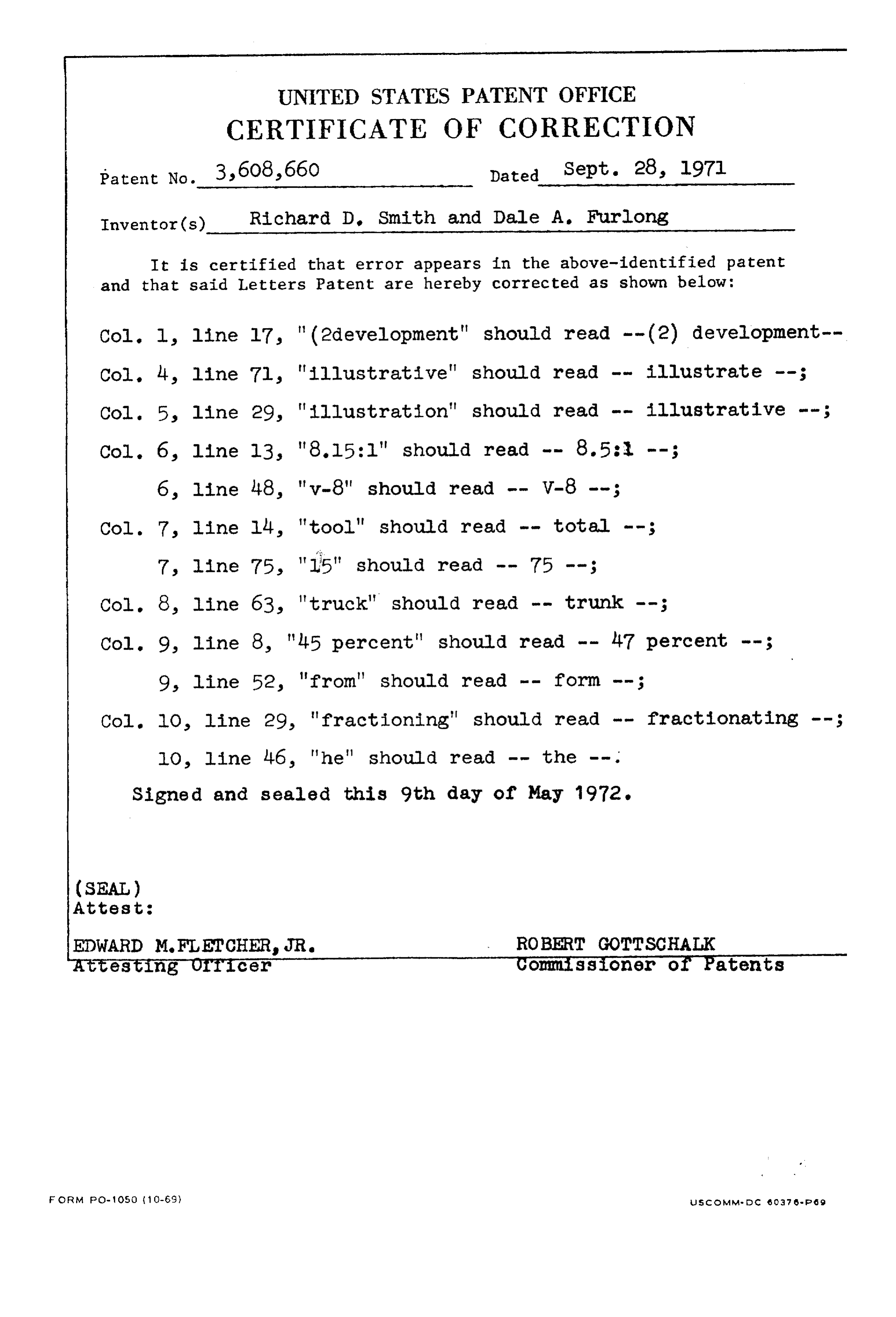
UNITED STATES PATENT OFFICE
CERTIFICATE OF CORRECTION
Inventor(s) Richard D. Smith and Dale A. Furlong It is certified that error appears in the above-identified patent and that said Letters Patent are hereby corrected as shown below:
Col. 1, line l7, " (2development" should read -- (2) development-- Col. 4, line 7l, "illustrative" should read -- illustrate --; Col. 5, line 29, "illustration" should read -- illustrative --;
Col. 7, line lily, "tool" should read -- total --;
Col. 8, line 63, "truck" should read -- trunk --;
Col. 9, line 8, "l-5 percent" should read -- 47 percent --; 9, line 52, "from" should read -- form --;
Col. 10, line 29, "fractioning" should read -- fractionating --; lO, line 46, "he" should read -- the -- .
Signed and sealed this 9th day of May 1972.
(SEAL)
Attest:
EDWARD M.FLETCHER, JR. ROBERT GOTTSCHALK 5testing OTTicer Comissioner of Patents
FORM foo-1 Oso (10-69) usic dim Med c. 6037 es-P6 g
Provenance
- Collection
- Cited prior art
- Original PDF
- patentimages.storage.googleapis.com →
- Filed
- 1969-02-03
- Pages
- 14
- Method
- pdftotext (the PDF's own text layer) + pdftoppm 300dpi page scans
- Source
- Google Patents bibliographic record
- Granted
- 1971-09-28
- Inventors
- Richard D Smith; Dale A Furlong; Combustion Power Co Inc
- Transcribed from
- patentimages.storage.googleapis.com →