patent · US5289690
Refrigerant recycling system
1 March 1994
Page 1 — bibliographic record
United States Patent (19) 11) Patent Number: 5,289,690 Rockenfeller et al. (45) Date of Patent: 'Mar. 1, 1994 (54) REFRIGERANT RECYCLING SYSTEM 4,343,629 8/1982 Dinsmore et al. ...................... 55/28 75 Inventors: Uwe Rockenfeller; Lance D. Kirol, 4,723,595 2/1988 Yasunaga et al....... 165/104.12 5,165,247 l. 1/1992 Rockenfeller et al. ................. 62/77 both of Boulder City, Nev.
Primary Examiner-Henry A. Bennet (73) Assignee: Rocky Research, Boulder City, Nev. Assistant Examiner-William C. Doerrler * Notice: The portion of the term of this patent Attorney, Agent, or Firm-Jerry R. Seiler subsequent to Nov. 24, 2009 has been (57) ABSTRACT disclaimed.
(21) Appl. No.: 925,995 The invention disclosed herein relates to an apparatus for being detachably connected to a chemical or refrig (22) Filed: Aug. 6, 1992 eration system for selectively receiving and dispensing a gaseous refrigerant or chemical from and to that system,
Related U.S. Application Data respectively, including a vessel having a chamber capa 63 Continuation of Ser. No. 653,768, Feb. 11, 1991. ble of maintaining a pressurized gas therein, gas inlet 51) Int. Cl.......................... F28D 7/00; F28D 17/00 means for directing the gas: to and from the chamber, 52) U.S.C. .......................................... 62/77; 62/475; and connection means for connecting the gas inlet to a 62/480; 134/21; 134/31; 141/65; 141/110; refrigeration or chemical system; a plurality of heat 96/146; 95/128 exchange conduits exposed in the chamber for directing 58) Field of Search ................... 62/77, 475, 480, 112, heat exchange fluid therethrough and fluid inlet and 62/292, 304; 55/25, 28, 70,208; 134/21, 31; outlet means communicating exteriorly of the vessel for 141/65, 66, 110 directing the fluid to and from the conduits, respec
tively; and a solid adsorbent capable of alternately ad sorbing and desorbing the gaseous refrigerant or chemi
2,215,323 9/1940 Guthrie ................................. 55/208 of the heat exchange conduits.
4,007,606 2/1977 Yoshio .............. ... 62/475 4,056,369 11/1977 Quackenbush .......................... 55/58 27 Claims, 1 Drawing Sheet
Page 2
Drawing sheet — no readable text.
Page 3
be useful in broader applications, as will be explained
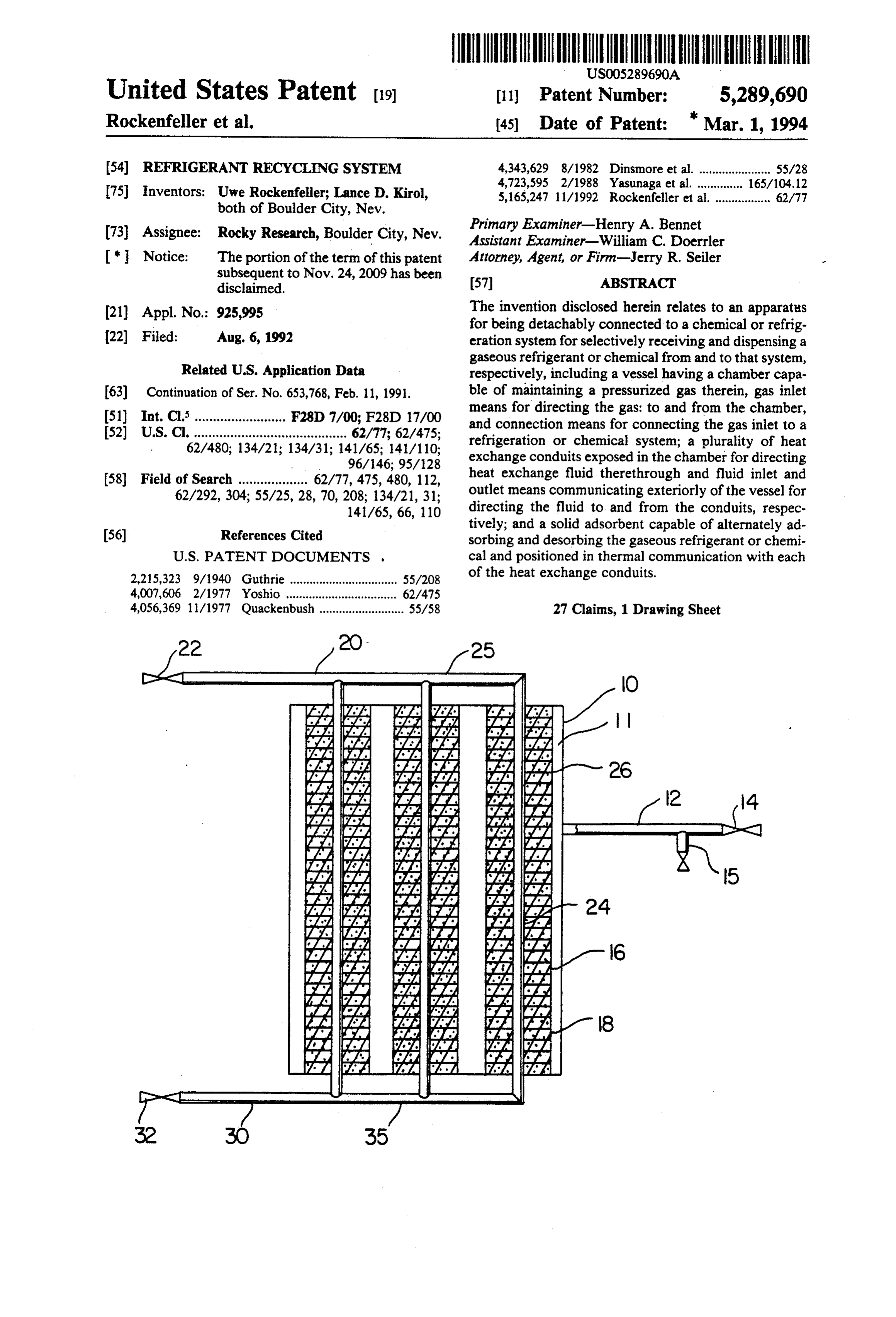
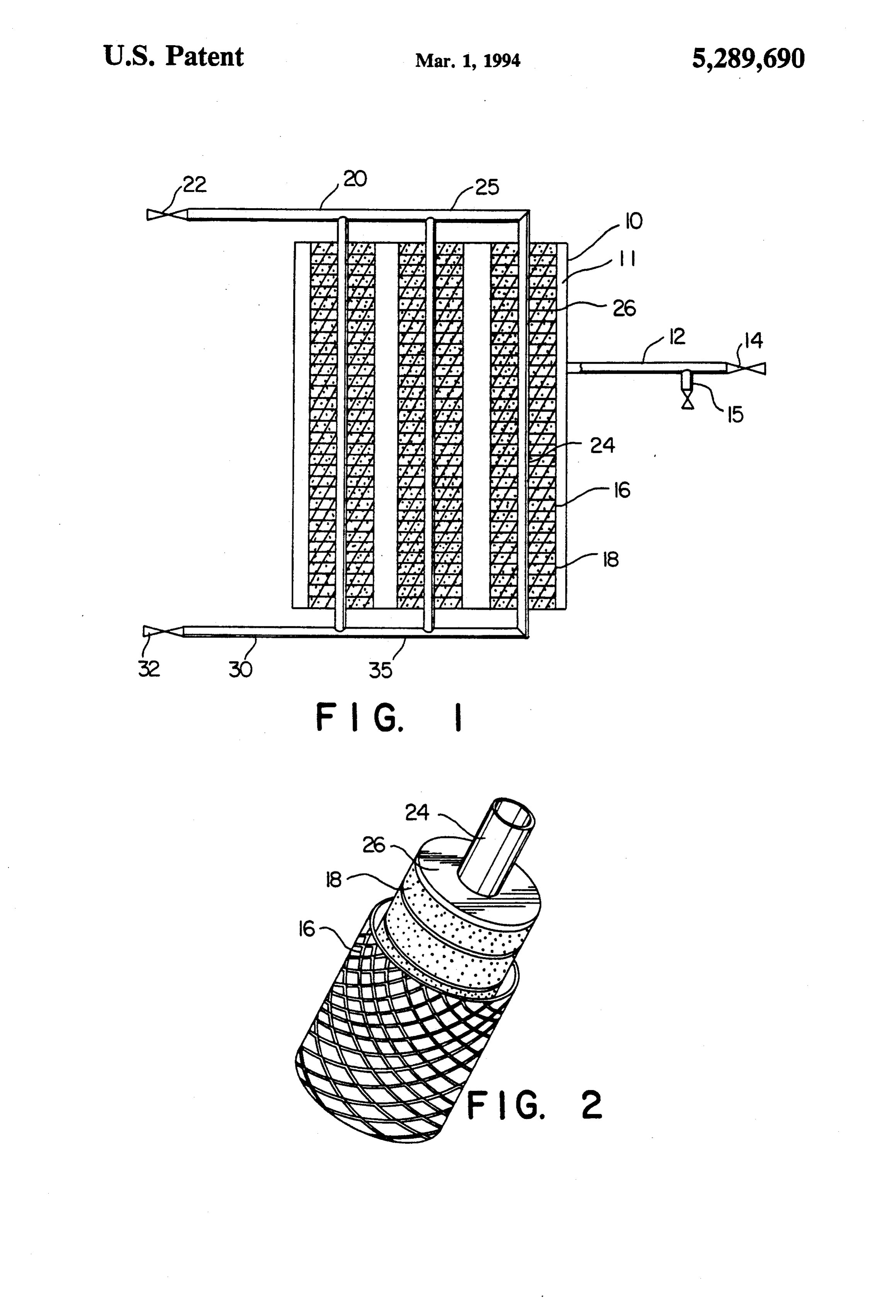
REFRIGERANT RECYCLING SYSTEM hereinafter. Referring to FIG. 1, there is shown a sche matic illustration of the components and features of an
This application is a continuation of U.S. application apparatus of the invention. The vessel 10 defines an Ser. No. 07/653,768, filed Feb. 11, 1991. s interior chamber 11 capable of maintaining a pressur BACKGROUND OF THE INVENTION ized gas. Within the interior chamber are a plurality of conduits or pipes 24 which extend exteriorly of the
The collection or capture of gaseous refrigerants to vessel to be connected to a source of heat exchange be evacuated from refrigeration systems is often not fluid, typically water. Any number of interior pipes may practiced due to the lack of suitable available commer 10 be used, depending on the size of the vessel, with the cial equipment or convenient methods. Although the latter being of a number and size depending on the use of fluorocarbon or CFC refrigerants are intended to amount of refrigerant gas which is to be received and be gradually phased out because of atmospheric and adsorbed when the system is used. The plurality of heat environmental pollution, even with the use of other exchange pipes 24 are secured to a common inlet header gaseous refrigerants including hydrogen, nitrogen or 15 or manifold 25 which may be interior or exterior to the polarized gaseous refrigerants such as ammonia, water, vessel wall 10. Secured to header 25 is an inlet pipe 20 methanol, methylamine, sulfur dioxide, and the like, and valve 22 for being attached to a source of heat release of such materials into the atmosphere is environ exchange fluid. The inclusion of valve 22 on the inlet mentally and economically undesirable and may be line is optional, and instead, a coupling or connection prohibited by law. Similarly, the temporary evacuation 20 means for simply securing the inlet pipe to a source of or purging of toxic gases from chemical systems to hot or cold water, which source is usually valved, is avoid atmospheric pollution, or to prevent the loss of also suitable. Each of the heat exchange pipes is also valuable or expensive gases, are of substantial interest, connected to an outlet header or manifold 35 interiorly but practical systems for such uses are not presently or outside of the vessel walls. The manifold is con available. 25 nected to an exterior pipe or outlet line 30, which also SUMMARY OF THE INVENTION may be provided with a valve 32.
A refrigerant gas inlet pipe 12, which also may have
The system of the present invention is directed to an a valve 14 and/or coupling means for securing the inlet apparatus for being permanently or selectively installed pipe to a refrigeration system line or conduit, extends with a refrigeration or chemical system whereby a gas 30 exteriorly of the vessel 10 and provides the passageway may be evacuated from the system and adsorbed on a for introducing and discharging a gaseous refrigerant to solid adsorbent material, and later desorbed and re and from the apparatus. The refrigerant gas inlet pipe 12 turned to the system, if and when desired. In one em communicates with the interior chamber 11 of the ves bodiment, the invention comprises a portable system sel 10 so that the refrigerant gas may be directly intro incorporating a pressure holding vessel for adsorbing 35 duced into the vessel when the valve or connection the gas therein and includes means for selectively de means is tapped into a gas line of a refrigeration system. sorbing the gas for return to the refrigeration or chemi Also shown extending from inlet pipe 12 is an accessory cal system. In another embodiment, the invention com conduit or nipple 15, which may be provided with a prises a vessel having the gas adsorbing and desorbing valve or other shut-off means, for securing a pressure capability which may be permanently installed with a line from a pump or compressor. Although an accessory system for selectively capturing the gas and for return compressor or pump or other source of pressurizing the ing it to the system when desired. vessel may be installed as component of the apparatus, The advantages of a system and apparatus of the it is an optional feature since it may not be necessary to present invention include providing means for evacuat utilize pressure or suction assist where the refrigeration ing the gas from a refrigeration or chemical system, for system to which the apparatus is connected has suffi example, when a leak is detected or during repair or cient compressor capacity or where sufficiently high modification of the system during which removal of the temperature heat can be supplied to the vessel to raise gas is desired. Such evacuation may be initiated auto the temperature.
matically utilizing suitable monitoring and valve engag Secured in heat exchange communication with each ing means, or accomplished manually. These, as well as 50 of the pipes 24 is solid adsorbent 18 capable of alter other features and advantages of the invention, will be nately adsorbing and desorbing gaseous refrigerant. evident from the following detailed description. The solid adsorbent is preferably fixed or positioned BRIEF DESCRIPTION OF THE DRAWINGS around and in contact with the heat exchange pipes as disclosed in co-pending application Ser. No. 07/320,652
FIG. 1 is a schematic view of the interior of an appa 55 filed Mar. 8, 1989, the description of which is incorpo ratus according to the invention illustrating components rated herein by reference. Preferably, the pipes include and features thereof; and heat transfer projections in the form of plates, fins, FIG. 2 is a partial view of an example of a heat ex trays, or the like extending from and preferably at change conduit as used in the apparatus with solid ad tached along the length of each of the heat exchange sorbent disposed in heat exchange relationship with the 60 pipes for improving heat exchange between the heat conduit. exchange fluid passing through the pipes and the adsor DETAILED DESCRIPTION OF THE bent material. Extending around the exterior of the solid INVENTION adsorbent is a barrier 16 for retaining the solid adsor bent particles or mass in place around the pipes and in
Although the present invention will be primarily 65 contact with the heat exchange plates or surfaces. It is described for the capture of gaseous refrigerants, partic important that this barrier material be porous to allow ularly polarized gases, and especially ammonia, from the passage of the gaseous refrigerant to and from the refrigeration systems, it is to be understood that it may adsorbent. For this purpose, the barrier material may be
Page 4
wire mesh, porous foam or refractory material, inert tor means 14 is connected to the refrigerant loop system fabric, and the like. An example of the heat exchange at any suitable point, the heat exchange fluid inlet pipe pipes on the interior of the apparatus is illustrated in 20 connected to a source of cooling heat exchange fluid, FIG. 2, showing a heat exchange pipe having a plurality for example, water, and the outlet pipe 30 connected to of fins 26 extending therearound, with solid adsorbent a heat exchange fluid discharge receiving means or 18 located between the fins and further surrounded by a drain. After the cooling heat exchange fluid has been mesh or gaseous permeable fabric 16. The embodiment passed through the heat exchange pipes for a time suffi shown is only one example of such a construction, and cient to cool the solid adsorbent to the desired tempera other ways and means for designing the shape of the ture, valve 4 or other means for communicating the heat exchange pipes within the interior of the apparatus 10 refrigeration system line to the gas inlet line 12 is and for positioning the solid adsorbent and heat ex opened. Because the adsorption reaction of the gaseous change communication with the pipes in such a manner refrigerant with the solid adsorbent is exothermic, it is that the gaseous refrigerant introduced into the vessel is necessary or preferred to maintain an approximately readily exposed to the adsorbent may be used within the constant temperature of the solid adsorbent during the purview of the invention for achieving the desired pur 15 time that the gaseous reactant is being introduced and pose and results. adsorbed. By way of example, where ammonia is to be The specific solid adsorbent or adsorbents used adsorbed on a solid adsorbent, for example, SrCl2, cool within the apparatus will depend on the nature of the ing fluid temperature ranges of between about 0' C. and gas to be received and adsorbed. Where polar gases about 25 C. at atmospheric pressure are used. The such as ammonia, water, sulfur dioxide, lower alkanols, 20 pressure within the adsorbent vessel may be adjusted as alkylamines, polyamines or phosphine are to be re desired using the compressor of the refrigerant system ceived, preferred solid adsorbents include metal oxides, being evacuated, or using an accessory compressor as halides, carbonates, nitrates, nitrites, sulfates, oxalates, previously described, or both. It will be understood that or sulfides capable of forming coordinative bonds with during adsorption, higher pressures will decrease the the refrigerant. Particularly suitable for such solid ad 25 time requirements needed for adsorbing the gaseous sorbents are those in which the metal of the salt is se refrigerant. The pressure of refrigerant systems encoun lected from the group consisting of alkali or alkaline tered are typically between about 0.2 and about 20 bars, earth metals, transition metals, aluminum, zinc, cad and often around 3 bars. During the adsorption, the mium or tin. Preferred adsorbents are capable of ad pressure of the refrigerant in the system is reduced as sorbing gaseous refrigerant at between about -30° C. 30 adsorption occurs.
and about 60° C., and can adsorb an amount of refriger After the refrigerant has been effectively evacuated, ant corresponding to at least about 25% of the weight of the valve means between the refrigeration system and the compound. the apparatus of the invention is closed, flow of heat Of particular interest are the solid adsorbents for exchange fluid into the apparatus terminated, and if creating complex compounds for use with ammonia 35 desired, the apparatus may be disconnected. Thereafter, refrigeration systems. For that purpose, the solid adsor the apparatus may be stored with the refrigerant gas bent salts and complex compounds disclosed in U.S. adsorbed on the solid adsorbent until it is desired to be Pat. No. 4,848,944, the description of which is incorpo recharged into the system from which it was removed rated herein by reference, are particularly desirable. or charged into another system.
Within those groups, the preferred complex compounds 40 When recharging of a refrigerant system is desired, comprise chlorides, bromides, sulfates and chlorates of the gas refrigerant inlet line 12 of the apparatus is se metals selected from the group consisting of alkali and cured into the refrigerant system line where desired, alkaline earth metals, chromium, manganese, iron, co while heat exchange fluid is introduced into the heat balt, nickel, cadmium, tantalum, and rhenium or double exchange pipes of the apparatus. During this phase of metal chloride salts. The preferred ammonia/salt com 45 using the apparatus, the adsorbed refrigerant, is de plex compounds are those having an equilibrium tem sorbed from the solid adsorbent by heating the solid perature at 1 bar pressure at least 20 C. higher than the adsorbent, thereby increasing the vapor pressure of the ammonia equilibrium temperature, and not greater than adsorbed, gaseous refrigerant. If desired, the rate of the about 160° C. Most preferred ammoniated complex endothermic desorption reaction may be increased by compounds used in the apparatus of the invention are reducing the pressure in the chamber of the vessel, for those selected from the group consisting of CaCl2.4-8 example, by pulling a suction on gas pipe 12 utilizing the (NH3), SrCl2.1-8 (NH3), CaBr2. 2-6 (NH3), SrBr3,0-8 vacuum side of an accessory compressor and/or the (NH3), and LiCl,0-3 (NH3). Mixtures of these com suction may be pulled from the compressor of the re pounds may also be used. The solid adsorbent composi frigeration system in which the gaseous refrigerant is tion may also comprise a mixture of the complex com 55 being introduced. Again, constant temperatures of the pound and a solid inert material such as pumice, alumina heating fluid for desorbing the gaseous refrigerant is silica, porous metal granulates, etc., especially porous preferred. In an example using ammonia adsorbed on and highly thermally conductive materials. SrCl2, desorption temperatures of the heat exchange Where non-polar gases are to be adsorbed, zeolites or fluid and solid adsorbent between about 5 C. and about activated carbon may be used. Metal hydrides are useful 150° C. and preferably about 30° C. and about 125 C. for the adsorption of hydrogen used in certain refrigera are suitable. The use of a compressor for creating a tion and chemical systems known in the art. suction in the line during the feedback of the gas into In operating a method utilizing the apparatus of the the refrigerant loop may not be required, although it invention for receiving a gaseous refrigerant from a should be understood that the lower the system pressure refrigeration system in which the refrigerant is to be 65 during desorption, the faster the rate of desorption. withdrawn, for example, when necessary for repairs to It has been found utilizing apparatus according to the the refrigeration system or its equipment, compressors, invention for ammonia adsorption and desorption with pumps, lines, and the like, the inlet pipe 12 and connec SrCl2 as the solid adsorbent, depending on pressure and
Page 5
temperature conditions, each adsorption and desorption chemical may be adsorbed along substantially all of phase can be completed in between about 15 minutes said conduits, and fluid inlet and outlet means com and about 2 hours. Again, lower cooling temperatures municating exteriorly of said vessel for directing during adsorption and higher heating temperatures dur said heat exchange fluid to and from substantially ing desorption accelerate the reaction to provide faster all said conduits during said adsorption, and for and more dramatic pull-down, or faster and higher directing a heat exchange fluid to and from sub pressure ammonia recycling, respectively. Of course, stantially all said conduits during said desorption. the heating and cooling of the solid adsorbentbed of the 2. Apparatus of claim 1 wherein heat exchange fluid apparatus will depend on the temperature of the heat for adsorption is at a first temperature and for desorp exchange fluid available at the site. O tion is at a second temperature. It is also within the purview of the invention that the 3. Apparatus capable of receiving a polar chemical apparatus be portable, where desired or otherwise con from a system containing said polar chemical, storing venient so that it may be moved to different refrigera said polar chemical for a selected time, and selectively tion equipment or chemical sites for being connected to dispensing said polar chemical to said system compris evacuate refrigeration or chemical loops as it is needed. 5 ling:
For example, portable systems incorporating reactors a vessel having a pressure sealed chamber and gas capable of adsorbing up to 1,000 lbs. of refrigerant may inlet means for being connected to said system be especially useful. In other locations, especially where containing said polar chemical, very large gas containing systems are installed, it may a solid absorbent salt capable of forming a complex be preferred to permanently locate such an apparatus 20 coordinated compound with said polar chemical for evacuating and recharging (recycling), whereby the which compound is capable of adsorbing at least apparatus of the invention need not be portable or 25% of said polar chemical, by weight of said com moveable to any substantial extent. It may also be desir pound, and able to incorporate a gas detector with the system such heat exchange means exposed in said sealed chamber that adsorption may be triggered by monitoring the 25 comprising a plurality of heat exchange conduits atmosphere adjacent the refrigeration system for indi substantially all of said conduits having said solid cating a leak and by removal of gas where such a leak is absorbent secured thereon whereby said polar detected. Such equipment may include valves automati chemical may be adsorbed along substantially all of cally actuated in response to a detected gas leak for said conduits, a fluid inlet and a fluid outlet, said initiating a cool water supply into the heat exchange 30 fluid inlet including means for being connected to a conduit of the apparatus and for opening the valve to fluid supply source for directing a heat exchange begin withdrawing the gas, as previously described. fluid through substantially all said conduits for Such equipment may be especially useful where injury adsorbing said polar chemical and for directing a to humans or expensive damage to products or materials heat exchange fluid through substantially all of said could result in the event of significant exposure to leak 35 conduits for desorbing said polar chemical. ing gases. These, as well as other modifications and 4. Apparatus of claim 3, wherein said heat exchange advantages of the components of the invention and uses fluid for absorbing said polar chemical has a relatively thereof, will be evident to those skilled in the art. low temperature, and said heat exchange fluid for de What is claimed: sorbing said polar chemical has a relatively high tem 1. Apparatus for being detachably connected to a 40 perature.
system containing a chemical and capable of selectively 5. A method of removing a chemical in a gaseous evacuating said chemical in a gaseous state from said state from a chemical system having a gas line and pres system, storing said chemical for a selected time, and surized with said gas, utilizing an apparatus comprising selectively charging said chemical to said system, com a vessel having a chamber capable of maintaining a prising: 45 pressurized gas therein, gas inlet means for directing a vessel having a chamber capable of maintaining a gaseous chemical to and from said chamber, and con pressurized gas therein, gas inlet means for direct nection means for connecting said gas inlet to a chemi ing gaseous chemical to and from said chamber, cal system containing said chemical, a solid absorbent and connection means for connecting said gas inlet comprising a metal salt capable of forming a complex to a chemical system containing said chemical, 50 compound with said gaseous chemical which is capable a solid adsorbent comprising a metal salt capable of of alternatively absorbing and desorbing said gaseous forming complex compound with said gaseous chemical and secured in heat exchange communication chemical which is capable of alternatively absorb with a plurality of heat exchange conduits, said metal ing and desorbing said gaseous chemical, said metal salt comprising a metal halide, oxide, sulfate, sulfite, salt comprising a metal halide, oxide, sulfate, sul 55 nitrate, nitrite or oxalate in which the metal is an alkali fite, nitrate, nitrite or oxalate in which the metal is metal, alkaline earth metal, transition metal, aluminum, an alkali metal, alkaline earth metal, transition or zinc, metal, aluminum, or zinc, a double metal salt in which the two metals are se a double metal salt in which the two metals are se lected form strontium, sodium, aluminum, silver, lected from strontium, sodium, aluminum, silver, 60 gold, calcium, magnesium and cobalt, gold, calcium, magnesium and cobalt, ammonium chloride, or ammonium chloride, or a double metal salt in which one metal is an alkali or a double metal salt in which one metal is an alkali or alkaline earth metal, and alkaline earth metal, and a plurality of heat exchange conduits exposed in said a plurality of heat exchange conduits exposed in said 65 chamber for directing heat exchange fluid there chamber for directing heat exchange fluid there through and fluid inlet and outlet means communi through, substantially all of said conduits having cating exteriorly of said vessel for directing said said solid absorbent secured thereon whereby said heat exchange fluid to and from said conduits dur
Page 6
ing said adsorption and said desorption, said polar gaseous chemical from said complex com method comprising: pound, and directing said desorbed polar gaseous connecting said gas inlet means of said apparatus to a chemical to said system. gas line of said system, connecting the fluid inlet 8. A method of supplying a chemical system with a means of said apparatus to a source of cooling fluid 5 chemical, in a gaseous state, utilizing an apparatus con having a temperature between about -30 C. and prising a vessel having a chamber capable of maintain about 60 C, and ing a pressurized gas therein, gas inlet means for direct concurrently introducing said gas from said system ing gaseous chemical to and from said chamber, and into said chamber of said apparatus while directing connection means for connecting said gas inlet to a said cooling fluid through said heat exchange con 10 chemical system, a solid adsorbent comprising a metal duits, and adsorbing said gaseous chemical on the salt capable of forming a complex compound with said solid absorbent in an exothermic absorption reac gaseous chemical which is capable of alternatively ad tion while continuing to direct cooling fluid sorbing and desorbing said gaseous chemical and se through said heat exchange conduits. cured in heat exchange communication with a plurality 6. A method of removing ammonia from a chemical 15 of heat exchange conduits, said metal salt comprising a system utilizing an apparatus comprising a vessel having metal halide, oxide, sulfate, sulfite, nitrate, nitrite or pressure sealed chamber and a gas inlet means for being oxalate in which the metal is an alkali metal, alkaline connected to said system containing said ammonia, a earth metal, transition metal, aluminum, or zinc, solid absorbent salt capable of forming a complex coor a double metal salt in which the two metals are se dinated compound with said ammonia, which com 20 lected form strontium, sodium, aluminum, silver, pound is capable of absorbing at least 25% ammonia, by gold, calcium, magnesium and cobalt, weight of said compound, and wherein said salt is se ammonium chloride, or cured tin heat exchange communication with the exte a double metal salt in which one metal is an alkali or rior of each of a plurality of heat exchange conduits, alkaline earth metal, and and heat exchange means exposed in said sealed cham 25 said solid adsorbent having said chemical adsorbed ber comprising a plurality of heat exchange conduits thereon and capable of being desorbed therefrom, a and having a fluid inlet and a fluid outlet, said fluid inlet plurality of heat exchange conduits exposed in said including means for being connected to a fluid supply chamber from directing heat exchange fluid there source for directing a heat exchange fluid through said through, and fluid inlet and outlet means communi conduits, said method comprising: 30 cating exteriorly of said vessel for directing said feeding ammonia from said system to the sealed heat exchange fluid to and from said conduits, said chamber of said apparatus and concurrently sup method comprising:
plying cooling fluid at a temperature of between connecting the fluid inlet means of said apparatus to a about -30° C. and about 60° C. through the heat source of heating fluid having a temperature suffi exchange conduits of said apparatus whereby said 35 cient to induce desorption of said chemical in a ammonia is adsorbed on said salt in an exothermic gaseous state from said solid adsorbent, connecting reaction, the gas inlet means of said apparatus to a source of continuing to supply cooling fluid through said heat heating fluid having a temperature sufficient to exchange conduits while feeding ammonia into said induce desorption of said chemical in a gaseous pressure sealed chamber, and state from said solid adsorbent, connecting the gas selectively terminating said ammonia removal by inlet means of said apparatus with a gas line of said disconnecting communication between said sealed chemical system, directing said heating fluid chamber and said refrigeration system and termi through said heat exchange conduits to desorb said nating the supply of cooling fluid through said heat chemical from said solid adsorbent, and supplying exchange conduits of said apparatus. 45 said desorbed chemical to said chemical system. 7. A method of supplying a polar gaseous chemical to 9. Apparatus of claim 1 wherein said heat exchange a system utilizing an apparatus comprising a vessel hav conduits include heat exchange surfaces extending from ing a pressure sealed chamber, gas outlet means for the exterior of said conduits in said chamber. directing polar gaseous chemical from said chamber, 10. Apparatus of claim 9 wherein said heat exchange connection means for connecting said gas outlet to said 50 surfaces comprise fins.
system, a complex compound comprising a reaction 11. Apparatus of claim 9 wherein said solid adsorbent production of said polar gaseous chemical and a metal is secured adjacent the exterior of said conduits in salt capable of alternately adsorbing and desorbing said contact with said heat exchange surfaces. polar gaseous chemical thereon, said complex com 12. Apparatus of claim 1, wherein said solid adsor pound secured in heat exchange communication with a 55 bent is capable of adsorbing said polar gaseous chemical plurality of heat exchange conduits exposed in said at a temperature of between about -30° C. and about chamber for directing heat exchange fluid there 60 C.
through, and fluid inlet and outlet means communicat 13. Apparatus of claim 1 wherein said gaseous chemi ing exteriorly of said vessel for directing said heat ex cal is ammonia and said solid adsorbent is a complex change fluid to and from said conduits, said method compound of ammonia and a metal salt having an equi comprising: librium temperature at 1 bar pressure at least 20° C. connecting said gas inlet means of said apparatus with higher than the ammonia equilibrium temperature, and said system, connecting the fluid inlet means of said not greater than about 160 C.
apparatus to a source of heat exchange fluid having 14. Apparatus of claim 1 including a porous, inert a temperature sufficient to induce desorption of 65 solid material mixed with said solid adsorbent. said polar gaseous chemical from said complex 15. Apparatus of claim 3, wherein said polar chemical compound, directing said heat exchange fluid is ammonia and said salt comprises a metal halide, oxide, through said heat exchange conduits to desorb said sulfate, sulfite, nitrate, nitrite or oxalate in which the
Page 7
metal is an alkali metal, alkaline earth metal, transition conduits, and thereafter selectively charging a chemical metal, aluminum, or zinc; system with said gas comprising connecting the fluid a double metal salt in which the two metals are se inlet means of said apparatus to a source of heating fluid lected from strontium, sodium, aluminum, silver, having a temperature sufficient to induce desorption of gold, calcium, magnesium and cobalt; said gas from said solid adsorbent opening the gas inlet ammonium chloride; and means, directing said heating fluid through said heat a double metal salt in which one metal is an alkali or exchange conduits thereby desorbing said gas from said alkaline earth metal. solid adsorbent in an endothermic reaction, and direct 16. Apparatus of claim 3 wherein said salt comprises ing the desorbed gas to said chemical system while CaCl2, LiCl, CaBr2 or SrBr2, and mixtures thereof. 10 continuing to direct heating fluid through said heat 17. Apparatus of claim 3 wherein said vessel is capa exchange conduits.
ble of holding up to about 1,000 lbs. polar chemical. 24. A method of claim 6 wherein said salt comprises 18. Apparatus of claim 15 wherein said salt comprises SrCl2 and wherein said ammonia is fed into said sealed SrCl2 and said complex coordinated compound com chamber at a pressure of between about 0.2 and about 20 prises SrCl2.X NH3, wherein X is between 1 and 8. 15 atmospheres, and water is supplied to said heat ex 19. Apparatus of claim 3 wherein said heat exchange change conduits at a temperature of between about 0. conduits comprises finned conduits. C. and about 25 C. during said adsorption. 20. Apparatus of claim 3 wherein said heat exchange 25. A method of claim 7 wherein said polar gaseous means includes inlet manifold means for distributing chemical is desorbed from said salt using compressor water from said water inlet to said heat exchange con 20 suction.
duits and outlet manifold means for directing water 26. A method of claim 7 wherein polar gaseous chem from said heat exchange conduits to said outlet. ical is ammonia and said ammonia is desorbed from said 21. Apparatus of claim 3 including a porous, inert salt by supplying a heating fluid through said heat ex solid material mixed with said solid adsorbent. change conduits at a temperature of between about 5 22. Apparatus of claim 3 including valve means coop 25 C. and about 150 C. during said desorption. erating with gas inlet means for selectively directing 27. A method of claim 26 wherein said salt in said polar chemical to and from said sealed chamber. apparatus comprises SrCl2 and wherein said ammonia is 23. The method of claim 5 including closing the gas desorbed by supplying water or steam through said heat inlet means to terminate further introduction of said gas exchange conduits at a temperature of between about 5 into said chamber from said chemical system, terminat 30 C. and about 150 C.sk ing the flow of cooling fluid into said heat exchange k
Provenance
- Collection
- Cited prior art
- Original PDF
- patentimages.storage.googleapis.com →
- Filed
- 1992-08-06
- Pages
- 7
- Method
- pdftotext (the PDF's own text layer) + pdftoppm 300dpi page scans
- Source
- Google Patents bibliographic record
- Granted
- 1994-03-01
- Inventors
- Uwe Rockenfeller; Lance D. Kirol; Rocky Research Corp
- Transcribed from
- patentimages.storage.googleapis.com →