patent · US5113659
Solar thermal energy receiver
19 May 1992
Page 1 — bibliographic record
United States Patent (19) 11 Patent Number: 5,113,659 Baker et al. 45) Date of Patent: May 19, 1992 (54). SOLAR THERMAL ENERGY RECEIVER Primary Examiner-Allen M. Ostrager Attorney, Agent, or Firm-James A. Mackin; Gene E.
75) Inventors: Karl W. Baker, Akron; Miles O. Shook; Guy M. Miller
Dustin, North Olmsted, both of Ohio 73) Assignee: The United States of America as 57 ABSTRACT represented by the Administrator of A plurality of heat pipes in a shell receive concentrated the National Aeronautics and Space solar energy and transfer the energy to a heat activated Administration, Washington, D.C. system. To provide for even distribution of the energy 21 Appl. No.: 676,910 despite uneven impingement of solar s R t o pipes, absence of solar energy at times, or failure of one (22 Filed: Mar. 27, 1991 or more heat pipes, energy storage means are disposed 51 Int. Cl. ...... w a a a sa e 8 FO3G 6/00 on the heat pipes which extend through a heat pipe 52) U.S. C. ..................................... 60/641.8; 60/659; thermal coupling means into the heat activated device. 126/433; 126/436 To enhance energy transfer to the heat activated de 58 Field of Search ............................... 126/433,436; vice, the heat pipe coupling cavity means may be pro 60/641.8-641.15, 659 vided with extensions into the device. For use with a 56) References Cited Stirling engine having passages for working gas, heat transfer members may be positioned to contact the gas
4,335,578 6/1982 Osborn et al. ..... ... 60/641.8 tions by transverse walls. To prevent cavity workihg
"...,t fluid from collecting to the extensions, a porous body is 4,706,740 11/1987 Mahefkey ...... E. positioned in the cavity.
4,715, 183 12/1987 Meijer et al........................... 60/524 4,738,304 4/1988 Chalmers et al. ..................... 165/13 19 Claims, 4 Drawing Sheets
22 23 4 - a
Page 2
Drawing sheet — no readable text.
Page 3
Drawing sheet — no readable text.
Page 4
Drawing sheet — no readable text.
Page 5
Drawing sheet — no readable text.
Page 6
emission characteristics, Wedged grooves along the
SOLAR THERMAL ENERGY RECEIVER interior of the radiator cavity enhance condensation and allow for the rapid return of the working fluid to the
The invention described herein was made by employ 5 U.S. Pat. No. 4,715, 183 to Meijer et al discloses an ees of the United States Government and may be manu external heating system for a heat engine such as a Stir factured and used by or for the Government for govern ling engine, which system permits thermal energy to be mental purposes without the payment of any royalties provided by solar energy or fuel combustion sources. In thereon or therefor. order that either source may be employed, there is pro 10 vided a complexly shaped heat pipe evaporator section
TECHNICAL FIELD having an enclosed cavity for receiving solar energy This invention relates to solar heat collectors and is and another section forming hollow fins, the section directed more particularly to a solar heat management being exposed to hot combustion gases. system which collects, stores and evenly distributes U.S. Pat. No. 4,738,304 to Chalmers et al discloses a solar heat to a utilization device such as a Stirling en 15 heat radiator having multiple heat pipes. Sensors moni gine, for example. tor the flow of heat transfer fluids in each of the pipes Space vehicles generally rely on batteries and/or and control respective valves in each of the pipes. A solar cells to provide needed electrical power. Such sudden reduction in flow in one of the pipes would devices produce d-c electrical power which requires indicate a leak and the leaking pipe would be cut out of the use of ancillary electrical equipment such as d-c to 20 the system by closing valves at respective opposite ends d-c converters, inverters or the like to generate a-c of the pipe. Thus, leaks caused in the radiator of a space power or stepped-up d-c voltages. Additionally, solar vehicle by impacting particles can be isolated to prevent cell arrays, depending on the power needed, usually are loss of the system.
very large in area. This parameter creates a drag prob lem for any vehicle orbiting at a distance from earth at 25 SUMMARY OF THE INVENTION which the atmosphere has more than minimal density. In accordance with the invention, multiple heat pipes Thus, solar cell arrays large enough to generate suffi are disposed in an insulated containment shell which has cient d-c power for a space station, for example, would an aperture for receiving concentrated sunlight. Heat produce an unacceptable magnitude of drag.
Large space vehicles such as a space station will use 30 storage tend means are carried on the heat pipes which ex into a heat utilization device such as a Stirling great amounts of electrical power. Studies have shown engine heater that for many applications solar dynamic power systems means and thehead. Disposed between the heat storage have distinct advantages over other space power sys coupling cavity throughengine
Stirling which heater head is a heat pipe the heat pipes extend in tems such as batteries and solar cells. heat exchanging relationship. The heat pipe coupling
Solar heat can provide the energy for various Ran cavity also includes legs which extend kine and Brayton cycle systems to drive a-c generators. into the heater head. Thus, the heat pipe coupling cavity not only
A Stirling engine driving an alternator appears to be transfers one of the best systems. However, it is important that transfer toheat the between the heat pipes, but enhances heat
Stirling engine heater head.
heat be distribution uniformly around the heater head of In a preferred embodiment, finned members are dis a Stirling engine. Thus, failure of one or more of the 40 posed radically outwardly of the cavity legs in good heat pipes of a solar dynamic system or uneven applica heat transfer tion of solar energy to the heat pipes must not signifi and a pair ofcontact both with respective heat pipes adjacent cavity legs. Gas to be heated cantly affect the uniform distribution of heat to the
Stirling engine heater head. Additionally, a heat man passes over the fins.
agement system used with a Stirling engine for a space 45 In an alternate embodiment, tubular members encase vehicle must provide heat in both the sun and shade the heat pipes through the heat coupling cavity and into the heater head. Longitudinal grooves in the outer sur portions of an orbit and be highly reliable. Furthermore, face critical thermal stresses must be eliminated to avoid of the tubular members within the heater head failure. provide heating passages for the Stirling engine work SO ing gas.
BACKGROUND ART
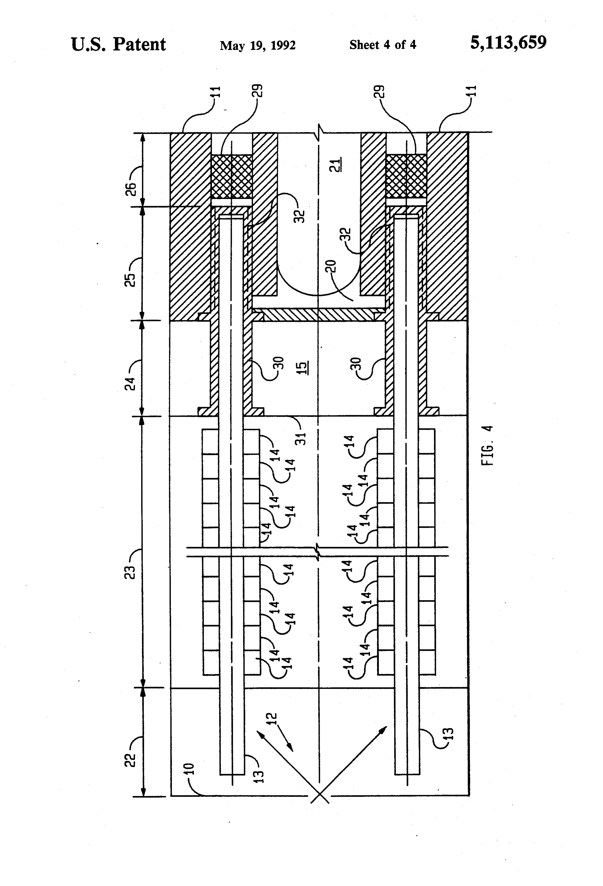
DESCRIPTION OF THE DRAWINGS
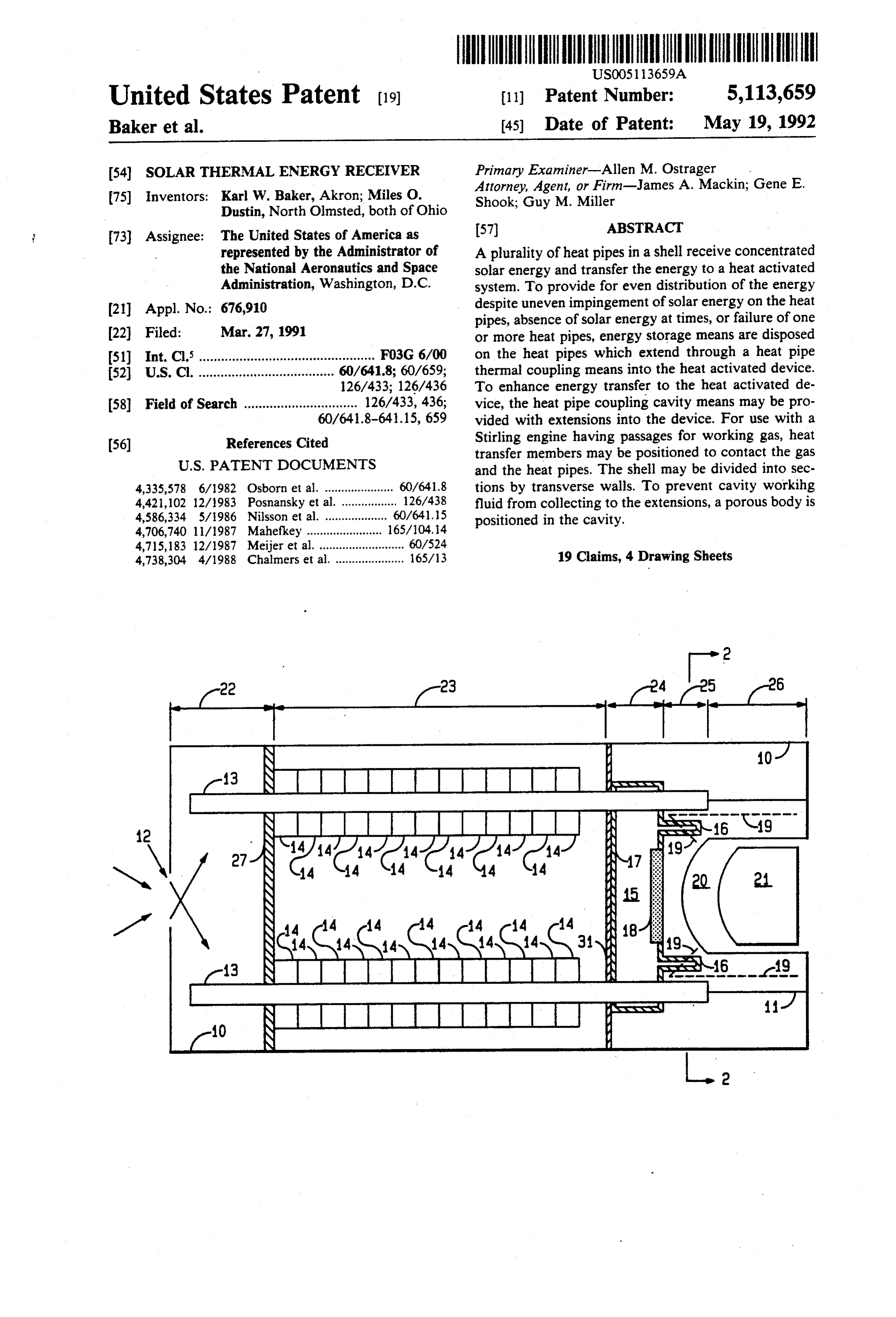
U.S. Pat. No. 4,335,578 to Osborn et al discloses a solar converter which transports solar heat via a sec FIG. 1 is an axial section of a preferred embodiment ondary fluid to a heat exchanger which contains a pri of the solar dynamic power system embodying the in mary working fluid. The secondary fluid is contained in 55 vention;
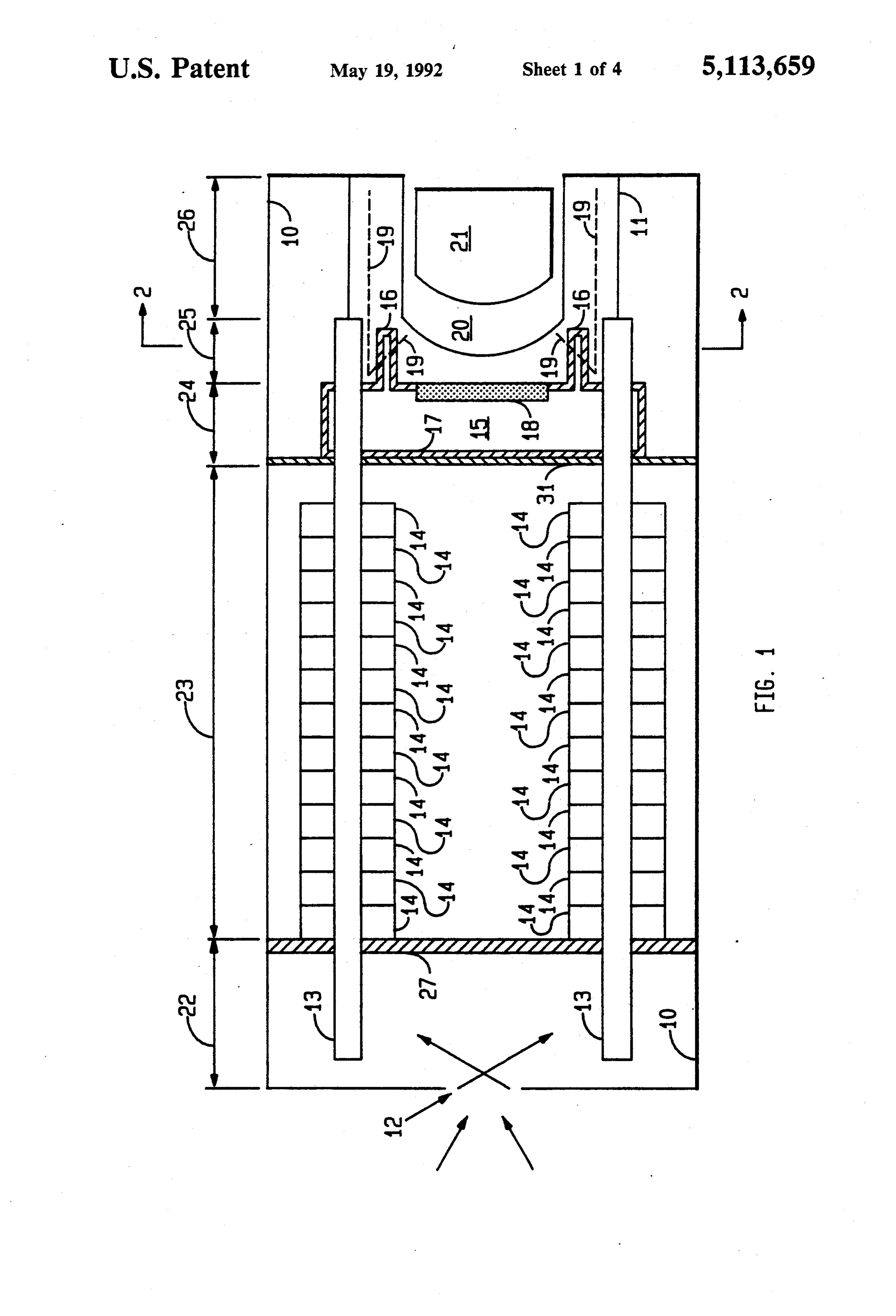
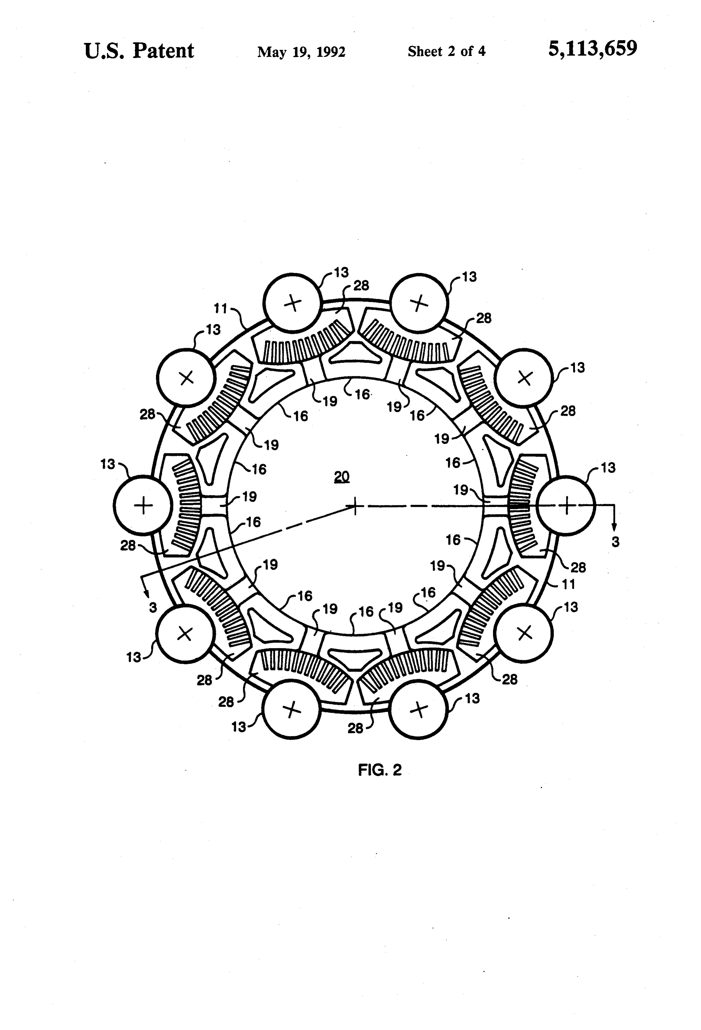
the space between two concentric tubes which com FIG. 2 is a transverse section of the solar heat man prise a solar receiver and is then directed to the heat agement system of FIG. 1 taken along the line 2-2; exchanger. The secondary fluid changes from a vapor FIG. 3 is a partial axial section taken along the line to a liquid in the heat exchanger. 3-3 of FIG. 2; and
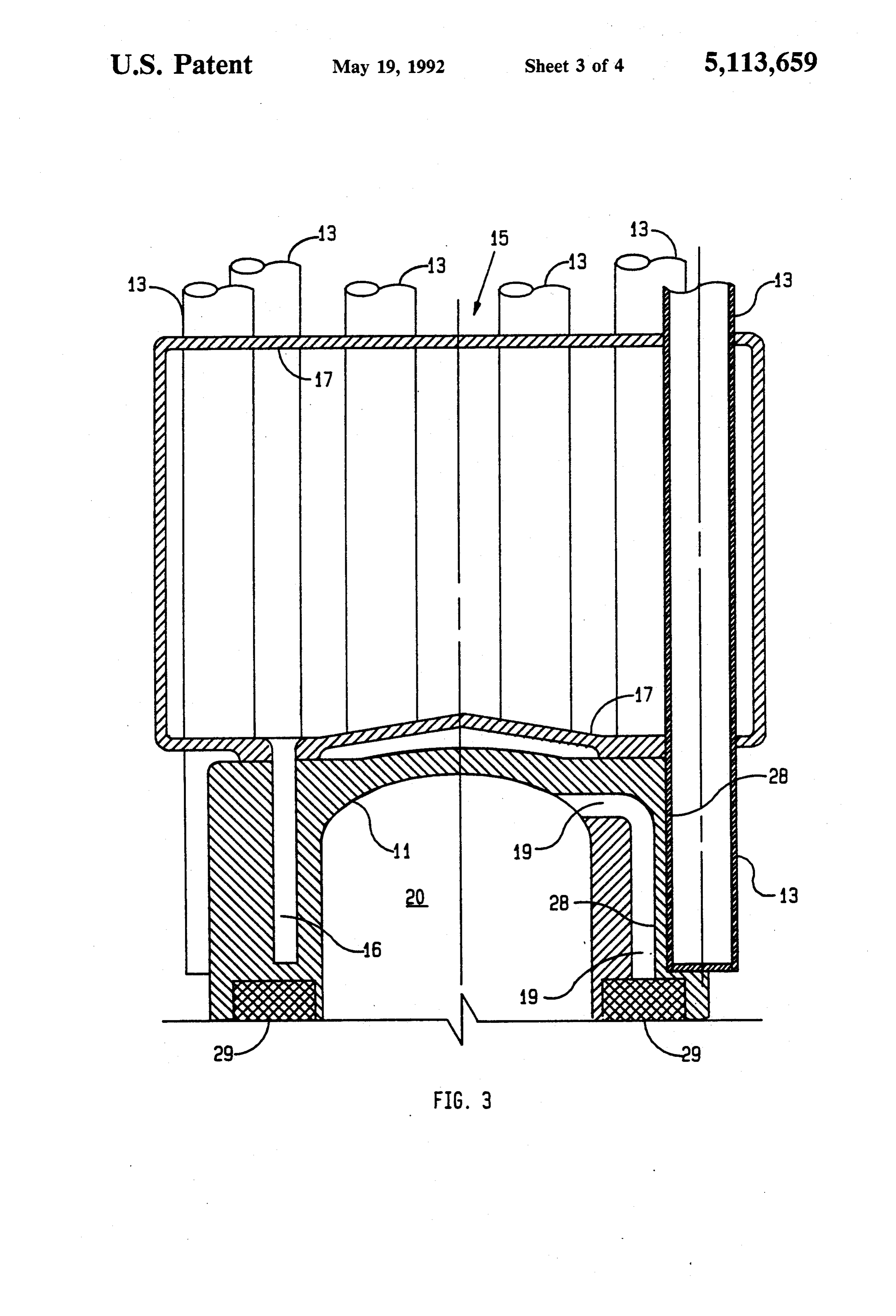
U.S. Pat. No. 4,421,102 to Posnansky et al teaches FIG. 4 is an axial section showing an alternate em that heat distribution in gas containing quartz tubes can bodiment of the invention.
be improved by disposing transparent strips in the tubes, DESCRIPTION OF THE PREFERRED each strip absorbing a portion of solar radiation. EMBODIMENT U.S. Pat. No. 4,706,740 to Mahefkey discloses a vent able survivable heat pipe vapor chamber for disposing 65 Referring now to FIG. 1, there is shown an insulated of excess heat aboard a spacecraft. Multiple heat pipes containment shell 10 having one end attached to a utili utilize a capillary of wicking action between them so zation device such as the heater head 11 of a Stirling that failure of one does not cause a disruption of the heat engine. The other end of the shell 10 includes an aper
Page 7
ture 12 for admitting concentrated sunlight as from a a Stirling engine. Sections 23, 24 and 25 comprise a heat shaped mirror or lens, for example. Thus, the contain processing section.
ment shell 10 is always oriented to maximize the con A transverse wall 31 is attached to cavity 15. The centrated sunlight coming through aperture 12. The wall 31 serves to separate section 23 from section 24 as positioning of the solar dynamic system is effected by well as supporting the heat pipe coupling cavity 15. the space vehicle on which it is carried. Generally the shell 10, heat pipes 13, thermal storage A plurality of heat pipes 13 are disposed in the shell canisters 14, cavity 15 and porous block 18 are all made 10 and extend from its apertured end to engage the of a single material. This provides materials compatibil heater head 11 in heat transfer relationship. Thermal ity which enhances welding and minimizes corrosion. storage canisters 14 are disposed on the heat pipes 13 to 10 FIG. 2 is a transverse cross section of the solar dy provide heat to the heat pipes 13 when insufficient sun namic system of FIG. 1 taken along the line 2-2. Parts light is received through the aperture 12 as would occur in FIG. 2 which are the same parts as in FIG. 1 are during part of the orbit of a space vehicle. identified by numerals which are the same as the numer Heat pipes are well-known and are lined with wick 15 als of FIG. 1. As shown, a plurality of heat pipes 13 are ing material such as wire mesh or screen. The heat pipes 11 at partially each embedded in the cylindrical heater head circumferentially spaced positions.
and screen are made of a high temperature material, To enhance heat transfer from the heat pipes to the such as superalloys or the like or even refractories, Stirling engine working gas, a finned heat transfer mem while the working fluid is Na or K but preferably is Na. ber 28 is disposed at each heat pipe in heat transfer The heat pipe coupling cavity 15 is cylindrical and contact with a significant portion of the circumference parallel to shell 10 with a diameter much grater than its 20 of the heat pipe. The heat transfer member may be made height. Because the cavity 15 contains working fluid and wicking 17 it is essentially a heat pipe and, because of any material having high thermal conductivity and a of its disproportionately small height or thickness to coefficient of expansion which will not cause unaccept diameter ratio, may be termed a squat heat pipe. Its 25 ferred material. stresses in the system. Inconel is a pre able mechanical diameter is perpendicular to the longitudinal axis of the A surface of each finned member 28 opposite the shell 10 so that spout heat pipe is disposed transversely surface in contact with the heat pipe is in contact with in shell 10 as shown in FIGS. 1, 3 and 4.
The heat storage canisters are also made of a high ber 20 is leg adjacent members 16. Working gas from the cham forced by the piston 21 shown in FIG. 1 into temperature superalloy material and contain a thernal 30 heat transfer passageways energy storage material such as LiF/Ca2F which melts fins of the finned members 2819towhere it passes over the at about 1050 K. Energy storage is accomplished by This thermal energy will be transferred thermal pick up
energy.
regenerators melting and freezing of the thermal energy storage (not shown) of the Stirling engine. The Stirling engine material in the canisters. regenerators are not part of the invention, but function To the end that thermal energy will be transferred 35 to reheat the Stirling engine working gas as part of the from hotter heat pipes to cooler ones and that thermal cycle of operation.
energy will be applied substantially uniformly to the FIG. 3 is a longitudinal section of a portion of the heater head 11, there is provided a heat pipe coupling solar powered thermal management system of FIG. 1 cavity 15 through which heat pipes 13 extend in heat taken along the line 3-3 of FIG. 2. Parts in FIG. 3 transfer relationship therewith. In addition to thermally corresponding to parts in FIGS. I and 2 are identified coupling the heat pipes 13, coupling cavity 15 increases by the same respective numerals. As shown in FIG. 3, the efficiency of heat transfer from the heat pipes 13 to heat pipes 13 extend through the heat coupling cavity the heater head 11 by means of legs 1.6 which extend 15 into the heater head 11. The heat pipes 13 are sealed into the heater head 11 to provide additional, short where they pass through the walls of the coupling cav paths for transfer of heat from the heat pipes 13 via the 45 ity 15 by suitable means such as brazing or the like. The cavity 15 to the heater head 11. The cavity 15 and the working fluid in cavity 15 transfers heat between the legs 16 are lined with a wicking material 17 which trans various heat pipes, with the heat being transferred from ports the working fluid of cavity 15 which, as in the the hotter heat pipes to the cooler ones. As a result, all case of the heat pipes 13, is preferably Na or as an alter the heat pipes 13 where they engage the heater head 11 nate, K. The cavity 15 and the wicking material are 50 are at substantially the same temperature. Thus, high temperature material such as superalloys, refracto whether one or more heat pipes become inoperative or ries or the like. whether some heat pipes receive more solar energy To prevent excess working fluid from collecting in than others, thermal energy is supplied relatively uni the legs 16, an absorber 18 made of a porous material formly around the heater head 11.
such as a porous body of Inconel is attached to the inner 55 The cavity legs 16 which are lined with wicking 17 as surface of the wall of cavity 15 from which legs 16 discussed concerning FIG. 1 extend, as shown, into extend. Passageways in the heater head 11 are indicated heater head 11. This arrangement greatly increases the by numerals 19 and allow the working gas from the transfer of thermal energy from the heat pipes to the chamber 20 above the piston 21 to heat regenerator heater head 11.
elements (not shown) of the Stirling engine after pick During operation of the Stirling engine, the working ing up heat from heat pipes 13 and cavity legs 16. gas passes back and forth from chamber 20 to Stirling Double ended arrows 22, 23, 24, 25 and 26 indicate engine regenerators 29. The fins of the heat transfer sections of the solar energy management system em member 28 disposed between the passage 19 and a re bodying the invention wherein 22 is the solar energy spective heat pipe 13 additionally enhance the transfer receiving end section, 23 is the thermal energy storage 65 of thermal energy from the heat pipes and from the legs section, 24 is the heat pipe coupling cavity section, 25 is 16 to the working gas, the interface between the heater head 11 and the legs 16 FIG. 4 is an alternate embodiment of the invention in of the coupling cavity 15, and 26 is the head portion of which the portion of the heat pipes delineated by the
Page 8
double ended arrows 24 and 25 is encased in respective 6. The system of claim 5 and including a second trans tubular members 30. The tubular members 30 are in heat verse wall in said containment shell adjacent to said transfer contact with the heat pipes and are also heated coupling cavity and separating the same from the ther by the working fluid of the coupling cavity 15. The mal storage means.
tubes 30 are also in thermal contact with the heater 11 7. The thermal management system of claim 4 and, additionally, are provided with longitudinal wherein said heat utilization device is a Stirling engine grooves 32. These grooves allow the working gas flow having a heater head for receiving said heat pipes and ing from chamber 20 to the regenerators 29 and back, to said cavity legs, said heater head including a plurality of pick up heat from the tubes 30. Thus, the coupling cav passageways for working gas to pass back and forth ity, the extension of the heat pipes 13, with the tubes 30 O from a chamber to a regenerator, each passageway and the grooves 31 cooperate to uniformly and effi lying between a heat pipe and a leg extending from said ciently to deliver thermal energy obtained from the sun heat pipe coupling cavity to receive heat from both. to the heater head of a Stirling engine. 8. The thermal management system of claim 7 While the invention has been described for use with a wherein each passageway includes a high thermal con Stirling engine in a space vehicle, it will be understood 15 ductivity member, said member having a first surface in that a thermal management system embodying the in contact with a heat pipe and a second surface opposite vention may have terrestrial applications where solar said first surface and comprised of fins, said body en energy must be collected, stored and distributed to a hancing transfer of heat from the heat pipes to the utilization device uniformly and with high efficiency. working gas.
It will be understood that the above described inven 20 9. The thermal management system of claim 1 tion may be changed or modified without departing wherein said heat storage canisters on any heat pipe are from its spirit and scope as set forth in the claims in heat conducting contact with the heat storage canis amended hereto. ters on at least one other heat pipe. We claim: 10. The thermal management system of claim 9 1. A solar powered thermal management system for 25 wherein there are at least three heat pipes with the heat collecting and storing solar energy and transferring it storage canisters on any heat pipe being in heat con uniformly to a heat utilization device, said system com ducting contact with the heat storage canisters on two prising: heat pipes adjacent thereto.
an insulated containment shell having a first end in 11. The solar powered thermal management system cluding an aperture for receiving concentrated 30 of claim 1 wherein the position of each heat pipe within sunlight and a second end engaging a heat utiliza said coupling cavity and within said heat utilization tion device; device is encased in a tubular member which makes a plurality of heat pipes extending from within said high heat conduction contact with said heat pipe and heat utilization device toward said first end of said with said heat utilization device.
shell to be subjected to concentrated sunlight, said 35 12. The system of claim 11 wherein said tubular mem heat pipes being connected to said heat utilization ber is disposed coaxially in a passageway of said heat device in heat transferring relationship; utilization device and is provided with longitudinal thermal energy storage means disposed on said heat grooves whereby heat is transferred to a gas flowing pipes to transfer. heat stored therein to said heat through the grooves to or from a second passageway pipes when the solar energy received is less than a perpendicular to said grooves. - predetermined amount; and 13. The system of claim 12 wherein said heat utiliza heat pipe coupling means disposed between said ther tion device is a Stirling engine having a heater head mal energy storage means and said heat utilization forming a chamber above a piston and including a re device said heat pipe coupling means enclosing at generator in said first passageway, said second passage least a portion of the length of each heat pipe, to 45 way communicating with said chamber. transfer heat from hotter to cooler heat pipes 14. A solar heat collecting, processing and distribu whereby heat input to said heat utilization device is tion apparatus for providing thermal energy to a heat evenly distributed. actuated system, said apparatus comprising: 2. The system of claim 1 wherein said heat pipe cou a cylindrical shell having an aperture at one end for pling means is a thin-walled cavity through which said 50 admitting solar energy; heat pipes extend, said cavity being lined with a high attachment means at the other end of said shell con temperature wick material and including a high temper necting the same to said heat activated system; ature working fluid, said cavity essentially being a squat a squat heat pipe disposed transversely in said shell heat pipe. adjacent said heat actuated system and defining a 3. The thermal management system of claim 2 55 heat coupling section;
wherein said heat pipe coupling cavity includes a plu a plurality of elongated heat pipes disposed longitudi rality of legs which extend from a first wall of said nally in said shell radially outwards of its longitudi cavity into said heat utilization device in heat transfer nal axis, said heat pipes extending from said one relationship, said legs being miniature heat pipes. end of said shell, through said squashed heat pipe 4. The thermal management system of claim 3 and into said heat actuated system said heat pipes wherein a porous body is disposed in said cavity on said having a high thermal conductivity relationship first wall from which the legs extend and between the with said squat heat pipe and said heat actuated legs to absorb excess working fluid thereby preventing system;
flooding of the legs with working fluid. a plurality of heat storage canisters disposed on re 5. The thermal management system of claim 1 and 65 spective ones of said elongated heat pipes; and including a first transverse wall which separates said a transverse wall in said shell for supporting said containment shell into a solar energy receiving section squashed heat pipe and for separating said thermal (22) and a solar heat processing section (23, 24, 25). storage section from said heat coupling section;
Page 9
said high thermal conductivity between said provide heat thereto thereby supplementing the heat squashed heat pipe, said elongated heat pipes, said provided by said heat pipes.
heat storage canisters and said heat actuated system 18. The apparatus of claim 17 wherein a porous body providing substantially uniform heat timewise and of material selected from the group of materials consist physically to said heat actuated device.
15. The apparatus of claim 14 wherein the working ing of superalloys and refractories is disposed in said squashed heat pipe to absorb any excess working fluid fluid in said squashed and elongated heat pipes is Na.
16. The apparatus of claim 14 wherein said heat stor cylindrical members.a prescribed amount in said hollow, thereby maintaining age canisters contains LiF/Ca2F.
17. The apparatus of claim 14 wherein said squashed 10 19. The apparatus of claim 14 wherein said heat actu heat pipe includes a plurality of hollow, cylindrical ated systems is a Stirlingk x engine.
members which extend into said heat actuated device to
Page 10
UNITED STATES PATENT AND TRADEMARK OFFICE
CERTIFICATE OF CORRECTION
INVENTOR (S) : Karl W. Baker and Miles O. Dustin
It is certified that error appears in the above-identified patent and that said Letters Patent is hereby corrected as shown below:
In Column 3, line 26, delete "spout" and substitute -- squat--therefor. In Column 5, line 59, delete '.'.
Signed and Sealed this
Twenty-eighth Day of September, 1993
BRUCE LEHMAN
Attesting Officer Commissioner of Patents and Trademarks

Provenance
- Collection
- Cited prior art
- Original PDF
- patentimages.storage.googleapis.com →
- Filed
- 1991-03-27
- Pages
- 10
- Method
- pdftotext (the PDF's own text layer) + pdftoppm 300dpi page scans
- Source
- Google Patents bibliographic record
- Granted
- 1992-05-19
- Inventors
- Karl W. Baker; Miles O. Dustin; National Aeronautics and Space Administration NASA
- Transcribed from
- patentimages.storage.googleapis.com →