patent · US5887554
Rapid response plasma fuel converter systems
30 March 1999
Page 1 — bibliographic record
United States Patent (19) 11 Patent Number: 5,887,554 Cohn et al. (45) Date of Patent: Mar. 30, 1999 54 RAPID RESPONSE PLASMA FUEL OTHER PUBLICATIONS
CONVERTER SYSTEMS
Jahn, “Physics of Electric Propulsion”, pp. 126-130 (1968).
76 Inventors: Daniel R. Cohn, 26 Walnut Hill Rd., Belogub et al., “Petrol-Hydrogen Truck With Load-Carry Chestnuthill, Mass. 02167; Alexander ing Capacity 5 Tons”, Int. J. Hydrogen Energy, vol. 16, No. Rabinovich, 1000 Loring Ave. Apt. 6, pp. 423–426 (1991).
C50, Salem, Mass. 01970; Charles H. Breshears et al., “Partial Hydrogen Injection Into Internal Titus, 323 Echo Valley La., Newtown Combustion Engines”, Proceedings of the EPA 1st Sympo Sq., Pa. 19073 sium on Low Pollution Power Systems and Development,
Chuvelliov et al., “Comparison of Alternative Energy Tech 21 Appl. No.: 589,118 nologies Utilizing Fossil Fuels and Hydrogen Based on 22 Filed: Jan. 19, 1996 Their Damage to Population and Environment in the USSR and East Europe', pp. 269-300.
51 Int. Cl." - FO2B 43/10 (List continued on next page.) 52 U.S. Cl. ......................................... 123/3; 123/DIG. 12 58 Field of Search .................................. 123/3, DIG. 12 Primary Examiner Erick R. Solis Attorney, Agent, or Firm-Choate, Hall & Stewart 56) References Cited 57 ABSTRACT
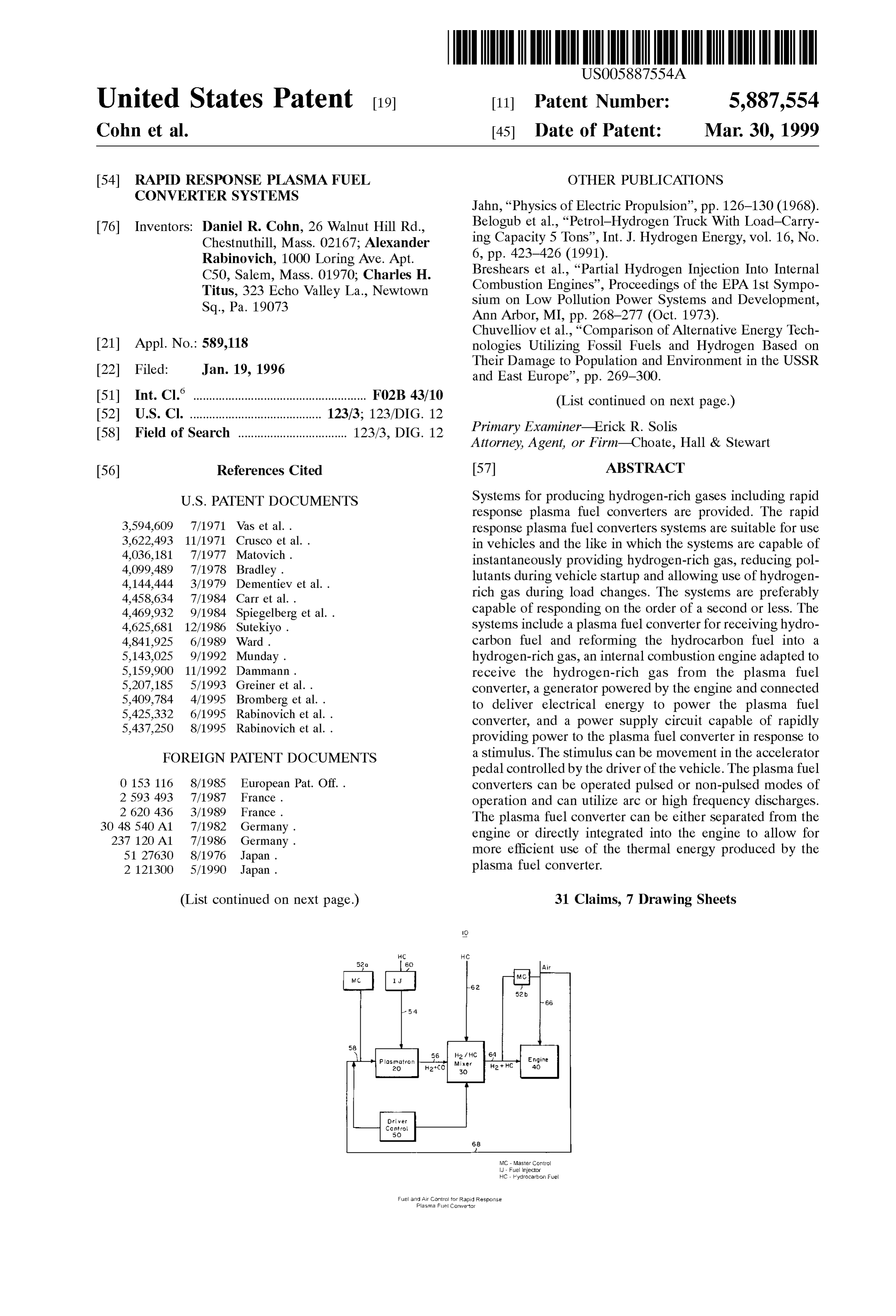
response plasma fuel converters are provided. The rapid 3,594,609 7/1971 Vas et al.. response plasma fuel converters Systems are Suitable for use 3,622,493 11/1971 Crusco et al.. in vehicles and the like in which the Systems are capable of 4,036,181 7/1977 Matovich. instantaneously providing hydrogen-rich gas, reducing pol 4,099.489 7/1978 Bradley. lutants during vehicle Startup and allowing use of hydrogen 4,144,444 3/1979 Dementiev et al.. rich gas during load changes. The Systems are preferably
4,469,932 9/1984 Spiegelberg et al. . capable of responding on the order of a Second or leSS. The 4,625,681 12/1986 Sutekiyo. Systems include a plasma fuel converter for receiving hydro 4,841,925 6/1989 Ward. carbon fuel and reforming the hydrocarbon fuel into a 5,143,025 9/1992 Munday. hydrogen-rich gas, an internal combustion engine adapted to 5,159,900 11/1992 Dammann. receive the hydrogen-rich gas from the plasma fuel 5,207,185 5/1993 Greiner et al.. converter, a generator powered by the engine and connected 5,409,784 4/1995 Bromberg et al. . to deliver electrical energy to power the plasma fuel 5,425,332 6/1995 Rabinovich et al.. converter, and a power Supply circuit capable of rapidly 5,437.250 8/1995 Rabinovich et al.. providing power to the plasma fuel converter in response to FOREIGN PATENT DOCUMENTS a Stimulus. The Stimulus can be movement in the accelerator pedal controlled by the driver of the vehicle. The plasma fuel 0 153 116 8/1985 European Pat. Off.. converters can be operated pulsed or non-pulsed modes of 2593 493 7/1987 France. operation and can utilize arc or high frequency discharges. 2 620 436 3/1989 France. The plasma fuel converter can be either Separated from the 30 48 540 A1 7/1982 Germany. engine or directly integrated into the engine to allow for 237 120 A1 7/1986 Germany. more efficient use of the thermal energy produced by the
2 121300 5/1990 Japan. plasma fuel converter.
(List continued on next page.) 31 Claims, 7 Drawing Sheets
Or wef
Corre
MC-Master Control
J - Fuel Injector
HC - Hydrocarbon Fuel
Fuel and Air Central for Rapid Response
Plasma Fuel Cowetor
Page 2
FOREIGN PATENT DOCUMENTS Jones et al., “Exhaust Gas Reforming of Hydrocarbon Fuels, 1519762 11/1989 U.S.S.R. . Soc. of Automotive Engineers”, Paper 93.1086, pp. 223-234 1 221 317 2/1971 United Kingdom. (1993).
2241 746 9/1991 United Kingdom. Kaske et al., “Hydrogen Production by the Hills Plasma WO 85/OO159 1/1985 WIPO. Reforming Process”, Proc. VI World Hydrogen Energy
OTHER PUBLICATIONS
MacDonald, “Evaluation of Hydrogen-Supplemented Fuel
Correa, “Lean Premixed Combustion For Gas-Turbines: Concept with an Experimental Multi-Cylinder Engine”, Review and Required Research', PD-vol. 33, Fossile Fuel Society of Automotive Engineers, Paper 760101, pp. 1-16 Combustion, ASME, pp. 1-9 (1991). (1976).
Czernichowski et al., “Multi-Electrodes High Pressure Mackay, “Development Of A 24 kW Gas Turbine-Driven Gliding Discharge Reactor and its Applications for Some Generator Set For Hybrid Vehicles', 940510, pp. 99-105, Waste Gas and Vapor Incineration”, Proceedings of Work NoMac Energy Systems, Inc.
shop on Plasma Destruction of Wastes, France, pp. 1-13 Mackay, “Hybrid Vehicle Gas Turbines”, 930044, pp. (1990). 35-41, NoMac Energy Systems, Inc. Das, “Exhaust Emission Characterization of Hydorgen-Op Matthews et al., “Future Analysis of Railplugs as a New erated Engine System: Nature of Pollutants And Their Type of Ignitor”, SAE Paper 922167, pp. 1851–1862 (1992). Control Techniques”, Int. J. Hydrogen Energy, vol. 16, No. Mischenko et al., “Hydrogen ASA Fuel For Road Vehicles”, 11, pp. 765-775 (1991). Proc. VII World Hydrogen Energy Conference, vol. 3, pp. Das, “Hydrogen Engines: A View of the Past and a Look into 2037-2056 (1988).
the Future”, Int. J. of Hydrogen Energy, vol. 15, No. 6, pp. Monroe et al., “Evaluation of a Cu/Zeolite Catalyst to 425–443 (1990). Remove NO from Lean Exhaust”, Society of Automotive Das, “Fuel Induction Techniques for a Hydrogen Operated Engineers, Paper 930737, pp. 195-203 (1993). Engine”, Int. J. of Hydrogen Energy, vol. 15, No. 11 (1990). Rabinovich et al., “On Board Plasmatron Generation of DeLuchi, “Hydrogen Vehicles: An Evaluation of Fuel Stor Hydrogen Rich Gas for Engine Pollution Reduction”, Pro age, Performance, Saftey, Environmental Implants and ceedings of NIST Workshop on Advanced Components for Costs”, Int. J. Hydrogen Energy, vol. 14, No. 2, pp. 81-130 Electric and Hybrid Electric Vehicles, Gaithersburg, MD, (1989). pp. 83-88 (Oct. 1993) (not published). Ducloset al., “Diagnostic Studies of a Pinch Plasma Accel Rabinovich et al., “Plasmatron Internal Combustion Engine erator”, AIAA Journal, vol. 1, No. 11, pp. 2505-2513 (Nov. System for Vehicle Pollution Reduction, Int. J. of Vehicle', 1963). Design, vol. 15, Nos. 3/4/5, pp. 234-242 (1994). Feucht et al., “Hydrogen Drive For Road Vehicles-Results Scott et al., “Hydrogen Fuel Breakthrough With On-De From Fleet Test Run In Berlin', Int. J. Hydrogen Energy, mand Gas Generator', 372 Automotive Engineering, 93, No. vol. 13, No. 4, pp. 243–250 (1988). 8, Warrendal, PA, U.S.A., pp. 81-84 (Aug. 1985). Finegold et al., “Dissociated Methanol AS A Consumable Shabalina et al., “Slag Cleaning by Use of Plasma Heating”, Hydride For Automobiles And Gas Turbines”, pp. pp. 1-7.
1359–1369, Advanceds in Hydrogen Energy 3 (Jun. 13-17, Handbook of Thermodynamic High Temperature Process 1982). Data, pp. 507–547.
Hall et al., “Initial Studies of as New Type of Ignitor: The
Railplug-SAE Paper 912319, pp. 1730–1746 (1991). Varde et al., “Reduction of Soot in Diesel Combustion with Houseman et al., “Hydrogen Engines Based On Liquid Hydrogen and Different H/C Gaseous Fuels”, Hydrogen Fuels, A Review”, G.E., Proc. 3rd World Hydrogen Energy Energy Progess V, pp. 1631-1639. Conf., pp. 949–968 (1980). Wang et al., “Emission Control Cost Effectiveness of Alter Houseman et al., “Two Stage Combustion for Low Emis native-Fuel Vehicles”, Society of Automotive Engineers, sions Without Catalytic Conversters”, Proc. of Automobile Paper 93.1786, pp. 91–122 (1993). Engineering Meeting, Dearborn, MI, pp. 1-9 (Oct. 18-22, Wilson, “Turbine Cars”, Technology Review, pp. 50-56 1976). (Feb./Mar, 1995).
Page 3
Drawing sheet — no readable text.
Page 4
Rectors
IG - High Frequency ignitor for PT PT - PlasmatrOn
WR - Voltage Regulator R - Current Regulator MOSter
C Ontro
Power Control Circuit for Continuous Arc Plasma Fuel Convertor
Page 5
Drawing sheet — no readable text.
Page 6
Pulsed Railgun Plasma Fuel Convertor Pulsed Gliding Discharge Fuel Convertor
2OO s 2OO
SSN N N NZQN N N NSN
NNNNNNN
Pulsed Pinch Plasmatron with
Gliding Radial Discharge
Page 7
Drawing sheet — no readable text.
Page 8
Drawing sheet — no readable text.
Page 9
Drawing sheet — no readable text.
Page 10
RAPID RESPONSE PLASMA FUEL carbon fuel which is Supplied to a plasmatron which reforms CONVERTER SYSTEMS the fuel into a hydrogen-rich gas. Plasmatrons heat an electrically conducting gas either by an arc discharge or by
TECHNICAL FIELD a high frequency inductive or microwave discharge. An The present invention generally relates to Systems includ internal combustion engine is connected to receive the ing rapid response plasma fuel converters for Supplying hydrogen-rich gas from the plasmatron. While these Systems hydrogen-rich gas to internal combustion engines. The are significant improvements over the prior art, it would be invention more particularly relates to Systems including desirable to provide Systems that are capable of rapid rapid response plasmatrons Suitable for use in vehicles and response for instantaneously providing hydrogen-rich gas, the like in which the Systems are capable of instantaneously reducing pollutants during Startup and allowing use of providing hydrogen-rich gas, reducing pollutants during hydrogen-rich gas during typical load changes. The entire vehicle Startup and allowing use of hydrogen-rich gas during contents of both U.S. Pat. Nos. 5,425,332 and 5,437,250 are load changes. incorporated herein by reference. BACKGROUND OF THE INVENTION 15 SUMMARY OF THE INVENTION
Hydrogen is attractive as a fuel or additive for internal It is an object of the present invention to provide Systems combustion engines because hydrogen as a fuel Source can for producing hydrogen-rich gas that utilize plasma fuel Significantly reduce air pollution and can also Serve as an converters capable of rapid response. alternative energy Source to gasoline. See Mishchenko, et It is another object of the invention to provide rapid al., Proc. VII World Hydrogen Energy Conference, Vol. 3 response Systems capable of generating hydrogen-rich gas (1988), Belogub, et al., Int. J. Hydrogen Energy, Vol. 16,423 on the order of a Second or less.
(1991), Varde, et al., Hydrogen Energy Progress V, Vol. 4 It is another object of the invention to provide systems for (1984), Feucht, et al., Int. J. Hydrogen Energy, Vol 13, 243 generating hydrogen-rich gas that reduce vehicle emission (1988), Chuveliov, et al., In: Hydrogen Energy and Power 25 pollutants during Startup or regular operation. Generation, T. Nejat Veziroglu, Ed., Nova Science It is a further object of the invention to provide systems Publisher, New York, N.Y. (1991), Das, Int. J. Hydrogen for generating and utilizing hydrogen-rich gas during load Energy, Vol 16,765 (1991). Moreover, engine efficiency can changes.
be 10-50% higher when running on hydrogen as compared with a gasoline engine. Prior art Systems contemplated either It is another object of the invention to provide systems for Storing hydrogen on-board or generating it on board. generating hydrogen-rich gas in which the power for pro On-board Storage requires high pressure vessels, cryogenic cessing the fuel Source in the plasma fuel converter can be containers if the hydrogen is to be Stored as a compressed rapidly varied according to the flow rate to Satisfy engine gas or liquid, or large getter Volumes and weights if the load requirements.
hydrogen is to be stored as a hydride. Moreover, the refill 35 It is yet another object of the invention to provide rapid time for hydrogen is Substantially longer than that for response Systems for generating hydrogen-rich gas in which gasoline when the hydrogen is to be Stored on-board. the power for processing the fuel in a continuous arc AS to the on-board production of hydrogen, Several plasmatron is varied by optimal variation of both arc plasma approaches have been disclosed in the prior art. For Voltage and current.
example, U.S. Pat. No. 5,143,025 to Munday discloses the 40 It is a further object of the invention to provide rapid use of electrolysis to Separate water into hydrogen and response Systems for producing hydrogen-rich gas which oxygen and introducing the hydrogen into an internal com include a plasmatron capable of pulsed or non-pulsed modes bustion engine. In U.S. Pat. No. 5,159,900 to Dammann, of operation.
hydrogen gas is produced by water interaction with Solid It is a further object of the invention to integrate the carbon. Electrical current is passed between the carbon 45 plasma fuel converter with the engine in order to make more electrodes causing the electrodes to burn and oxidize to form efficient use of the thermal energy of the plasma fuel carbon monoxide and hydrogen. U.S. Pat. No. 5,207,185 to converter produced hydrogen-rich gas.
Greiner et al. discloses a burner which utilizes a portion of These and other objects of the invention are provided by the hydrocarbon fuel to reform another portion to produce rapid response Systems that include a plasma fuel converter hydrogen. The hydrogen is then mixed with the hydrocarbon 50 for receiving hydrocarbon fuel and reforming the hydrocar fuel for introduction into an internal combustion engine. bon fuel into a hydrogen-rich gas, an internal combustion Another System diverts a fraction of the gasoline from the engine connected to receive the hydrogen-rich gas from the flow path to the engine and is passed through a thermal plasma fuel converter, a generator powered by the internal converter and Steam reformed to yield hydrogen-rich gas. combustion engine and connected to deliver electrical See, Breshears, et al., Proc. of EPA 1st Symposium On Low 55 energy to power the plasma fuel converter, and a power Pollution Power Systems Development, 268 (1973). We note Supply circuit capable of rapidly providing power to the that the authors State that this System would not be practical plasma fuel converter in response to a Stimulus. The Systems to generate hydrogen as the Sole fuel for an engine. Yet provided by the present invention can be implemented in another System of this type uses partial oxidation in a vehicles Such that the Stimulus controlling the power Supply catalytic converter to produce hydrogen rich gas. See 60 circuit is a change in the accelerator pedal of the vehicle, Houseman, et al., Proc. 3rd World Hydrogen Energy Conf., which is controlled by the driver of the vehicle. Master 949 (1980). This system requires carefully controlled cata control Systems and fast action valves can be utilized to lytic action and temperature range and has limitations for control the introduction of air and fuel into the plasma fuel Startup and transient response. COnVerter.
U.S. Pat. Nos. 5,425,332 and 5,437,250, both to Rabinov 65 The power Supply circuit includes a transformer con ich et al., disclose plasmatron-internal combustion engine nected to the generator, a battery connected to the generator, Systems. The Systems disclosed include a Source of hydro and an ignition System electrically connected to the battery
Page 11
and capable of initiating arc discharges in the plasma fuel also be significantly reduced. In addition to gasoline, other converter and delivering power to the internal combustion fuel Sources for conversion into hydrogen-rich gas include: engine. The transformer preferably includes a plurality of diesel, oil, heating oil, methanol, ethanol, and natural gas. In Saturable toroidal reactors capable of controlling current order to further reduce pollutants, it is desirable to provide electrically connected thereto and the generator preferably a plasmatron that is capable of rapid response Such that delivers three-phase AC current to the transformer. A recti hydrogen-rich gas can be instantaneously provided, pollut fier is connected to the plasma fuel converter and to the ants during vehicle Startup can be reduced and hydrogen transformer Such that DC current is Supplied to the plasma rich gas can be used during load changes. fuel converter. The Systems also preferably include an In one embodiment of the invention, the plasmatron is ignition system and pulse network (PN). used in a partial oxidation reforming mode rather than as a The foregoing has outlined Some of the more pertinent Steam reformer plasmatron. In the partial oxidation mode, objects of the present invention. These objects should be the plasmatron is employed to provide the optimal tempera construed to be merely illustrative of some of the more ture for a rich mixture of hydrocarbon fuel and air. While prominent features and applications of the invention. Many Steam reforming could be a useful option for Some applications, partial oxidation reformation minimizes elec other beneficial results can be attained by applying the 15 trical disclosed invention in a different manner of modifying the power requirements and can greatly reduce or elimi nate the need for water (in contrast to steam reforming). The invention as will be described. Accordingly, other objects partial oxidation and a fuller understanding of the invention may be had by is exothermic andreaction produces between hydrocarbon fuel and air hydrogen, carbon monoxide and referring to the following Detailed Description of the Pre ferred Embodiments. nitrogen. The reaction in a partial oxidation plasmatron is Set forth in Equation (1) as follows:
BRIEF DESCRIPTION OF THE DRAWINGS
For a fuller understanding of the present invention, ref erence is had to the following description taken in conjunc 25
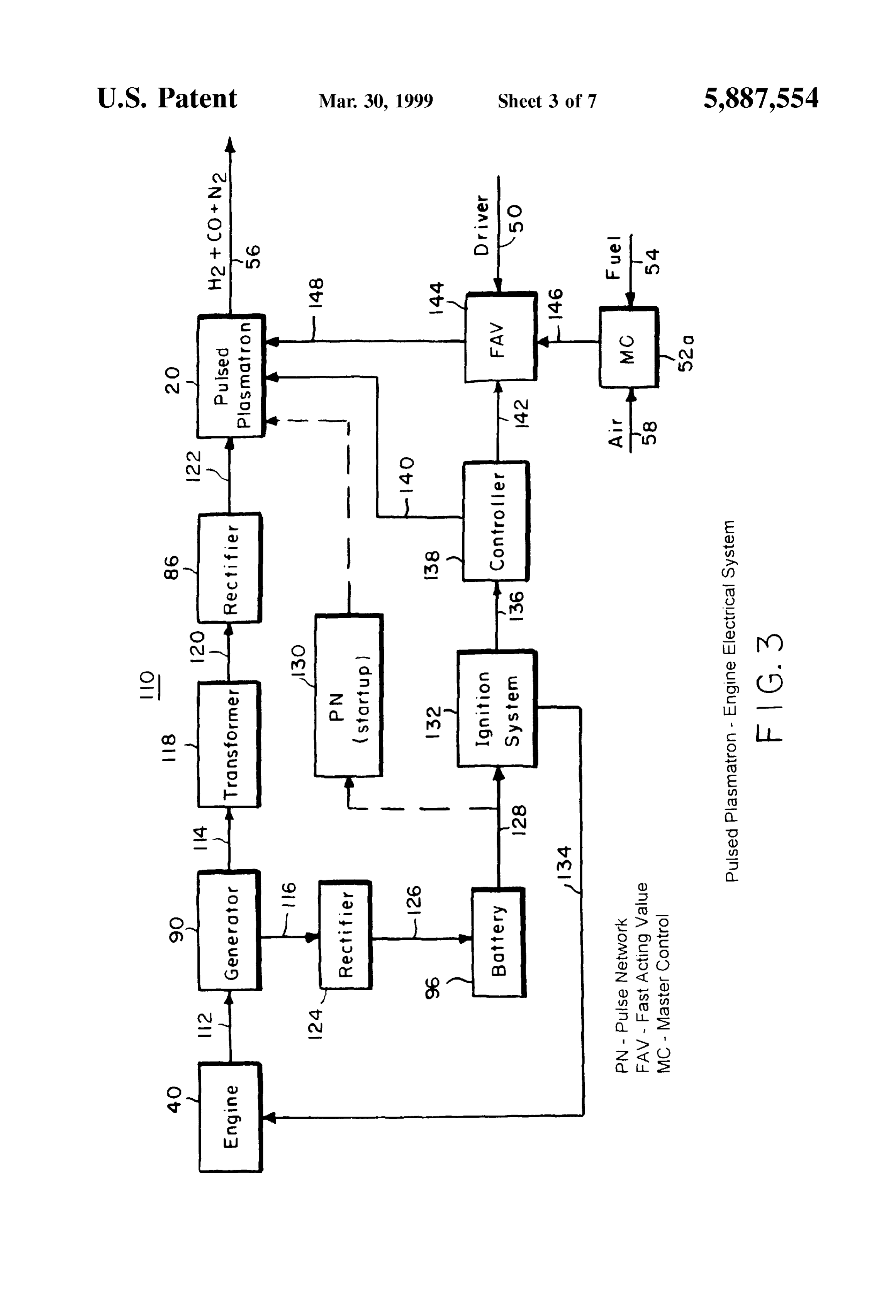
tion with the accompanying drawings, in which: where m and n are the numbers of carbon and hydrogen FIG. 1 is a block diagram illustrating a System for fuel and atoms in a hydrocarbon molecule (e.g., mas8 and ns 15 for air control for a rapid response plasma fuel converter in gasoline). AS used herein, “hydrogen-rich gas” refers to a accordance with the present invention; gas containing hydrogen and carbon monoxide. In Situations FIG. 2 illustrates a power control circuit for a continuous where the partial oxidation reaction of the hydrocarbon fuel arc plasma fuel converter according to the invention; is with air, "hydrogen-rich gas' can also include N. Pro FIG. 3 is a block diagram showing a pulsed plasmatron duction of NO, in the plasma fuel converter is extremely low engine electrical System; because of the highly reducing atmosphere. FIG. 4 is a croSS-Sectional view of a pulsed railgun plasma 35 fuelASconverters
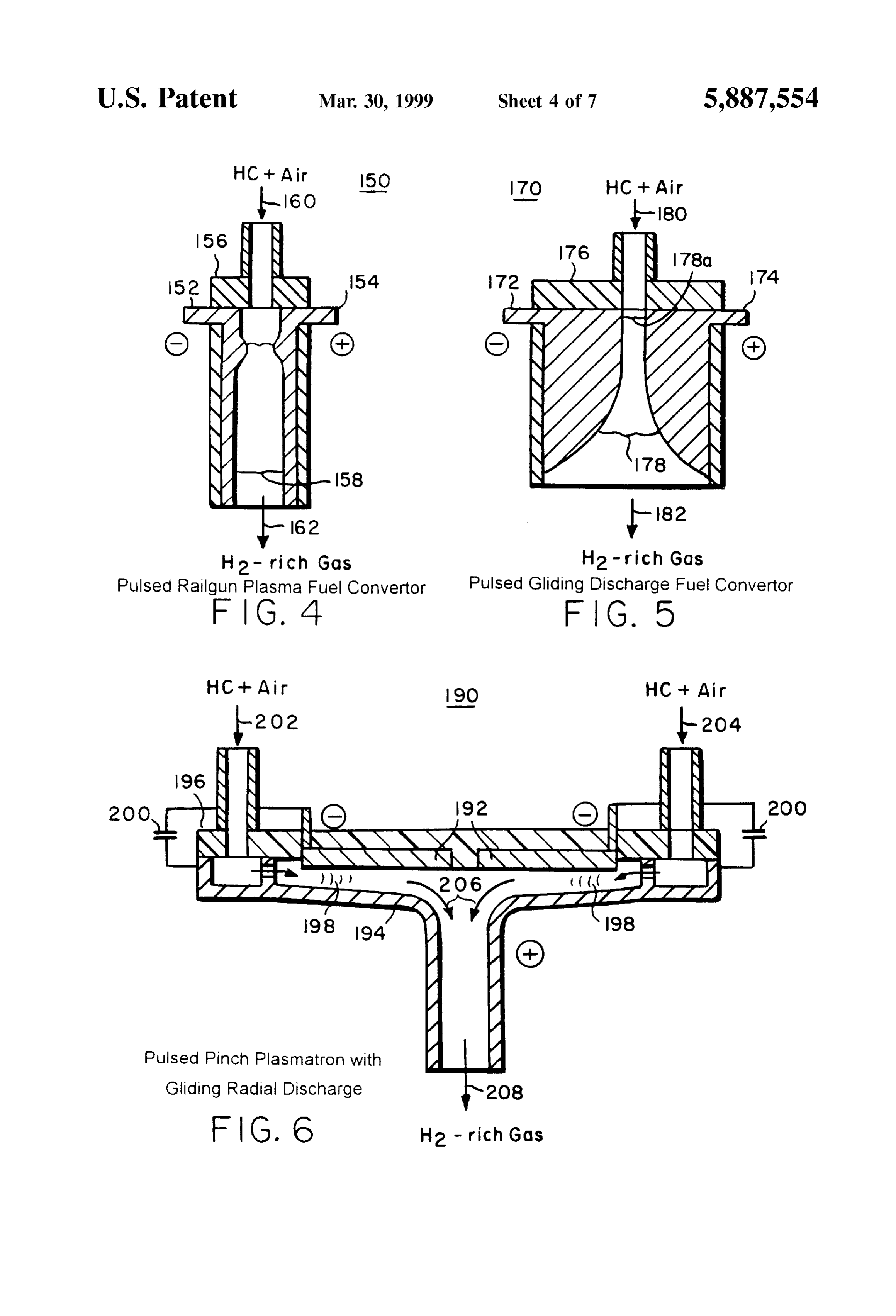
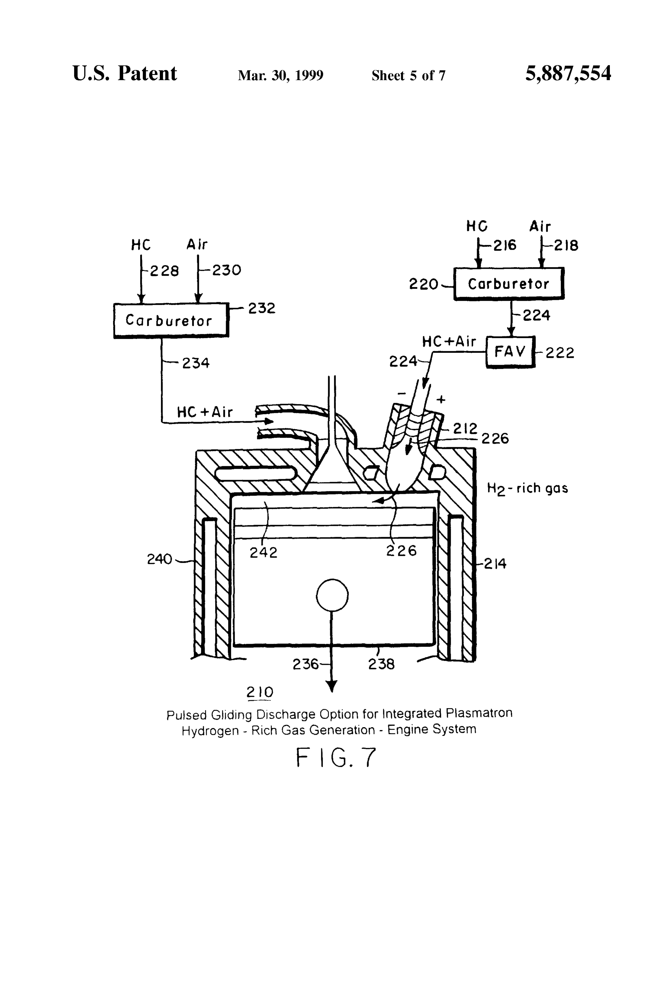
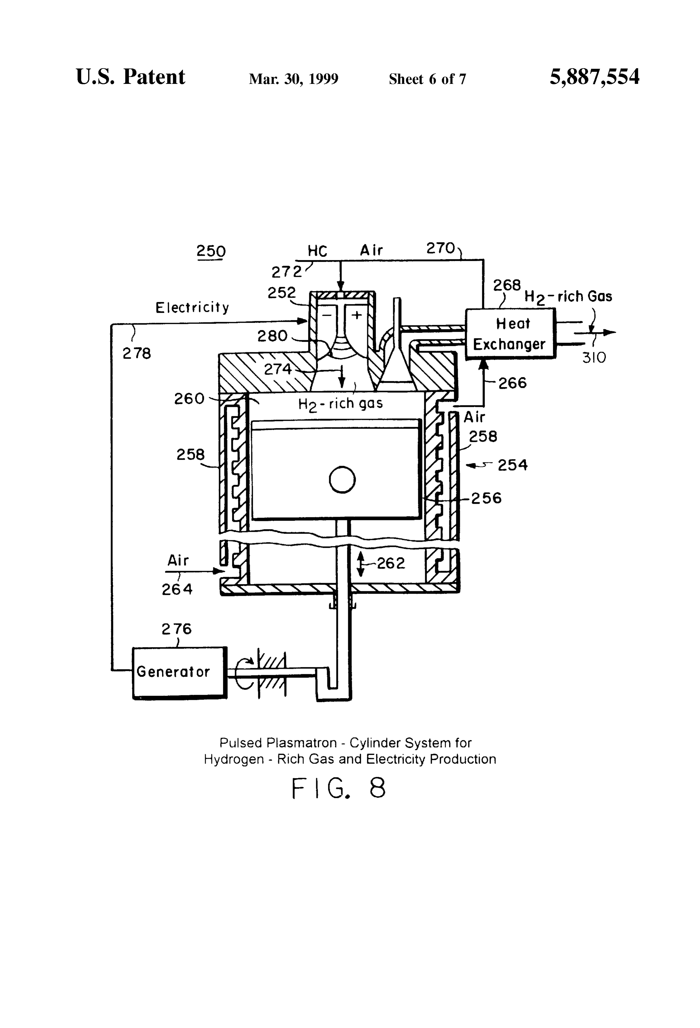
Stated above, it is desirable to develop special plasma capable of rapid response Such that the fuel converter; potential advantages for practical implementation in FIG. 5 is a cross-sectional view of a pulsed gliding vehicles can be fully realized. Rapid response plasma fuel discharge fuel converter; converters are needed to instantaneously provide hydrogen FIG. 6 is a cross-sectional view of a pulsed pinch plas rich gas, reduce engine pollutants during Start-up and to matron with gliding radial discharge, 40 allow for use of hydrogen-rich gas during load changes. AS FIG. 7 is a cross-sectional view of a pulsed gliding used herein, "rapid response' refers to plasma fuel convert discharge for an integrated plasmatron hydrogen-rich gas erS capable of responding and generating hydrogen-rich gas generation-engine System according to an embodiment of on the order of a Second or leSS. The present invention also the present invention; provides rapid response plasma fuel converters that are FIG. 8 is a cross-sectional view of a pulsed plasmatron 45 capable of either Steady State or pulsed modes of operation cylinder System for the production of hydrogen-rich gas and for the plasma fuel converters.
electricity; and Referring now to FIG. 1, a system 10 for fuel and air control
FIG. 9 is a block diagram illustrating a hybrid plasma fuel dance with for a rapid response plasma fuel converter in accor the present invention is shown. The plasma fuel converter-catalytic partial oxidation reformer for use in the 50 converter could present invention. be an AC or arc DC plasmatron or a high frequency plasmatron using inductive or microwave heating.
Similar reference characters refer to Similar parts through The plasma fuel converter could be operated in either a out the Several views of the drawings. continuous or pulsed mode of operation. System 10 includes DETAILED DESCRIPTION OF THE plasmatron 20, engine 40, and H/hydrocarbon fuel mixer 30 55 which can provide variable mixtures 64 of hydrogen-rich
PREFERRED EMBODIMENTS
gas and hydrocarbon fuel. System 10 also includes fuel
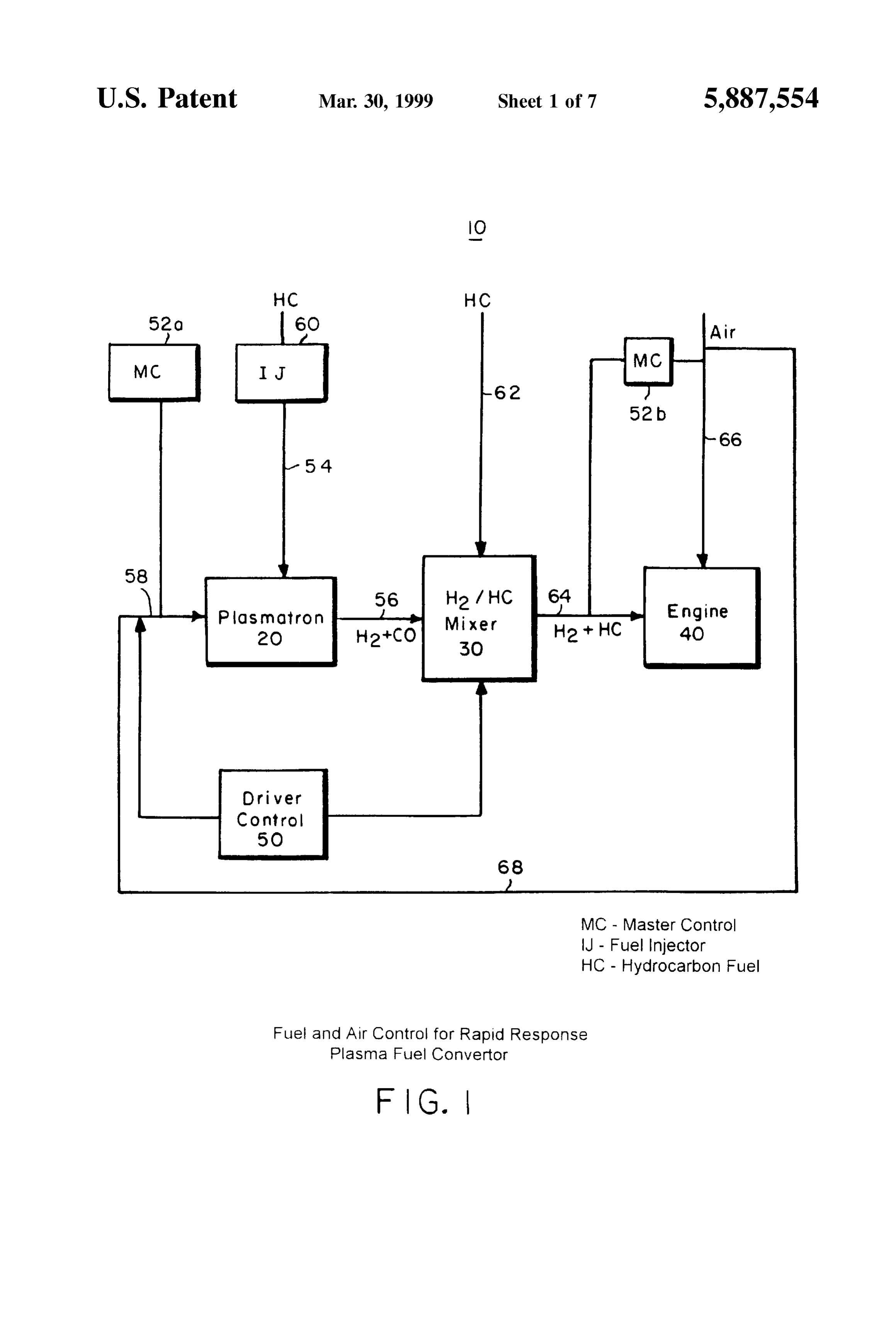
As discussed in U.S. Pat. Nos. 5,425,332 and 5,437,250, pump and injector 60 and master automatic control units 52a plasma devices can provide an effective means for onboard and 52b which maintain the desired mixture of air and fuel conversion of gasoline and other fuels into hydrogen-rich in the plasma fuel converter and in the engine. Air Sources gas (hydrogen and carbon monoxide) for use in vehicular 60 58 and 68 and hydrocarbon sources 54 and 62 are provided internal combustion engines and for other applications. Use to system 10 as shown in FIG. 1.
of hydrogen-rich gas in mixtures with gasoline produces a In order for the plasmatron to rapidly respond, liquid fuels faster flame front which makes it possible to greatly reduce must be introduced into the plasma fuel converter rapidly the amount of fuel in the cylinder charge. In Such lean and in a highly controlled manner. This can be accomplished operation the charge temperature is significantly reduced, 65 utilizing fuel pump and fuel injector 60 as shown in FIG. 1. thereby greatly decreasing the production of nitrogen oxides Air 66 and 68 can be introduced into system 10 using a (NO). Carbon monoxide and hydrocarbon emissions can compressor (not shown in FIG. 1). The rate of air introduc
Page 12
S 6 tion is determined by the engine power requirement. A In certain situations, it may be desirable to utilize rapid portion of air flow 68 is fed to plasmatron as air flow 58. The power control in conjunction with pulsed plasmatrongen air flow 58 is determined by the accelerator pedal controlled eration of hydrogen-rich gas. Pulsed plasmatron operation by the driver 50. The amount of fuel 54 introduced by the would be optimized for the required power gas flow by fuel injector 60 is controlled by the air flow 58 using master changing the repetition rate of pulses at the same power per control 52a. The ratio of fuel to air introduced into plasma pulse of the plasmatron.
tron 20 is preferably designed to be very rich, i.e. it will be The pulsed plasmatron-internal combustion engine Sys close to the Stoichiometric ratio in Equation (1). Hydrogen tem could operate with a unique circuit to allow variation of rich gas 56 containing hydrogen, carbon monoxide and repetition rate in accordance with engine power demand. nitrogen are thus produced in plasmatron 20. This circuit is designed to be compatible with a vehicular For high engine loads, it may be desirable to provide electrical System. An exemplary pulsed plasmatron-engine hydrogen-rich gas to engine 40 by a Small storage tank (not electrical System Suitable for use in the present invention is shown in FIG. 1) in addition to providing the gas directly illustrated in FIG. 3.
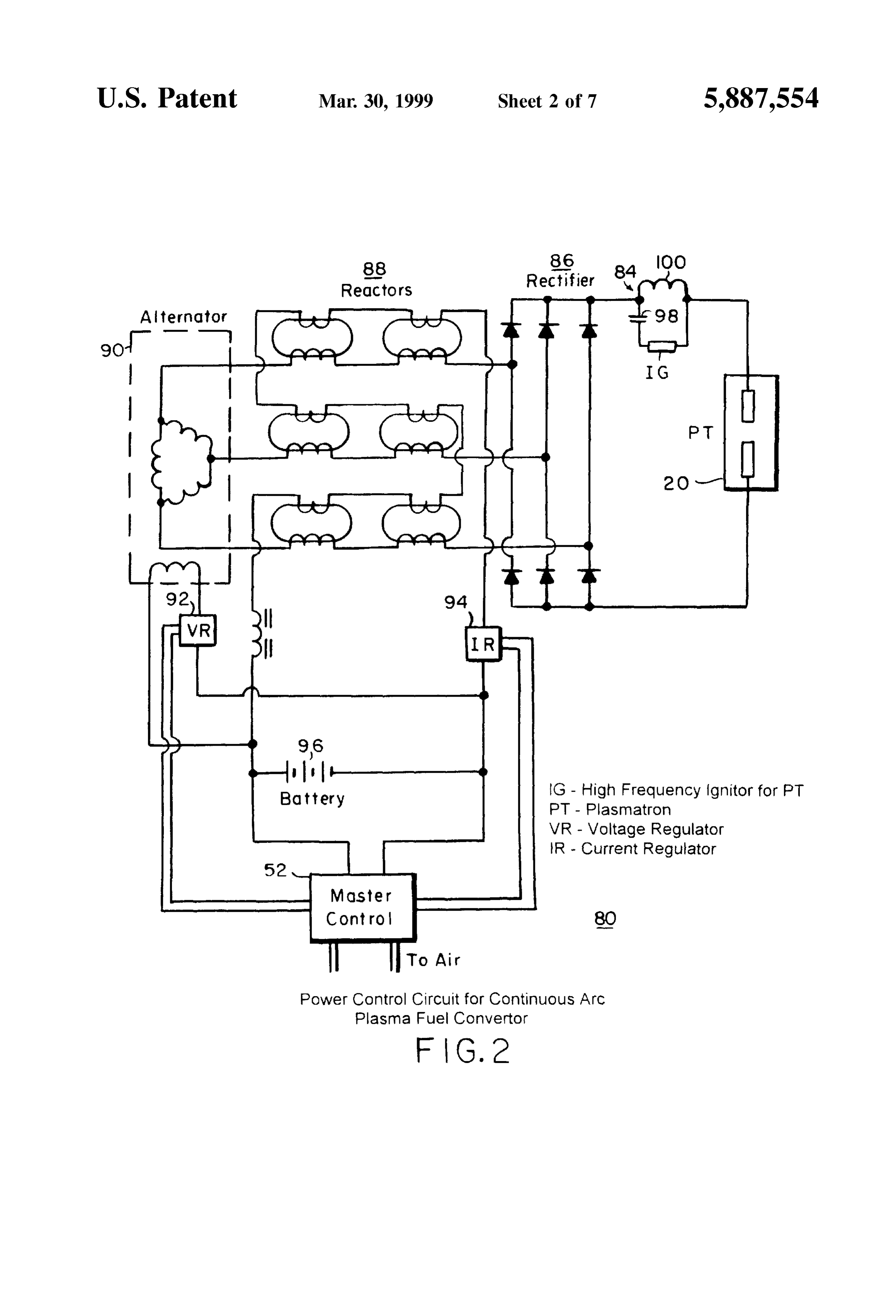
from the plasma fuel converter. In Some situations, where System 110 includes engine 40 that produces mechanical the highest engine power levels are required, it may be desirable to utilize 100% gasoline operation (fuel 62) with 15 energy 112 to power generator 90. The generator 90 delivers stoichiometric fuel to air mixtures for brief periods of three phase AC current to transformer 118 and charges acceleration; this mode of operation increases cylinder Volu battery 96 by electrical energy through circuits 114 and 116. metric power efficiency and reduces plasma fuel converter Transformer 118 increases the AC voltage which is supplied electrical power requirements for a given amount of engine to the rectifier 86. Rectifier 86 in turn supplies DC power power. This mode of operation would likely be used only for 122 to the arc of the pulsed plasmatron 20. As mentioned conditions of highest power level. As further shown in FIG. above, the generator 90 also is capable of providing elec 1, hydrogen-rich gas flow 56 can be combined with hydro trical energy 126 to charge the battery 96 using rectifier 124. carbon fuel source 62 in different ratios by using mixer 30. The battery 96 can be used to supply energy 128 to the spark Plow 64 of hydrogen-rich gas, hydrocarbon fuel or combi ignition system 132 and for the pulse network (PN) 130 for nations thereof is controlled by master control 52b, which is 25 initial startup of the plasmatron 20. determined by air flow 66 and engine load requirements. The During engine operation, DC power will be always con driver could manually change the ratio between the nected to the pulsed plasmatron 20. As further shown in FIG. hydrogen-rich gas and gasoline depending on driving con 3, the high Voltage and high frequency Spark ignition System ditions. 132 delivers power 136 to controller 138 to ignite discharge FIG. 2 illustrates a rapid power control circuit 80 for a 140 in the plasmatron 20. Controller 138 simultaneously continuous arc plasmatron according to the present inven will open the Solenoid valve in the fast acting valve (FAV) tion. The power for processing the fuel in the plasma fuel 144 via 142 to send a portion of the air 58 and fuel 54 to converter must be capable of being rapidly varied according plasmatron 20 via 148. Air 58 and fuel 54 are fed to to the flow rate to meet engine load requirements. In a plasmatron 20 as a mixture 146 that is controlled by master continuous arc plasmatron, the power is changed by optimal 35 control 52a. The fuel injection System already existing in the variation of both arc plasma Voltage and current. The circuit vehicle could be used as a FAV. AS discussed above in shown in FIG. 2 allows for the control of current and connection with FIG. 1, the rate of air introduction 58 is Voltage. determined by the engine power requirement and the amount The arc plasma in plasmatron 20 is operated with DC of fuel 54 is determined by the air flow 58. The engine power current in order to facilitate Stable operation and allow for 40 requirement for air flow 58 is determined by the accelerator Substantial variation in arc length and Voltage. If current is pedal controlled by the driver in the vehicle 50 and master maintained at a constant level and gas flowrate is increased, control 52a is connected to the accelerator pedal. The width the arc resistivity and Voltage increases, thereby adding of the pulse of Such a system is about 1.5-10 ms. The power without increasing current and consequently reducing plasmatron will produce a pulse of plasma gas 56 which will electrode erosion. AC current is used in the first part of the 45 be delivered to the engine 40. Alternatively, hydrogen-rich circuit to allow for rapid adjustment of current. The diode gas can be introduced into a storage tank for later use in the circuit in FIG. 2 changes the current from AC to DC for engine. In either embodiment, hydrogen-rich gas 56 can be operation of the arc plasma. combined with other fuel (such as hydrocarbon fuel 62 AS the demand for more power occurs, both Voltage and shown in FIG. 1).
current will increase. The Voltage and current control is used 50 During initial Start-up, the plasmatron will be started to provide the required amount of power. Current control is utilizing electrical energy 128 from the battery 96 supplied achieved by the use of Saturable toroidal reactors 88, which to the PN 130 and ignition system 132. The PN is a is possible with AC current input to the diode rectifier. combination of Several Stages of capacitors and inductors. The controlled DC power for the plasmatron may also be Several types of pulsed plasma fuel converters and Sys obtained by a controlled rectifier System in place of the 55 tems arrangements for use in accordance with the present Saturable reactor-diode rectifier System. invention will now be discussed. These plasma fuel con Circuit 80 also includes a high voltage ignitor circuit 84 verters and System arrangements are exemplary and are not to Start the arc plasma discharge. The circuit utilizes a to be construed as limiting. Three types of plasma fuel capacitor 98 and inductor 100 to provide a voltage of about converters that do not require water cooling are illustrated in 20 kilovolts to ignite a DC arc in the plasmatron. 60 FIGS. 4-6. The plasma fuel converters will provide uniform The Voltage/current ratio may be varied for performance discharge with high average power. The advantages of the optimization. This can be accomplished with Voltage regu uniform pulsed plasma fuel converters include high plasma lator 92, current regulator 94, both of which are connected fuel converter thermal efficiency (no water cooling) and long to battery 96 and master control 52. As discussed herein, lifetime because of shorter contact time of the electrodes alternator 90, which is also connected to master control 52, 65 with the plasma arc roots. The plasma fuel converters shown provides three phase AC current to the transformer and in FIGS. 4-5 have been developed previously for other charges battery 96. applications. See, Hall et al., Initial Studies of a New Type
Page 13
of Ignitor. The Railplug, SAE Paper 912319 (1991); Czer producing hydrogen-rich gas 208. AS a result, the lifetime of nichowski et al., Multi-Electrodes High Pressure Gliding the electrodes would be very high and the material would not Discharge Reactor and Its Applications for Some Waste Gas be limited to thermoconductive copper. and Vapor Incineration, Proceedings of Workshop on The rate of conversion of the hydrocarbon fuel would be Plasma Destruction of Wastes, France (1990). However, higher because of the increased residence time. The radial these plasma fuel converters have not been used for gliding discharge plasmatron will be modified from the hydrogen-rich gas generation in a vehicle. Nor have Such previous designs by using pulsed fuel and air injection plasma fuel converters been utilized in Systems capable of coordinated with pulsed power as discussed previously in rapid response. Each of these types of plasma fuel converters connection with FIGS. 1-3 such that the plasmatron is must accordingly be modified for use in the present inven capable of rapidly responding to engine load requirements tion. and instantaneously providing hydrogen-rich gas. In a rail-gun type of a plasma fuel converter 150 as shown In another embodiment of the invention, the pulsed plas in FIG. 4, a cathode 152 is electrically insulated from the matron for hydrogen-rich gas production could be integrated anode 154 by insulator 156. A mixture of hydrocarbon fuel with the cylinders of an engine. In this way, the energy and air 160 is introduced into plasma fuel converter 150 as 15 released by the partial Oxidation can be used in the engine. further illustrated in FIG. 4. Alternatively, hydrocarbon fuel An exemplary pulsed gliding discharge option for an inte and air can be introduced Separately and combined in the grated plasmatron hydrogen-rich gas production-engine Sys plasma fuel converter. The plasma arc 158 Sweeps axially tem is illustrated in FIG. 7. System 210 includes plasmatron between the two parallel electrodes 152 and 154 and 212 connected to engine 214. The operation of the integrated reformed hydrogen-rich gas 162 exits the plasma fuel con System is similar to a plasma-jet ignition engine. A main verter. The acceleration is mainly provided by the interaction carburetor and intake manifold 232 controls the quantities of of the arc current with the Self-magnetic field and by gas hydrocarbon fuel 228 and air 230 such that the desired flow. The rail-gun plasma fuel converter will be modified to hydrocarbon fuel-air mixture 234 fed to the combustion operate at an order of magnitude larger size than previous chamber 242 of engine 214 is properly proportioned. A designs (Hall et al., Initial Studies of a New Type of Ignitor: 25 separate carburetor and intake manifold 220 feeds a fuel-rich The Railplug, SAE Paper 912319 (1991)) and to provide mixture of fuel and air 224 into plasmatron 212 using a fast conversion of hydrocarbon fuel. The rail-gun plasma fuel acting valve (FAV) 222. Carburetor 220 controls the quan converter further will be modified from the previous designs tities of hydrocarbon fuel 216 and air 218 such that hydro by using pulsed fuel and air injection coordinated with carbon fuel-air mixture 224 introduced into plasmatron 212 pulsed power as discussed previously in connection with via fast action valve 222 is properly proportioned. FIGS. 1-3 such that the plasma fuel converter is capable of After the lean mixture 234 is compressed in combustion rapidly responding to engine load requirements and instan chamber 242, the Solenoid controlled FAV 222 sends a taneously providing hydrogen-rich gas. portion of the rich fuel-air mixture 224 into the plasmatron Referring now to FIG. 5, a gliding discharge plasma fuel 212. Plasmatron 212 produces and injects a jet of hydrogen converter is shown. Plasma fuel converter 170 includes 35 rich gases 226 into the combustion chamber 242, igniting the cathode 172 electrically insulated from anode 174 by insu lean charge of mixture 234. The combustion process pro lator 176. A mixture of hydrocarbon fuel and air 180 is duces mechanical energy 236 by the piston 238 reciprocat introduced into plasma fuel converter 170. In an alternative ing in engine cylinder 240. For this configuration, the pulsed embodiment, hydrocarbon fuel and air can be introduced plasmatron must operate at gas densities that are signifi Separately and combined in the plasma fuel converter. The 40 cantly higher than atmospheric density. The Studies of the arc discharges 178 are initiated at the spot where the distance railplug ignitor (Hall et al., Initial Studies of a New Type of between the diverging electrodes is the shortest (e.g., 178a) Ignitor. The Railplug, SAE Paper 912319 (1991)) have and progressively spread along the electrodes in the direc shown that railplugs can produce a high Velocity jet at a tion of the reagent's flow until they disappear by themselves preSSure of 200 psig.
after a certain path (Czernichowski et al., Multi-Electrodes 45 In yet another embodiment of the invention, a pulsed High Pressure Gliding Discharge Reactor and Its Applica plasmatron for hydrogen-rich gas production could be incor tions for Some Waste Gas and Vapor Incineration, Proceed porated into the cylinder of an engine to provide a Self ings of Workshop on Plasma Destruction of Wastes, France sustaining system such as that shown in FIG. 8. This one (1990)). This path is defmed by the geometry of the cylinder engine would be operated with a very rich mixture electrodes, by the conditions of flow, and by the character 50 of hydrocarbon fuel and air and consequently would produce istics of the power Supplies. The gliding discharge plasma very little NO. During the partial oxidation reaction, about fuel converter will be modified from the previous designs by 17 percent of the low heating value of gasoline is released using pulsed fuel and air injection coordinated with pulsed to the hydrogen-rich gas. In Some situations, it is desirable power as discussed previously in connection with FIGS. 1-3 to transform at least part of this heat energy to the mechani Such that the plasma fuel converter is capable of rapidly 55 cal energy of the piston motion and Subsequently to the responding to engine load requirements and instantaneously electrical energy Supplied to the plasmatron. Another part of providing hydrogen-rich gas. heat energy could be recovered by air incoming to the The radial gliding pulsed plasmatron shown in FIG. 6 is plasmatron. The air will take energy during regenerative a modification of a gliding discharge plasmatron Such as that cooling of the cylinder walls and then in the hydrogen-rich shown in FIG. 5. Plasmatron 190 includes a plurality of 60 gas exhaust heat eXchanger. In this manner, the energy of the cathodes 192 electrically insulated from anode 194 by partial oxidation reaction can be utilized in the System. insulator 196. Mixtures of hydrocarbon fuel and air 202,204 The system 250 illustrated in FIG. 8 includes plasmatron are introduced into plasmatron 190 as shown in FIG. 6. 252 and engine 254. Engine 254 includes cylinder wall 258 Discharges 198 will be simultaneously ignited between the and piston 256. A generator 276 is connected to the shaft of anode 194 and several radial cathodes 192 at the shortest 65 piston 256.
distance and will glide toward the center in the direction of Hydrocarbon fuel 272 is mixed with air 270 and is arrows 206 under the influence of the gas flow, thereby introduced into plasmatron 252. Alternatively, hydrocarbon
Page 14
fuel and air can be introduced into the plasmatron Separately and flow control valve 304 control the quantity of air 298 and combined within the plasmatron. The plasmatron illus while master control 302 and flow control valve 306 control trated in FIG. 8 is a gliding discharge plasmatron and thus the quantity of hydrocarbon fuel 300 introduced into plasma arc discharges 280 are initiated at the location where the fuel converter 292. Hydrogen-rich gas 308 exits plasma fuel distance between the diverging electrode is the Shortest. It converter 292 and is fed to catalytic reformer 296 and/or will be appreciated by those skilled in the art that other engine 294. Flow to a catalytic reformer 296 and engine 294 plasmatrons can be utilized in the system shown in FIG. 8 istively. regulated by flow control valves 310 and 312, respec and that Such modifications are within the Scope of the Master control 318 and flow control valve 320 regulate present invention. Hydrogen-rich gas 274 exits plasmatron 252 and is fed to the combustion chamber 260 of engine 254. the flow of air 314 to catalytic reformer 296 while master A portion of the heat energy released reciprocates piston 256 control 318 and flow control valve 322 regulate the flow of hydrocarbon fuel 316 to catalytic reformer 296. Reformed in the directions of arrow 262. Mechanical energy produced by engine 254 powers generator 276, thereby producing gases 324 are fed to engine 294. As further shown in FIG. 9, reformed gases 324 can be combined with hydrogen-rich electricity 278. At least a portion of electricity 278 can be gases 308 prior to introduction in engine 294 in a predeter utilized to power plasmatron 252, thereby producing a 15 mined manner utilizing flow control valve 312. The flow of Self-Sustaining System. gases 308 and/or 324 entering engine 294 is determined by Another part of heat energy could be recovered by air 270 the quantity of air 328 required for engine requirements and incoming to the plasmatron 252. Air 264 will take energy is controlled by master control 326.
during regenerative cooling of the cylinder walls 258 of the During Startup, hot hydrogen-rich gas and possibly radia engine 254 and then as air 266 in the hydrogen-rich gas 274 tion from the plasma fuel converter would pass through the exhaust heat eXchanger 268. In order to prevent the leaking catalytic reformer, thereby providing Sufficient heat to a of hydrogen-rich gas to the atmosphere, the entire temperature where the catalytic reformer can effectively plasmatron-engine unit could be enclosed in a completely reform fuel. After the catalytic reformer is warmed up, the sealed shield (not shown in FIG. 8). Such a shield could be control System could Switch fuel and air to it and the plasma formed of ceramic or the like. AS discussed herein, a portion 25 fuel converter and catalytic converter System could run in of the incoming air could be injected through the Seal in Series or in parallel.
order to create positive preSSure and prevent leaking. It will As discussed in U.S. Pat. Nos. 5,425,332 and 5,437,250, be appreciated by those skilled in the art that the System the major contributor to air pollution in the U.S. is the illustrated in FIG. 8 can readily be modified for other fossil-fuel powered motor vehicle. In 1987, 66 percent of the alternatives within the Scope of the invention. For example and 20 percent ofemission, carbon monoxide 43 percent of NO, emissions, and while not intending to be limiting, one variation can vehicles alone. The particle rapid emissions came from motor response and pulsed operation include the use of two or more cylinder units employed capabilities of the plasma fuel converter and Systems pro together.
In still another embodiment of the invention, it may be Vided by the present invention could significantly aid in the advantageous to use a conventional catalytic or thermal 35 improvement of air quality.
reformer in conjunction with the plasma fuel converter. The SpecificIt should be appreciated by those skilled in the art that the use of a catalytic reformer could further increase fuel lized as aembodiments disclosed above may readily be uti efficiency. Houseman et al., Hydrogen Engines Based On Structures for carrying out theorsame basis for modifying designing other methods or purpose of the present
Liquid Fuels: A Review, Proceedings. Third World Hydrogen
Energy Conference, p. 949 (1980). The plasma fuel con 40 art that Such equivalent constructions do those invention. It should also be realized by skilled in the not depart from the verter could be used to provide immediate production of Spirit hydrogen-rich gas and to warm up the conventional claims.and Scope of the invention as Set forth in the appended reformer. The conventional reformer could then be employed to produce hydrogen-rich gas with greater effi What is claimed is:
ciency than the plasma fuel converter Since it does not 45 1. A power System comprising: require external power. The plasma reformer could then a plasma fuel converter for receiving hydrocarbon fuel operate in parallel with the catalytic reformer to provide fast and reforming the hydrocarbon fuel into a hydrogen response and extra levels of hydrogen-rich gas for the rich gas, engine. an internal combustion engine adapted to receive the In parallel operation, the conventional reformer prefer 50 hydrogen-rich gas from the plasma fuel converter, the ably would be sized so that it only needs to provide engine operating at a load condition; hydrogen-rich gas at moderate flow level (e.g., on the order a generator powered by the engine and connected to of twice the idle level). Because conventional reformer size deliver electrical energy to power the plasma fuel and cost are significant factors, the resulting reduction of the converter, and conventional reformer size by a factor of five or more could 55 a power Supply circuit configured to provide power with be significant. Additionally, because operation of the con a controlled Voltage/current ratio to the plasma fuel ventional reformer is less of a power drain than the plasma converter in response to a change in the load condition. device, it would be utilized where possible. 2. The power System of claim 1, wherein the System is The plasma fuel converter and conventional reformer configured to respond in about one Second or leSS. arrangement could also be employed and used in Series, e.g., 60 3. The power system of claim 1, wherein the plasma fuel the conventional reformer could be warmed by hot gas and converter utilizes an arc discharge or a high frequency radiation from the plasma fuel converter and could provide discharge.
additional processing of the gas from the plasma device. 4. The power system of claim 3, wherein the high fre FIG. 9 schematically shows an illustrative configuration quency discharge is provided by inductive or microwave for a hybrid plasma fuel converter-conventional reformer 65 heating.
device. System 290 includes plasma fuel converter 292, 5. The power system of claim 1, wherein the plasma fuel engine 294 and catalytic reformer 296. Master control 302 converter is an arc plasmatron.
Page 15
6. The power system of claim 5, wherein the power supply 18. The power system of claim 13, wherein the plasma circuit comprises: tron is a pulsed railgun plasmatron. a transformer connected to the generator; 19. The power system of claim 13, wherein the plasma a battery electrically connected to the generator; and tron is a pulsed gliding discharge fuel plasmatron. 20. The power system of claim 1, wherein the plasma fuel an ignition System electrically connected to the battery converter is a pulsed pinch plasmatron with gliding radial and configured to initiate discharges in the plasmatron. discharge.
7. The power system of claim 6, further including a 21. The power system of claim 1 wherein the plasma fuel plurality of Saturable toroidal reactors connected to the converter is integrated with the internal combustion engine. transformer and configured to control current. 1O 22. The power System of claim 21, wherein the plasma 8. The power system of claim 7, further including a fuel converter is a pulsed gliding discharge fuel plasmatron. rectifier electrically connected to plurality of Saturable tor 23. The power system of claim 22, further including a heat oidal reactors and to the plasmatron. eXchanger configured to preheat incoming air to the plas 9. The power system of claim 8, wherein the generator is matrOn.
configured to deliver three-phase AC current to the trans 15 24. The power system of claim 21, wherein the power former and the rectifier is configured to Supply DC current Supply circuit comprises:
to the plasmatron. a transformer connected to the generator; 10. The power system of claim 6, further including a a battery electrically connected to the generator; and controller and a fuel injector configured to maintain a an ignition System electrically connected to the battery predetermined mixture of the hydrocarbon fuel and the air and configured to initiate discharges in the plasma fuel introduced into the plasmatron in response to the change in COnVerter.
the load condition. 25. The power system of claim 21, further including a first 11. The power system of claim 1, further including a carburetor for controllably introducing a fuel and air into the controller and a fuel injector configured to maintain a combustion chamber of the internal combustion engine. predetermined mixture of the hydrocarbon fuel and the air 25 26. The power system of claim 25, further including a introduced into the plasmatron in response to the change in Second carburetor for controllably introducing the hydrocar the load condition. bon fuel and air into the plasma fuel converter. 12. The power system of claim 1, wherein the system is 27. The power system of claim 26, further including a fast used in a vehicle and the change in the load condition is action valve positioned between the Second carburetor and movement in an accelerator pedal in the vehicle. the plasma fuel converter.
13. The power system of claim 1, wherein the plasma fuel 28. The power system of claim 21, wherein the plasma converter is a partial oxidation plasmatron. fuel converter is integrated with the internal combustion 14. The power system of claim 13, further including a engine Such that thermal energy in the hydrogen-rich gas can controller and a fuel injector configured to maintain a be used in the internal combustion engine. predetermined mixture of the hydrocarbon fuel and the air 35 29. The power system of claim 28, further including at introduced into the plasmatron in response to the change in least one heat eXchanger configured to preheat incoming air the load condition. to the plasma fuel converter.
15. The power system of claim 14, wherein the predeter 30. The power system of claim 21, further including a heat mined mixture of the hydrocarbon fuel and the air intro eXchanger configured to preheat incoming air to the plasma duced into the plasmatron is about equal to a Stoichiometric 40 fuel converter.
ratio of fuel to air. 31. The power system of claim 21, further including a 16. The power system of claim 13, wherein the system is catalytic or thermal fuel reformer connected to the plasma configured for a pulsed mode of operation. fuel converter and the internal combustion engine. 17. The power system of claim 13, wherein the system is configured for pulsed and non-pulsed modes of operation. k k k k k
Provenance
- Collection
- Cited prior art
- Original PDF
- patentimages.storage.googleapis.com →
- Filed
- 1996-01-19
- Pages
- 15
- Method
- pdftotext (the PDF's own text layer) + pdftoppm 300dpi page scans
- Source
- Google Patents bibliographic record
- Granted
- 1999-03-30
- Inventors
- Daniel R. Cohn; Alexander Rabinovich; Charles H. Titus
- Transcribed from
- patentimages.storage.googleapis.com →