patent · US4625681
Method of obtaining mechanical energy utilizing H2 O plasma generated in multiple steps
2 December 1986
Page 1 — bibliographic record
United States Patent (19) 11) Patent Number: 4,625,681 Sutekiyo (45) Date of Patent: Dec. 2, 1986 54 METHOD OF OBTAINING MECHANICAL (57) ABSTRACT ENERGY UTILIZING H2O PLASMA A method of obtaining mechanical energy utilizing GENERATED IN MULTIPLE STEPS H2O-plasma that is generated in multiple steps. The 75) Inventor: Uozumi Sutekiyo, Hachiogi, Japan general field of art of the invention is that of producing (73) Assignee: Sutabiraiza Company, Limited, a reactive thrust by using plasma. The mechanical en Saitama, Japan ergy provided by the invention is produced by explo sion of electrically conductive plasma which is gener (21) Appl. No.: 699,404 ated by dissociating H2O. At the first step H2O (gas) produced by a gasifier is reduced to a plasmatic state by 22 Filed: Feb. 7, 1985 electrical discharge. At the second step the plasmatic (30) Foreign Application Priority Data gas is treated by a further and stronger electrical dis Feb. 10, 1984 JP Japan .................................. 59.21987 charge and by high-frequency induction heating, and the energy level of the plasma is raised to a point at 51) Int. Cl. .............................................. FO2B 43/08 which a plasma jet is ready to be produced. At the third 52 U.S. C. ................................ 123/3; 123/DIG. 12 step, the plasma jet is generated by periodically modu 58) Field of Search ..... ... 123/3, DIG. 12, 536, lating the high voltage for the second electrical dis 123/537 charge, and a high-pressure thermal explosion reaction
is caused by synchronizing the generation with com pression of the plasma jet. The result is that energy
4,297,983 11/1981 Ward ................................... 123/536 ultra-high temperature is converted to mechanical en ergy.
Primary Examiner-E. Rollins Cross
Attorney, Agent, or Firm-Spencer & Frank 6 Claims, 7 Drawing Figures
Page 2
Drawing sheet — no readable text.
Page 3
Drawing sheet — no readable text.
Page 4
Drawing sheet — no readable text.
Page 5
Drawing sheet — no readable text.
Page 6
Drawing sheet — no readable text.
Page 7
Drawing sheet — no readable text.
Page 8
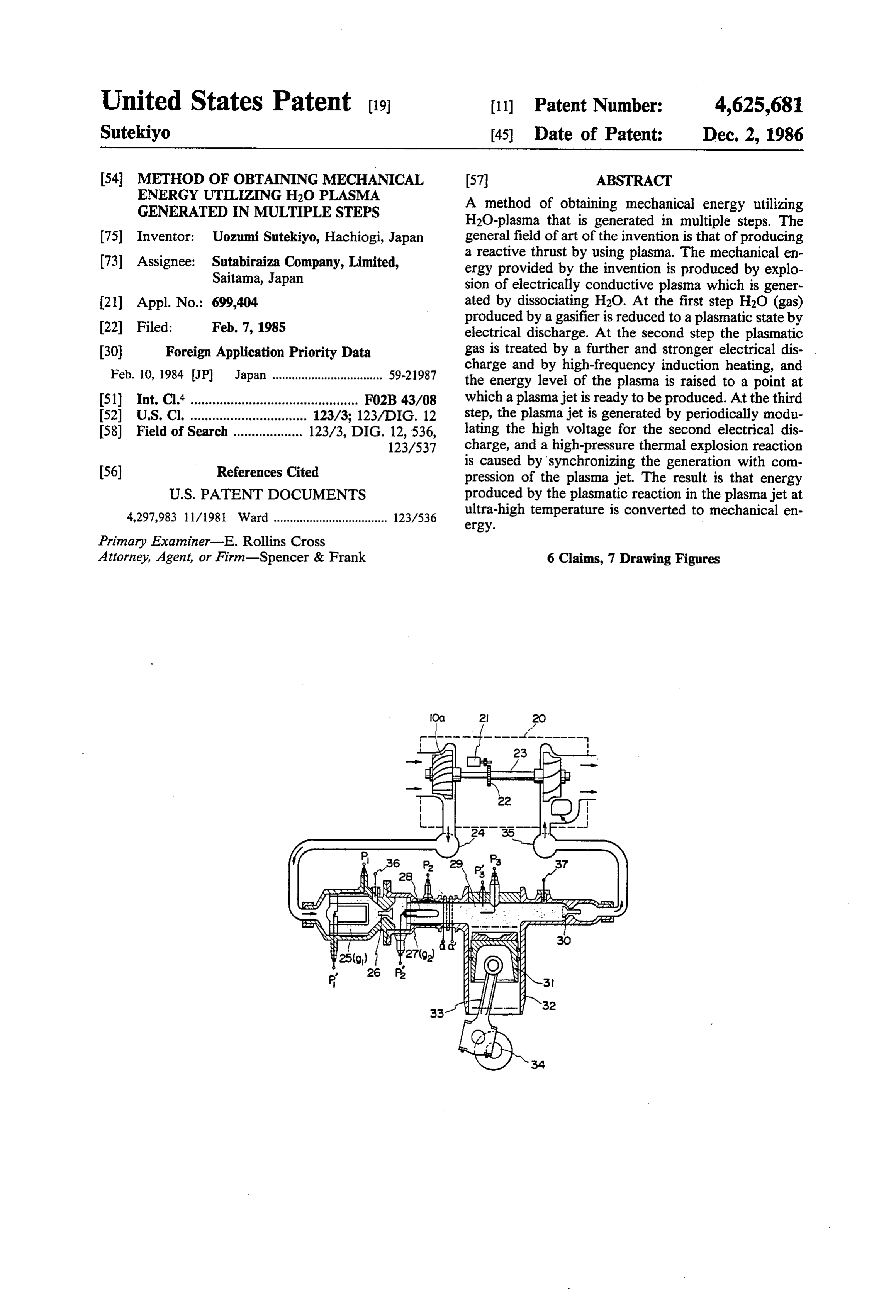
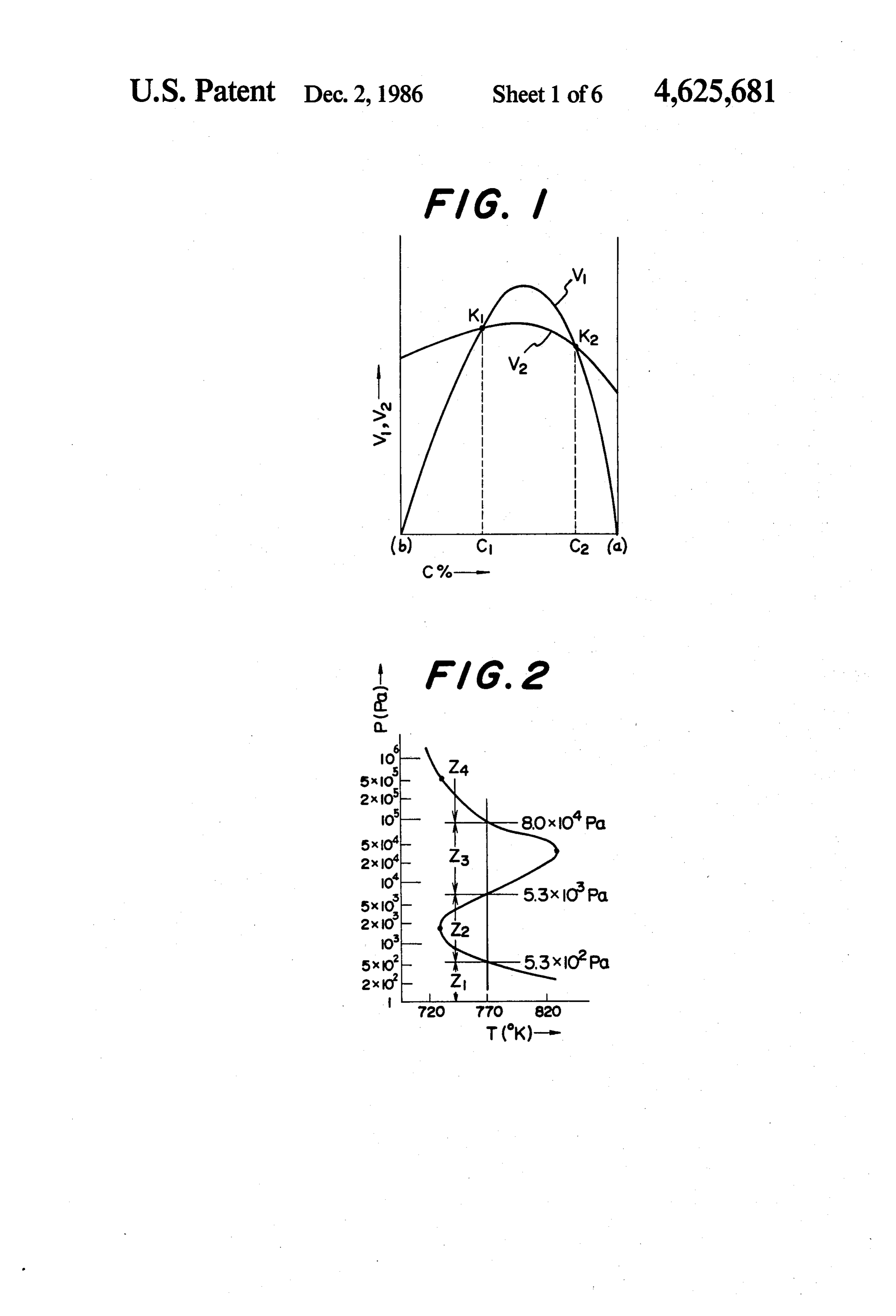
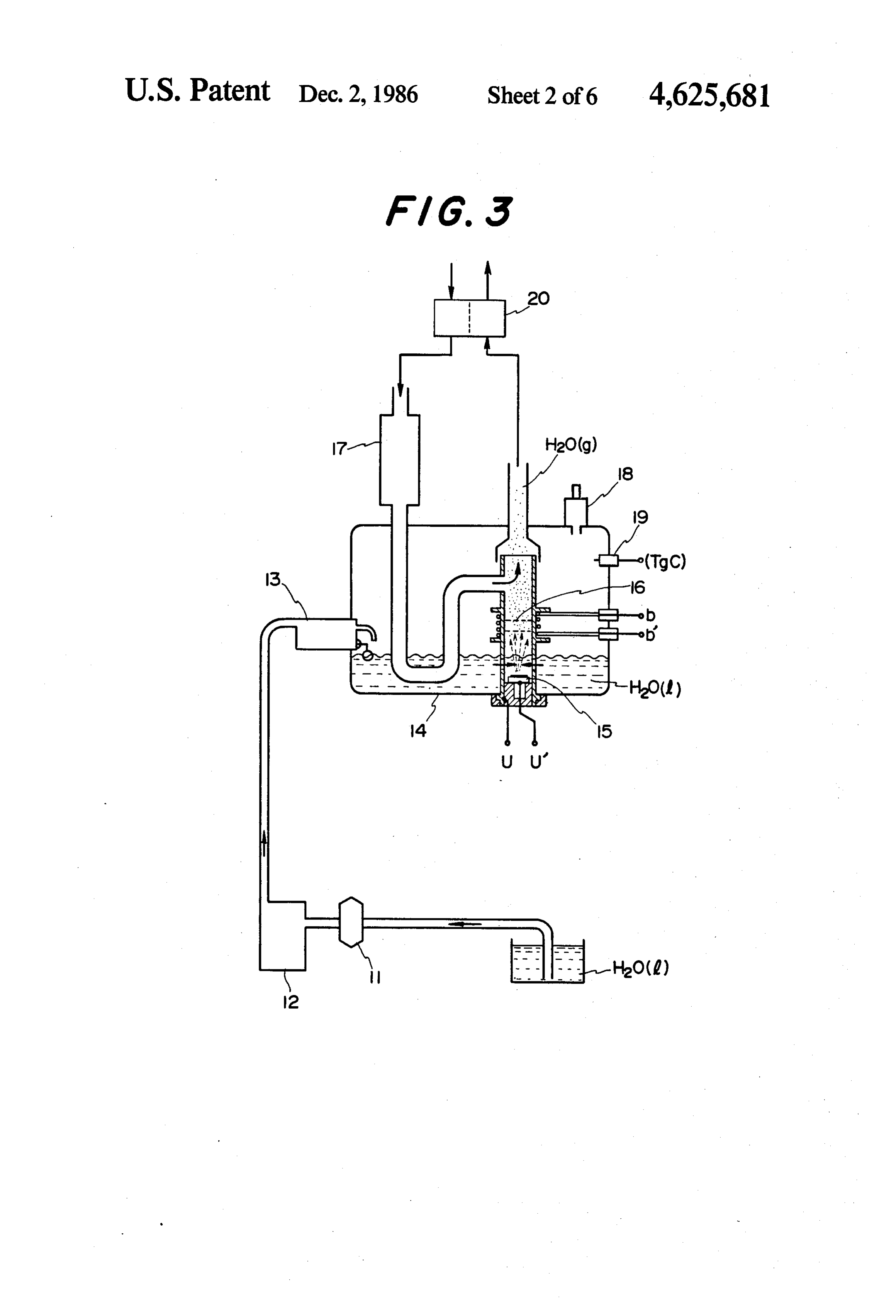
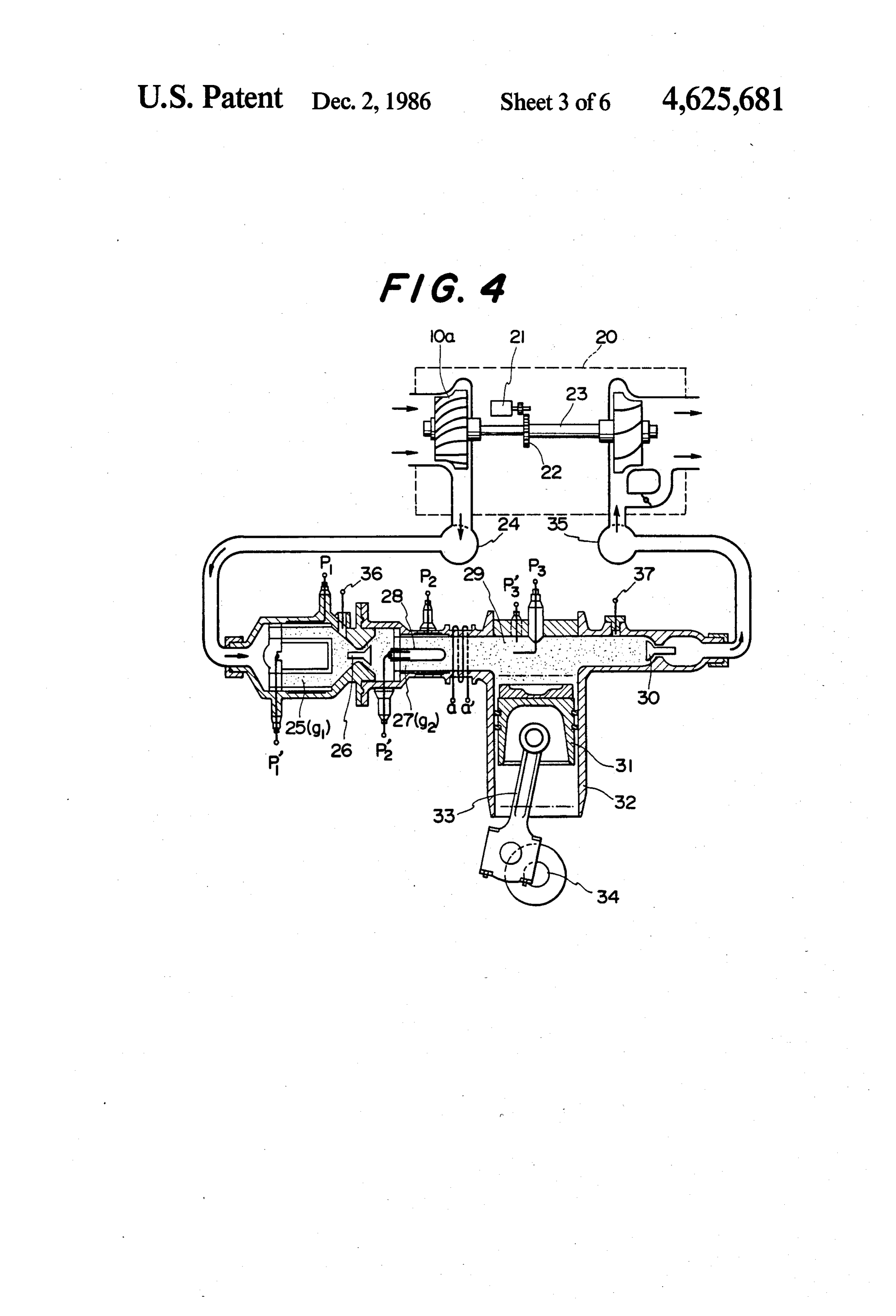
present invention, and illustrates a turbo-engine ther
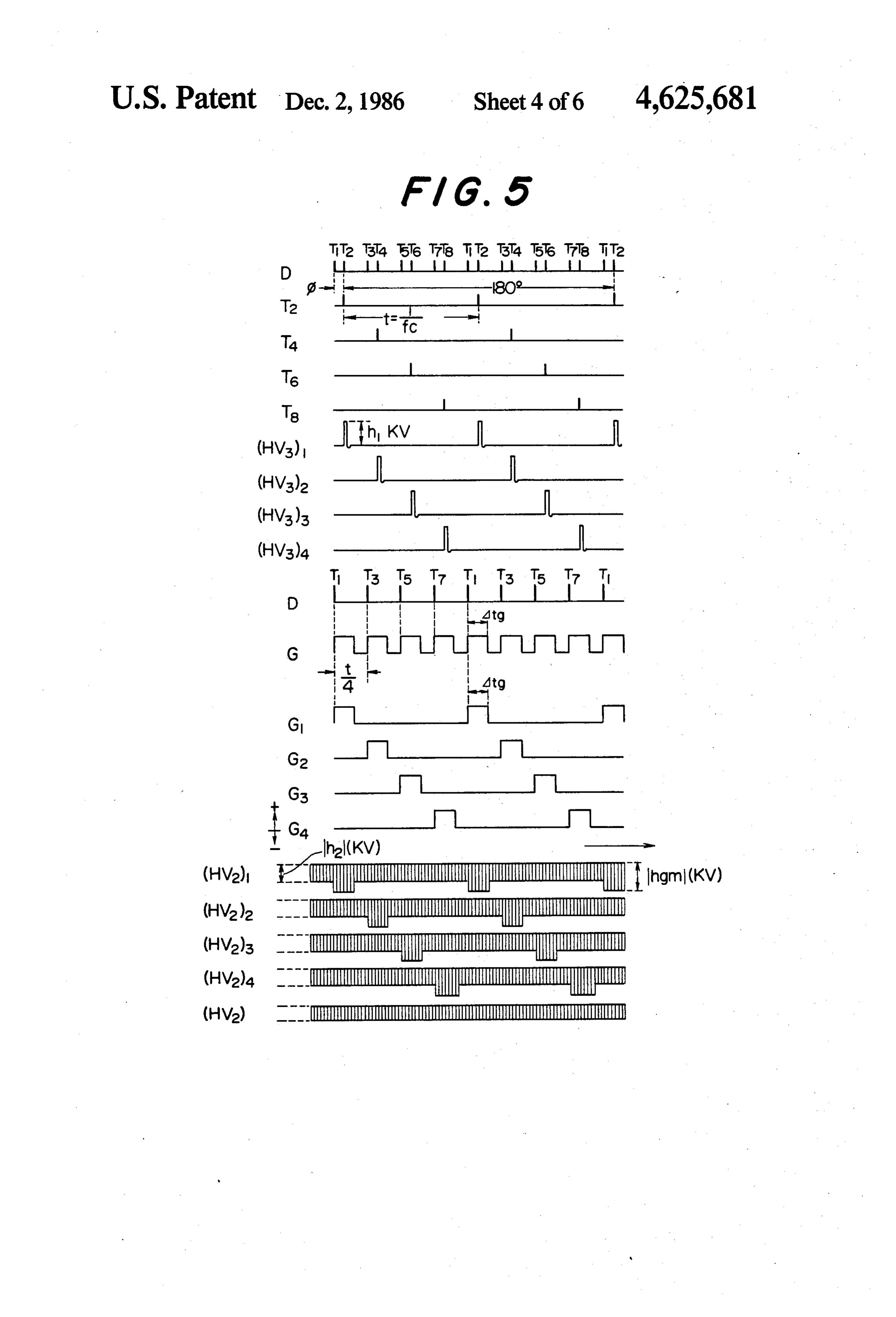
METHOD OF OBTAINING MECHANCAL mally insulated by a ceramic compound. ENERGY UTILIZING H2O PLASMA GENERATED FIG. 5 is a group of waveform diagrams illustrating IN MULTIPLE STEPS the correlations and timing of a series of external pulse signals to operate the system and a series of gate modu
BACKGROUND OF THE INVENTION lation pulse signals for controlling the plasma jet, etc., in The field of art to which the present invention per a four-cycle engine having elements of the form illus tains is "Using plasma to produce a reactive propulsive trated in FIG. 4.
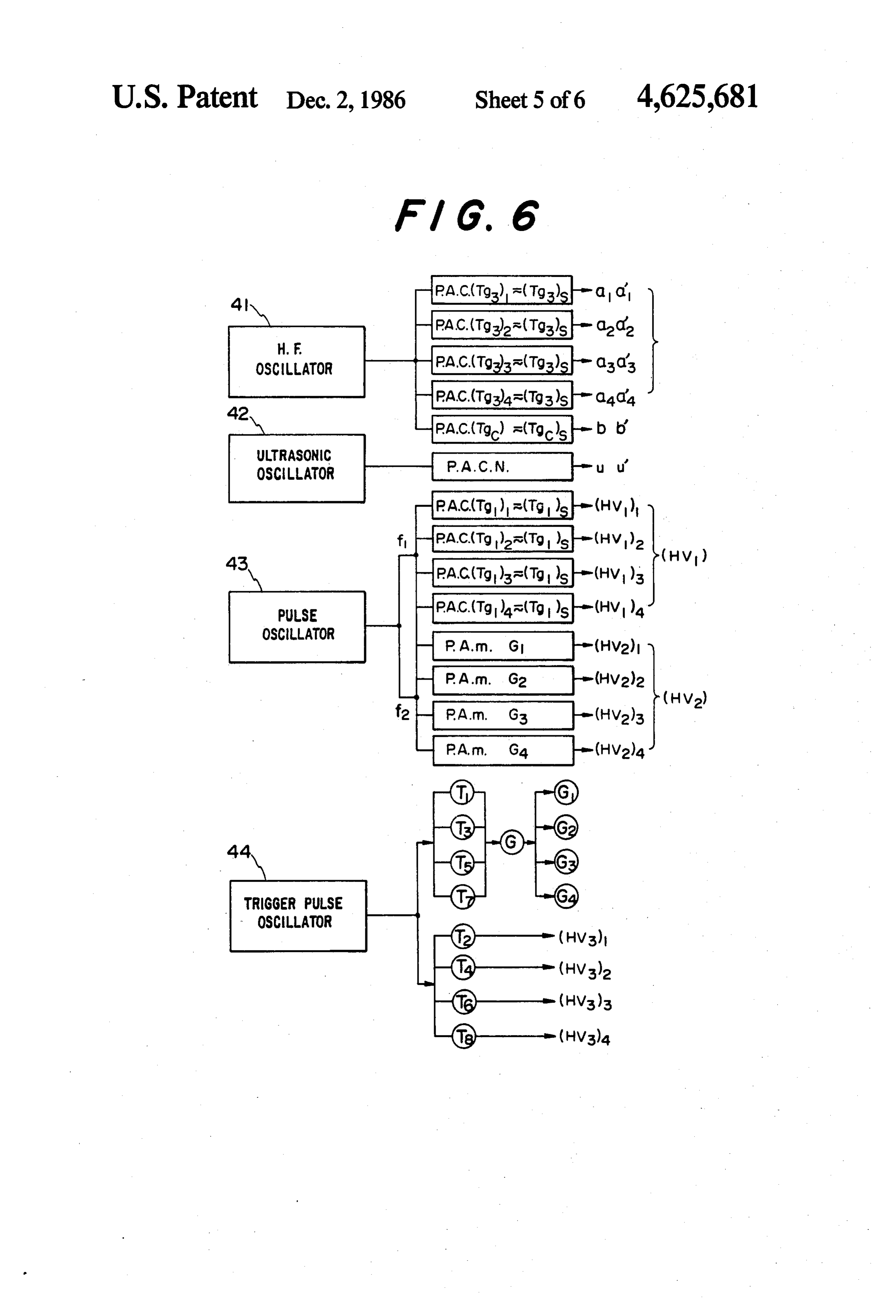
thrust,' classified FO3H 1/00 in the International Classi FIG. 6 is a schematic diagram of one form of an 10 electronic system which can be employed with a four fication.
The present invention relates to novel subject matter cycle engine having elements of the form illustrated in without precedent in the prior art. Today, gasoline FIG. 4.
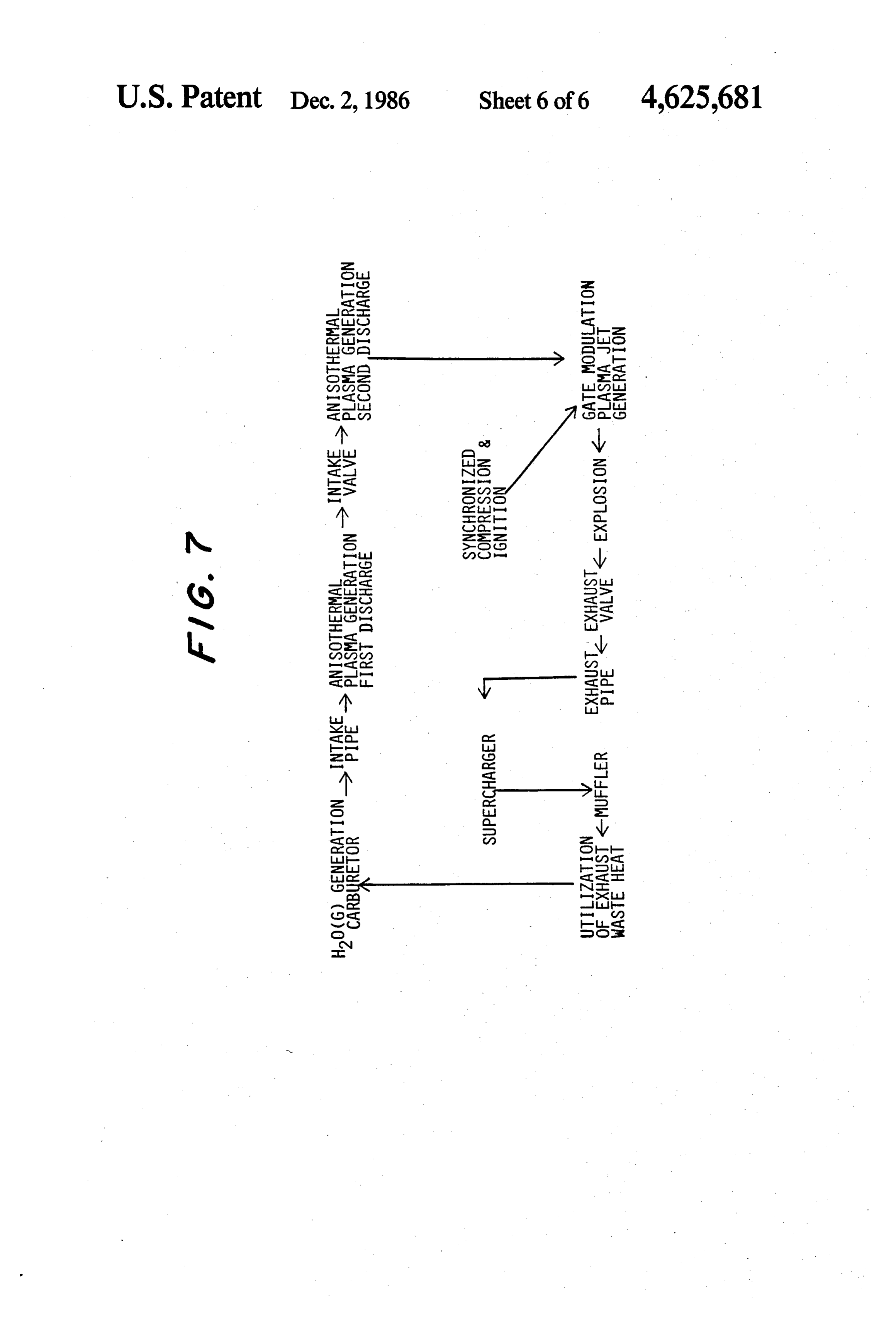
occupies an important position as a material to produce FIG. 7 is a system flow chart of a method in accor mechanical energy; however the use thereof entails 15 dance with the present invention.
high cost, and the waste produced from the use causes environmental pollution. Various efforts have been DETAILED DESCRIPTION OF THE made to eliminate or reduce such pollution for the main INVENTION tenance of human health, but as of yet no effort that has Generally, when oxygen is mixed with combustible been made to cope with these problems has resulted in 20 gas and a part of the gas mixture is ignited, a reaction radically alternative means. will take place uniformly in the gas mixture, and the BRIEF SUMMARY OF THE INVENTION reaction speed, that is, the heat generation rate, is re markably high. On the other hand the heat is dispersed
This invention relates to a method of obtaining me chanical energy, wherein H2O(g) (that is, H2O gas) is in a gas of low heat conductivity, so the heat generation rate is always higher than the heat dispersion rate. This generated from H2O(l) (liquid) by a gasifier, and the reaction
H2O(g) is thereafter dissociated by multi-step electrical tion' and,may as be identified as "unsteady-state combus the materials produced by the combustion discharge and induction heating to generate an electri cally conductive plasma confined in a cylinder. A con are always gas or vapor, the unsteady-state combustion centration of reactive free radicals in the plasma is sub causes anand explosion. Oxy-hydrogen detonating gas ex sequently treated by means of time gate modulation of a 30 plosions are of this vaporized gasoline/air mixture explosions type. Such explosions arise when the rate of high voltage for the discharge at the final step to period ically produce a plasma jet having a temperature of heat generation by the combustion exceeds the rate of heat dispersion, so that for an explosion there exists a thousands of degrees of Kelvin (K.) at the center of the certain cylinder. The degree of dissociation then sharply in limit on the composition of a gas mixture. creases, and the plasma is compressed and ignited in 35 tionship FIG. 1 is a basic explanatory graph showing the rela synchronization therewith to induce an explosive reac between the rate of heat generation (V1) and tion to obtain mechanical energy. the rate of heat dispersion (V2) when an explosion takes It is an object of the invention to provide a method to place in a mixture of a combustible gas A and a gas B. obtain mechanical energy using H2O as a reactive inter The X-axis represents the concentration C of combusti mediary. ble gas A contained in the gas mixture, this concentra Another object of the invention is to provide a tion increasing from left to right. At the left end point method to obtain mechanical energy utilizing a sub (b) on the X-axis, the concentration C of gas A is 0% (so stance whose product materials in a combustion reac that gas B, such as oxygen or air, is present at 100%), tion are completely free from pollution. and at the right end point (a) on the axis, the concentra A further object of the invention is to provide a 45 tion C of the combustible gas, for example, hydrogen, method to obtain mechanical energy in which a thermal gasoline etc. is 100%. The reaction speed, that is, the explosion reaction is caused using only hydrogen and heat generation rate, is 0 at points (a) and (b), where the oxygen produced by dissociation of H2O. concentration of the combustible gas is respectively 0% The above and further objects and novel features of and 100%, and therefore both ends of the curve (V1) are this invention will more fully appear from the following 50 at the zero point on the Y-axis (rate). The curve (V) detailed description when the same is read in connec must reach its maximum at a certain point between these tion with the accompanying drawings, which are how end points. On the other hand heat dispersion takes ever only for the purpose of illustration and are not place even when gas A or gas B is at 100%, so the intended to limit scope of the invention. relationship between the composition of the gas mixture 55 and the heat dispersion rate can be shown by the curve
BRIEF DESCRIPTION OF THE DRAWINGS (V2), which must cross the curve (V1) at certain points FIG. 1 is a schematic diagram presented for assist within a certain range on the Y-axis and between the ance in explaining the relationship between the heat endpoints (a) and (b) on the X-axis. At a given tempera generation rate V1 and the heat dispersion rate V2 in an ture, assuming that the relative position of the heat explosion of a gas mixture. 60 generation curve (V1) and the heat dispersion curve FIG. 2 is a diagram illustrating characteristics in the (V2) is as indicated in the FIG. 1, the curves cross each relationship between temperature T (K.) and pressure other at two points K1 and K2, and the heat generation P (Pa) in a hydrogen explosion. rate (V1) is above the heat dispersion rate (V2) at all FIG. 3 is a schematic vertical sectional view of an points between points K1 and K2, which correspond example of a gasifier used to produce H2O(g) from 65 respectively to concentrations C1 and C2 of combustible H2O(l) during an initial step. gas. Therefore, at such temperature as described above, FIG. 4 is a vertical, partially fragmentary schematic the use of a gas mixture having a composition falling view of an example of a device for carrying out the between C1 and C2 will cause an explosion, and such
Page 9
temperature corresponds to the ignition temperature, or exceeds this latter figure, i.e., in zone Z4, a high-pres triggering temperature for a gas mixture having the sure explosion (also called a thermal explosion) occurs. composition shown by C1 and C2. As a practical matter, In a thermal explosion, the speed of the reaction in the temperature which causes ignition in various gas creases rapidly, and the heat generation rate also in mixtures is near red heat (773 K. - 873 K., where K. creases rapidly at a certain temperature in proportion to indicates degrees Kelvin). It can be said that each gas the increase of the pressure. The explosions in the pres mixture has a peculiar range of combustion composition ent invention relate to explosions taking place in zone of its own. Z4.
Since the combustible gas A described above is hy Now, at the start of a chain reaction: drogen in the present invention, the explosion range of O H2-2H. (2) or hydrogen will be described. The explosive range of hydrogen gas mixed with air is C1&4% - C2a-75% in H2--O-HO2-i-H. (3) volume % (physics class 162 (578) P, "the Book of
Chronological Scientific Data' published by Maruzen 15 and during propagation of the chain reaction: K. K., 1982). It is to be noted here that, at composition
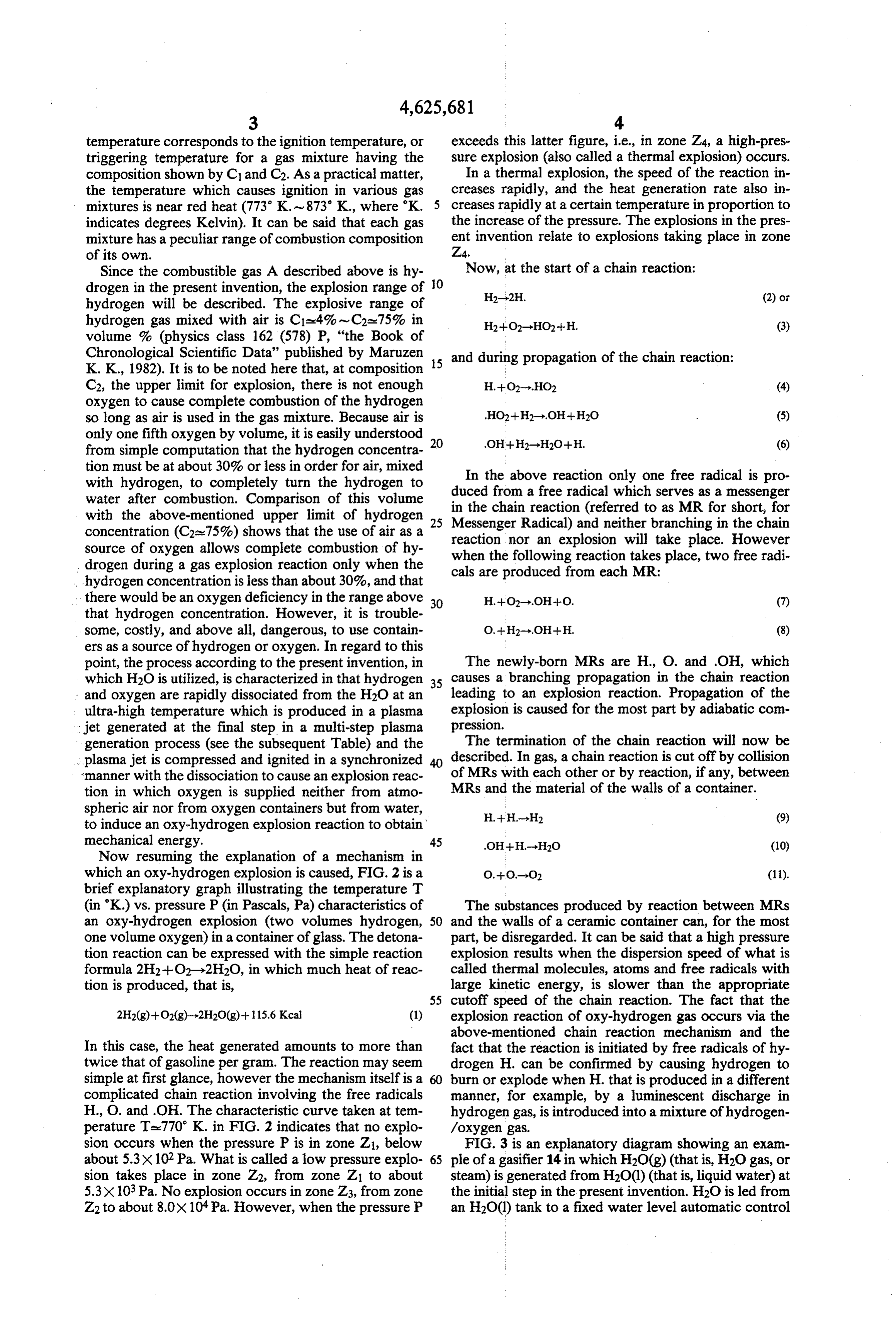
C2, the upper limit for explosion, there is not enough H.--O-HO2 (4) oxygen to cause complete combustion of the hydrogen so long as air is used in the gas mixture. Because air is only one fifth oxygen by volume, it is easily understood 20 .OH--H2-H2O+H. (6) from simple computation that the hydrogen concentra tion must be at about 30% or less in order for air, mixed with hydrogen, to completely turn the hydrogen to duced In the above reaction only one free radical is pro water after combustion. Comparison of this volume in the chain from a free radical which serves as a messenger with the above-mentioned upper limit of hydrogen 25 Messenger Radical) reaction (referred to as MR for short, for concentration (C2a.75%) shows that the use of air as a reaction nor an explosionand neither branching in the chain source of oxygen allows complete combustion of hy when the following reactionwill take place. However drogen during a gas explosion reaction only when the cals are produced from each MR: place, two free radi takes hydrogen concentration is less than about 30%, and that there would be an oxygen deficiency in the range above 30 H.--O-OH--O. (7) that hydrogen concentration. However, it is trouble some, costly, and above all, dangerous, to use contain O.--H2-OH--H. (8) ers as a source of hydrogen or oxygen. In regard to this point, the process according to the present invention, in The newly-born MRs are H. O. and OH, which which H2O is utilized, is characterized in that hydrogen 35 causes a branching propagation in the chain reaction and oxygen are rapidly dissociated from the H2O at an leading to an explosion reaction. Propagation of the ultra-high temperature which is produced in a plasma explosion is caused for the most part by adiabatic com jet generated at the final step in a multi-step plasma pression.
generation process (see the subsequent Table) and the The termination of the chain reaction will now be plasma jet is compressed and ignited in a synchronized described. In gas, a chain reaction is cut off by collision manner with the dissociation to cause an explosion reac of MRs with each other or by reaction, if any, between tion in which oxygen is supplied neither from atmo MRs and the material of the walls of a container. spheric air nor from oxygen containers but from water, H.-H...-H2 (9) to induce an oxy-hydrogen explosion reaction to obtain' mechanical energy. 45 .OH--H...-H2O (10) Now resuming the explanation of a mechanism in which an oxy-hydrogen explosion is caused, FIG. 2 is a O.-O.--O2 (11). brief explanatory graph illustrating the temperature T (in K.) vs. pressure P (in Pascals, Pa) characteristics of The substances produced by reaction between MRs an oxy-hydrogen explosion (two volumes hydrogen, 50 and the walls of a ceramic container can, for the most one volume oxygen) in a container of glass. The detona part, be disregarded. It can be said that a high pressure tion reaction can be expressed with the simple reaction explosion results when the dispersion speed of what is formula 2H2--O2-2H2O, in which much heat of reac called thermal molecules, atoms and free radicals with tion is produced, that is, large kinetic energy, is slower than the appropriate 55 cutoff speed of the chain reaction. The fact that the 2H2(g)--O2(g)-2H2O(g)--115.6 Kcal (1) explosion reaction of oxy-hydrogen gas occurs via the above-mentioned chain reaction mechanism and the
In this case, the heat generated amounts to more than fact that the reaction is initiated by free radicals of hy twice that of gasoline per gram. The reaction may seem drogen H. can be confirmed by causing hydrogen to simple at first glance, however the mechanism itself is a burn or explode when H. that is produced in a different complicated chain reaction involving the free radicals manner, for example, by a luminescent discharge in H., O. and OH. The characteristic curve taken at tem hydrogen gas, is introduced into a mixture of hydrogen perature Ta-770 K. in FIG. 2 indicates that no explo /oxygen gas.
sion occurs when the pressure P is in zone Z1, below FIG. 3 is an explanatory diagram showing an exam about 5.3X 10² Pa. What is called a low pressure explo 65 ple of a gasifier 14 in which H2O(g) (that is, H2O gas, or sion takes place in zone Z2, from zone Z1 to about steam) is generated from H2O(l) (that is, liquid water) at 5.3X 10³Pa. No explosion occurs in zone Z3, from zone the initial step in the present invention. H2O is led from Z2 to about 8.0X 10. Pa. However, when the pressure P an H2O(l) tank to a fixed water level automatic control
Page 10
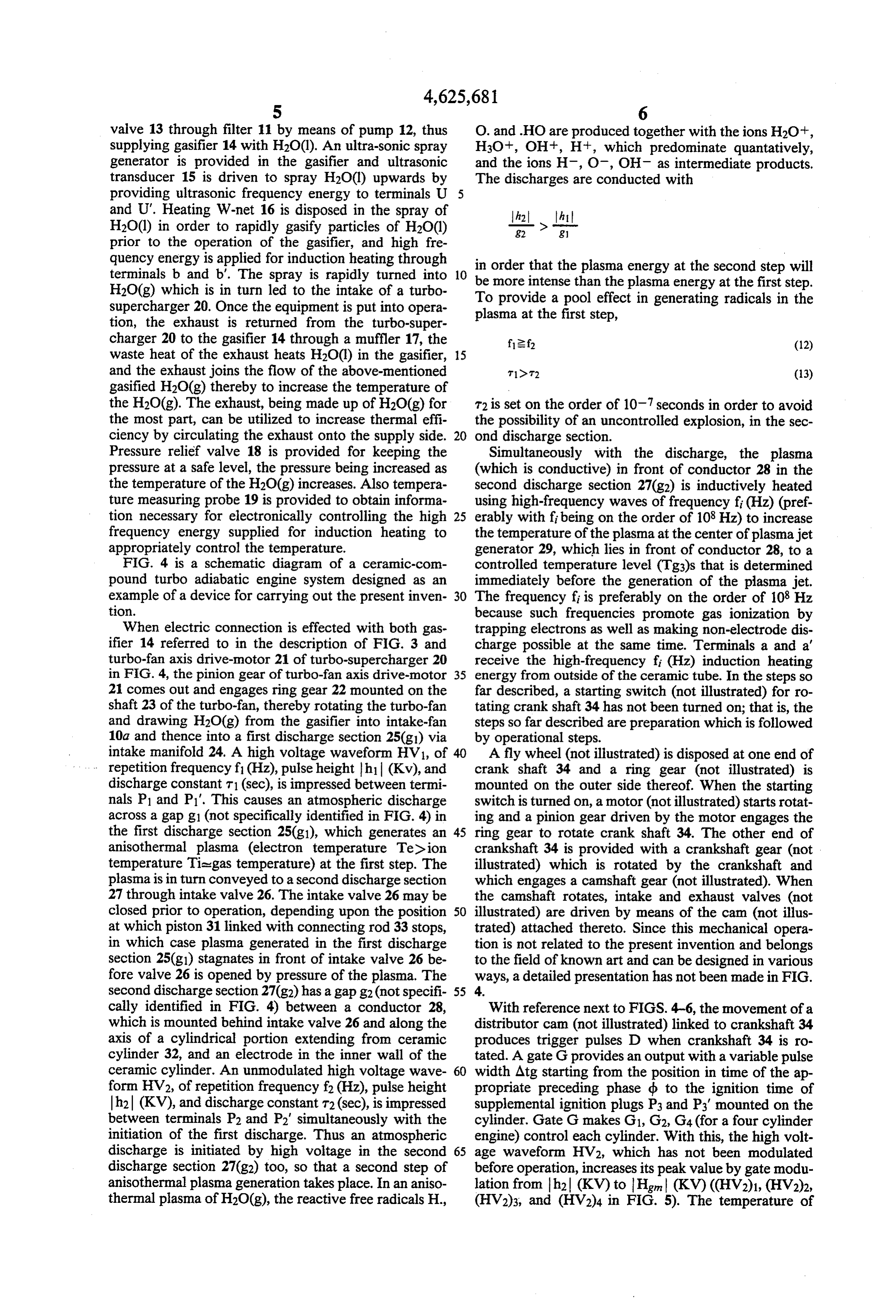
valve 13 through filter 11 by means of pump 12, thus O. and .HO are produced together with the ions H2O, supplying gasifier 14 with H2O(l). An ultra-sonic spray H3O+, OH, H+, which predominate quantatively, generator is provided in the gasifier and ultrasonic and the ions H, O, OH as intermediate products. transducer 15 is driven to spray H2O(l) upwards by The discharges are conducted with providing ultrasonic frequency energy to terminals U 5 and U'. Heating W-net 16 is disposed in the spray of h2. ht
H2O(l) in order to rapidly gasify particles of H2O(l) -- > ---
prior to the operation of the gasifier, and high fre quency energy is applied for induction heating through terminals b and b'. The spray is rapidly turned into 10 in order that the plasma energy at the second step will H2O(g) which is in turn led to the intake of a turbo Tomore be intense than the plasma energy at the first step. supercharger 20. Once the equipment is put into opera plasma at thea first provide pool effect in generating radicals in the step, tion, the exhaust is returned from the turbo-super charger 20 to the gasifier 14 through a muffler 17, the f2f (12) waste heat of the exhaust heats H2O(l) in the gasifier, 15 and the exhaust joins the flow of the above-mentioned to t? (13) gasified H2O(g) thereby to increase the temperature of the H2O(g). The exhaust, being made up of H2O(g) for T2 is set on the order of 107 seconds in order to avoid the most part, can be utilized to increase thermal effi the possibility of an uncontrolled explosion, in the sec ciency by circulating the exhaust onto the supply side. 20 ond discharge section.
Pressure relief valve 18 is provided for keeping the Simultaneously with the discharge, the plasma pressure at a safe level, the pressure being increased as (which is conductive) in front of conductor 28 in the the temperature of the H2O(g) increases. Also tempera second discharge section 27(g2) is inductively heated ture measuring probe 19 is provided to obtain informa using high-frequency waves of frequency fi (Hz) (pref tion necessary for electronically controlling the high 25 erably with fi being on the order of 108 Hz) to increase frequency energy supplied for induction heating to the temperature of the plasma at the center of plasmajet appropriately control the temperature. generator 29, which lies in front of conductor 28, to a FIG. 4 is a schematic diagram of a ceramic-com controlled temperature level (Tg3)s that is determined pound turbo adiabatic engine system designed as an immediately before the generation of the plasma jet. example of a device for carrying out the present inven 30 The frequency fi is preferably on the order of 108 Hz tion. because such frequencies promote gas ionization by When electric connection is effected with both gas trapping electrons as well as making non-electrode dis ifier 14 referred to in the description of FIG. 3 and charge possible at the same time. Terminals a and a turbo-fan axis drive-motor 21 of turbo-supercharger 20 receive the high-frequency fi (Hz) induction heating in FIG. 4, the pinion gear of turbo-fan axis drive-motor 35 energy from outside of the ceramic tube. In the steps so 21 comes out and engages ring gear 22 mounted on the far described, a starting switch (not illustrated) for ro shaft 23 of the turbo-fan, thereby rotating the turbo-fan tating crankshaft 34 has not been turned on; that is, the and drawing H2O(g) from the gasifier into intake-fan steps so far described are preparation which is followed 10a and thence into a first discharge section 25(g) via by operational steps.
intake manifold 24. A high voltage waveform HV1, of 40 A fly wheel (not illustrated) is disposed at one end of repetition frequency f1 (Hz), pulse height h (Kv), and crank shaft 34 and a ring gear (not illustrated) is discharge constant T1 (sec), is impressed between termi mounted on the outer side thereof. When the starting nals P1 and P1". This causes an atmospheric discharge switch is turned on, a motor (not illustrated) starts rotat across a gap g1 (not specifically identified in FIG. 4) in ing and a pinion gear driven by the motor engages the the first discharge section 25(g1), which generates an 45 ring gear to rotate crank shaft 34. The other end of anisothermal plasma (electron temperature Tedion crankshaft 34 is provided with a crankshaft gear (not temperature Tiegas temperature) at the first step. The illustrated) which is rotated by the crankshaft and plasma is in turn conveyed to a second discharge section which engages a camshaft gear (not illustrated). When 27 through intake valve 26. The intake valve 26 may be the camshaft rotates, intake and exhaust valves (not closed prior to operation, depending upon the position 50 illustrated) are driven by means of the cam (not illus at which piston 31 linked with connecting rod 33 stops, trated) attached thereto. Since this mechanical opera in which case plasma generated in the first discharge tion is not related to the present invention and belongs section 25(g) stagnates in front of intake valve 26 be to the field of known art and can be designed in various fore valve 26 is opened by pressure of the plasma. The ways, a detailed presentation has not been made in FIG. second discharge section 27(g2) has a gap g2(not specifi 55 4.
cally identified in FIG. 4) between a conductor 28, With reference next to FIGS. 4-6, the movement of a which is mounted behind intake valve 26 and along the distributor cam (not illustrated) linked to crankshaft 34 axis of a cylindrical portion extending from ceramic produces trigger pulses D when crankshaft 34 is ro cylinder 32, and an electrode in the inner wall of the tated. A gate G provides an output with a variable pulse ceramic cylinder. An unmodulated high voltage wave 60 width Atg starting from the position in time of the ap form HV2, of repetition frequency f2 (Hz), pulse height propriate preceding phase db to the ignition time of h2 (KV), and discharge constant t2 (sec), is impressed supplemental ignition plugs P3 and P3' mounted on the between terminals P2 and P2" simultaneously with the cylinder. Gate G makes G1, G2, G4 (for a four cylinder initiation of the first discharge. Thus an atmospheric engine) control each cylinder. With this, the high volt discharge is initiated by high voltage in the second 65 age waveform HV2, which has not been modulated discharge section 27(g2) too, so that a second step of before operation, increases its peak value by gate modu anisothermal plasma generation takes place. In an aniso lation from h (KV) to Hgn (KV) ((HV2)1, (HV2)2, thermal plasma of H2O(g), the reactive free radicals H., (HV2)3, and (HV2)4 in FIG. 5). The temperature of
Page 11
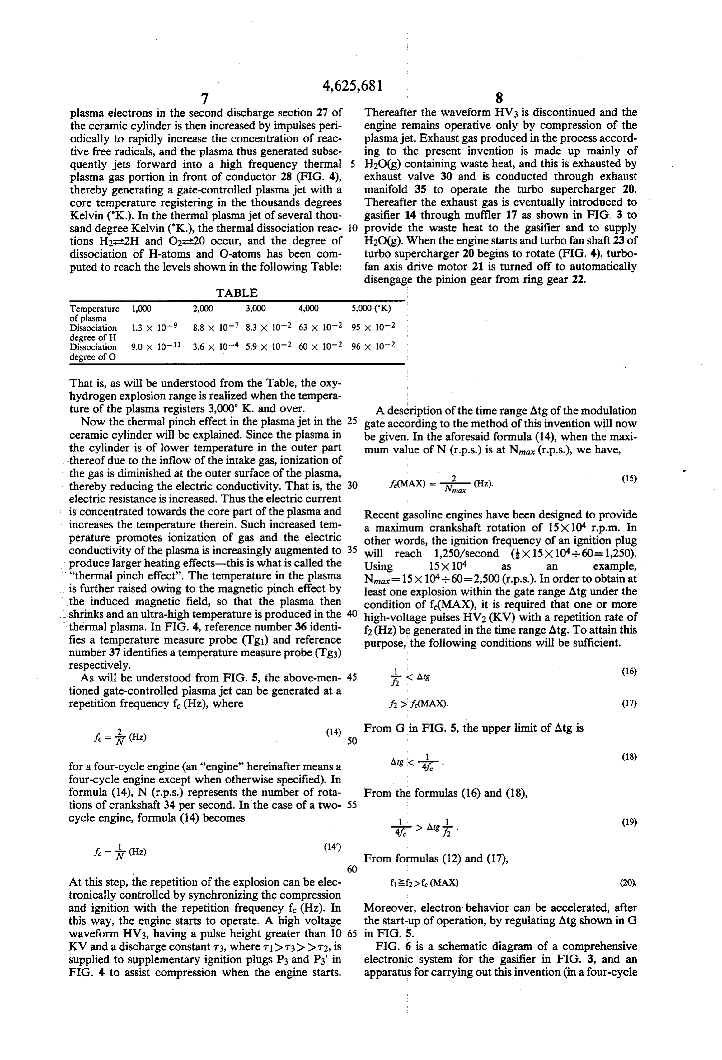
plasma electrons in the second discharge section 27 of Thereafter the waveform HV3 is discontinued and the the ceramic cylinder is then increased by impulses peri engine remains operative only by compression of the odically to rapidly increase the concentration of reac plasma jet. Exhaust gas produced in the process accord tive free radicals, and the plasma thus generated subse ing to the present invention is made up mainly of quently jets forward into a high frequency thermal H2O(g) containing waste heat, and this is exhausted by plasma gas portion in front of conductor 28 (FIG. 4), exhaust valve 30 and is conducted through exhaust thereby generating a gate-controlled plasma jet with a manifold 35 to operate the turbo supercharger 20. core temperature registering in the thousands degrees Thereafter the exhaust gas is eventually introduced to Kelvin (K.). In the thermal plasma jet of several thou gasifier 14 through muffler 17 as shown in FIG. 3 to sand degree Kelvin (K.), the thermal dissociation reac O provide the waste heat to the gasifier and to supply tions H2-2H and O2e20 occur, and the degree of H2O(g). When the engine starts and turbofan shaft 23 of dissociation of H-atoms and O-atoms has been com turbo supercharger 20 begins to rotate (FIG. 4), turbo puted to reach the levels shown in the following Table: fan axis drive motor 21 is turned off to automatically disengage the pinion gear from ring gear 22.
TABLE
Temperature 1,000 2,000 3,000 4,000 5,000 (K) of plasma
Dissociation 1.3 x 10⁻⁹ 8.8 x 10⁻⁷ 8.3 x 10⁻² 63 x 10-2 95 x 102 degree of H
Dissociation 9.0 x 10⁻¹¹ 3.6 x 10⁻⁴ 5.9 x 10⁻² 60 x 102 96 x 102 degree of O
That is, as will be understood from the Table, the oxy hydrogen explosion range is realized when the tempera ture of the plasma registers 3,000 K. and over. A description of the time range Atgofthe modulation Now the thermal pinch effect in the plasma jet in the 25 gate according to the method of this invention will now ceramic cylinder will be explained. Since the plasma in be given. In the aforesaid formula (14), when the maxi the cylinder is of lower temperature in the outer part mum value of N (r.p.s.) is at Nnax (r.p.s.), we have, thereof due to the inflow of the intake gas, ionization of the gas is diminished at the outer surface of the plasma, 2
thereby reducing the electric conductivity. That is, the 30 (Hz). electric resistance is increased. Thus the electric current is concentrated towards the core part of the plasma and Recent gasoline engines have been designed to provide increases the temperature therein. Such increased tem a maximum crankshaft rotation of 15X10 rp.m. In perature promotes ionization of gas and the electric other words, the ignition frequency of an ignition plug conductivity of the plasma is increasingly augmented to 35 will reach 1,250/second (x15x10-i-60=1,250). produce larger heating effects-this is what is called the Using 15X104 2S 2 example, . "thermal pinch effect”. The temperature in the plasma N=15x10-i-60=2,500 (r.p.s.). In order to obtain at is further raised owing to the magnetic pinch effect by least one explosion within the gate range Atgunder the the induced magnetic field, so that the plasma then condition of f(MAX), it is required that one or more shrinks and an ultra-high temperature is produced in the high-voltage pulses HV2 (KV) with a repetition rate of thermal plasma. In FIG. 4, reference number 36 identi f2 (Hz) be generated in the time range Atg. To attain this fies a temperature measure probe (Tg1) and reference purpose, the following conditions will be sufficient. number 37 identifies a temperature measure probe (Tg3) respectively. 1
As will be understood from FIG. 5, the above-men 45 < Atg (16) tioned gate-controlled plasma jet can be generated at a repetition frequency f. (Hz), where f> f(MAX). (17)
f = i. (Hz) (14) 50 From G in FIG. 5, the upper limit of Atg is
for a four-cycle engine (an "engine' hereinafter means a four-cycle engine except when otherwise specified). In formula (14), N (r.p.s.) represents the number of rota From the formulas (16) and (18), tions of crankshaft 34 per second. In the case of a two 55 cycle engine, formula (14) becomes . (19) f. = (Hz) (14") From formulas (12) and (17),
At this step, the repetition of the explosion can be elec f2f>f (MAX) (20). tronically controlled by synchronizing the compression and ignition with the repetition frequency f. (Hz). In Moreover, electron behavior can be accelerated, after this way, the engine starts to operate. A high voltage the start-up of operation, by regulating Atg shown in G waveform HV3, having a pulse height greater than 10 65 in FIG. 5.
KV and a discharge constant T3, where T1> T3) > T2, is FIG. 6 is a schematic diagram of a comprehensive supplied to supplementary ignition plugs P3 and P3' in electronic system for the gasifier in FIG. 3, and an FIG. 4 to assist compression when the engine starts, apparatus for carrying out this invention (in a four-cycle
Page 12
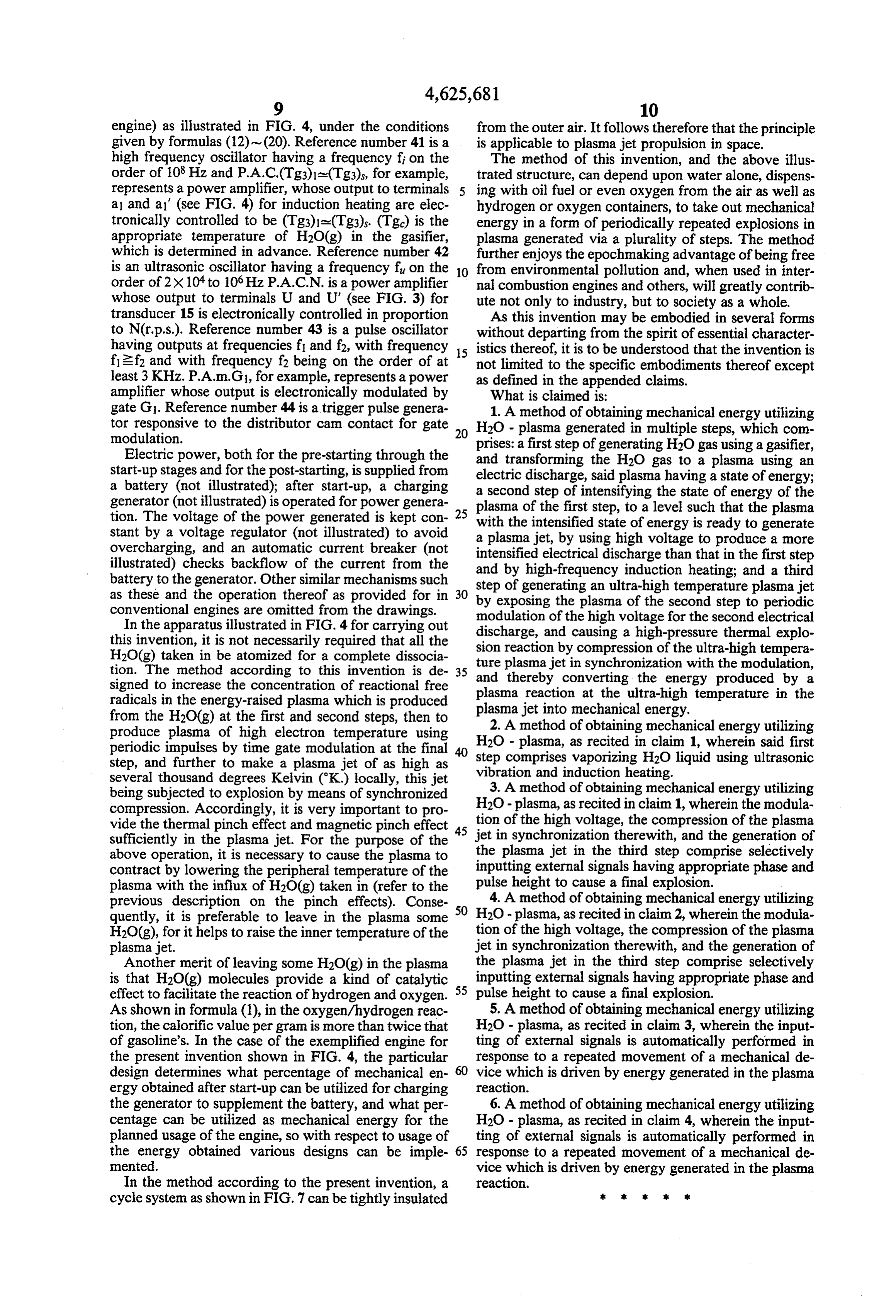
engine) as illustrated in FIG. 4, under the conditions from the outer air. It follows therefore that the principle given by formulas (12) - (20). Reference number 41 is a is applicable to plasma jet propulsion in space. high frequency oscillator having a frequency fi on the The method of this invention, and the above illus order of 108 Hz and P.A.C.(Tg3)1a(Tg3), for example, trated structure, can depend upon water alone, dispens represents a power amplifier, whose output to terminals ing with oil fuel or even oxygen from the air as well as al and al" (see FIG. 4) for induction heating are elec hydrogen or oxygen containers, to take out mechanical tronically controlled to be (Tg3)1a(Tg3). (Tg) is the energy in a form of periodically repeated explosions in appropriate temperature of H2O(g) in the gasifier, plasma generated via a plurality of steps. The method which is determined in advance. Reference number 42 further enjoys the epochmaking advantage of being free is an ultrasonic oscillator having a frequency fu on the 10 from environmental pollution and, when used in inter order of 2x10 to 106 Hz P.A.C.N. is a power amplifier nal combustion engines and others, will greatly contrib whose output to terminals U and U" (see FIG. 3) for ute not only to industry, but to society as a whole. transducer 15 is electronically controlled in proportion As this invention may be embodied in several forms to N(r.p.s.). Reference number 43 is a pulse oscillator without departing from the spirit of essential character having outputs at frequencies f and f2, with frequency 15 istics thereof, it is to be understood that the invention is f2f2 and with frequency f2 being on the order of at not limited to the specific embodiments thereof except least 3 KHz. P.A.m.G1, for example, represents a power amplifier whose output is electronically modulated by as What defined in the appended claims. is claimed is:
gate G1. Reference number 44 is a trigger pulse genera 1. A method of obtaining mechanical energy utilizing tor responsive to the distributor cam contact for gate 20 H2O - plasma generated in multiple steps, which com modulation. prises: a first step of generating H2O gas using a gasifier, Electric power, both for the pre-starting through the and transforming the H2O gas to a plasma using an start-up stages and for the post-starting, is supplied from electric discharge, said plasma having a state of energy; a battery (not illustrated); after start-up, a charging a second step of intensifying the state of energy of the generator (not illustrated) is operated for power genera plasma of the first step, to a level such that the plasma tion. The voltage of the power generated is kept con 25 with the intensified state of energy is ready to generate stant by a voltage regulator (not illustrated) to avoid a plasma jet, by using high voltage to produce a more overcharging, and an automatic current breaker (not intensified electrical discharge than that in the first step illustrated) checks backflow of the current from the and by high-frequency induction heating; and a third battery to the generator. Other similar mechanisms such step of generating an ultra-high temperature plasma jet as these and the operation thereof as provided for in 30 by exposing the plasma of the second step to periodic conventional engines are omitted from the drawings.
In the apparatus illustrated in FIG. 4 for carrying out discharge, andthe modulation of high voltage for the second electrical causing a high-pressure thermal explo this invention, it is not necessarily required that all the sion reaction by compression of the ultra-high tempera H2O(g) taken in be atomized for a complete dissocia ture plasma jet in synchronization with the modulation, tion. The method according to this invention is de 35 and thereby converting the energy produced by a signed to increase the concentration of reactional free plasma reaction at the ultra-high temperature in the radicals in the energy-raised plasma which is produced plasma jet into mechanical energy.
from the H2O(g) at the first and second steps, then to 2. A method of obtaining mechanical energy utilizing produce plasma of high electron temperature using
H2O - plasma, as recited in claim 1, wherein said first periodic impulses by time gate modulation at the final step comprises step, and further to make a plasma jet of as high as vaporizing H2O liquid using ultrasonic several thousand degrees Kelvin (K.) locally, this jet vibration and induction heating. being subjected to explosion by means of synchronized 3. A method of obtaining mechanical energy utilizing compression. Accordingly, it is very important to pro H2O - plasma, as recited in claim 1, wherein the modula vide the thermal pinch effect and magnetic pinch effect tioninofsynchronization the high voltage, the compression of the plasma sufficiently in the plasma jet. For the purpose of the 45 jet therewith, and the generation of above operation, it is necessary to cause the plasma to the plasma jet in the third step comprise selectively contract by lowering the peripheral temperature of the inputting external signals having appropriate phase and plasma with the influx of H2O(g) taken in (refer to the pulse height to cause a final explosion. previous description on the pinch effects). Conse 50 4. A method of obtaining mechanical energy utilizing quently, it is preferable to leave in the plasma some H2O - plasma, as recited in claim 2, wherein the modula H2O(g), for it helps to raise the inner temperature of the tion of the high voltage, the compression of the plasma plasma jet. jet in synchronization therewith, and the generation of Another merit of leaving some H2O(g) in the plasma the plasma jet in the third step comprise selectively is that H2O(g) molecules provide a kind of catalytic 55 inputting external signals having appropriate phase and effect to facilitate the reaction of hydrogen and oxygen. pulse height to cause a final explosion. As shown in formula (1), in the oxygen/hydrogen reac 5. A method of obtaining mechanical energy utilizing tion, the calorific value per gram is more than twice that H2O - plasma, as recited in claim 3, wherein the input of gasoline's. In the case of the exemplified engine for ting of external signals is automatically performed in the present invention shown in FIG. 4, the particular response to a repeated movement of a mechanical de design determines what percentage of mechanical en vice which is driven by energy generated in the plasma ergy obtained after start-up can be utilized for charging reaction.
the generator to supplement the battery, and what per 6. A method of obtaining mechanical energy utilizing centage can be utilized as mechanical energy for the H2O - plasma, as recited in claim 4, wherein the input planned usage of the engine, so with respect to usage of ting of external signals is automatically performed in the energy obtained various designs can be imple 65 response to a repeated movement of a mechanical de mented. vice which is driven by energy generated in the plasma In the method according to the present invention, a reaction.
cycle system as shown in FIG. 7 can be tightly insulated k k k k 2k
Page 13
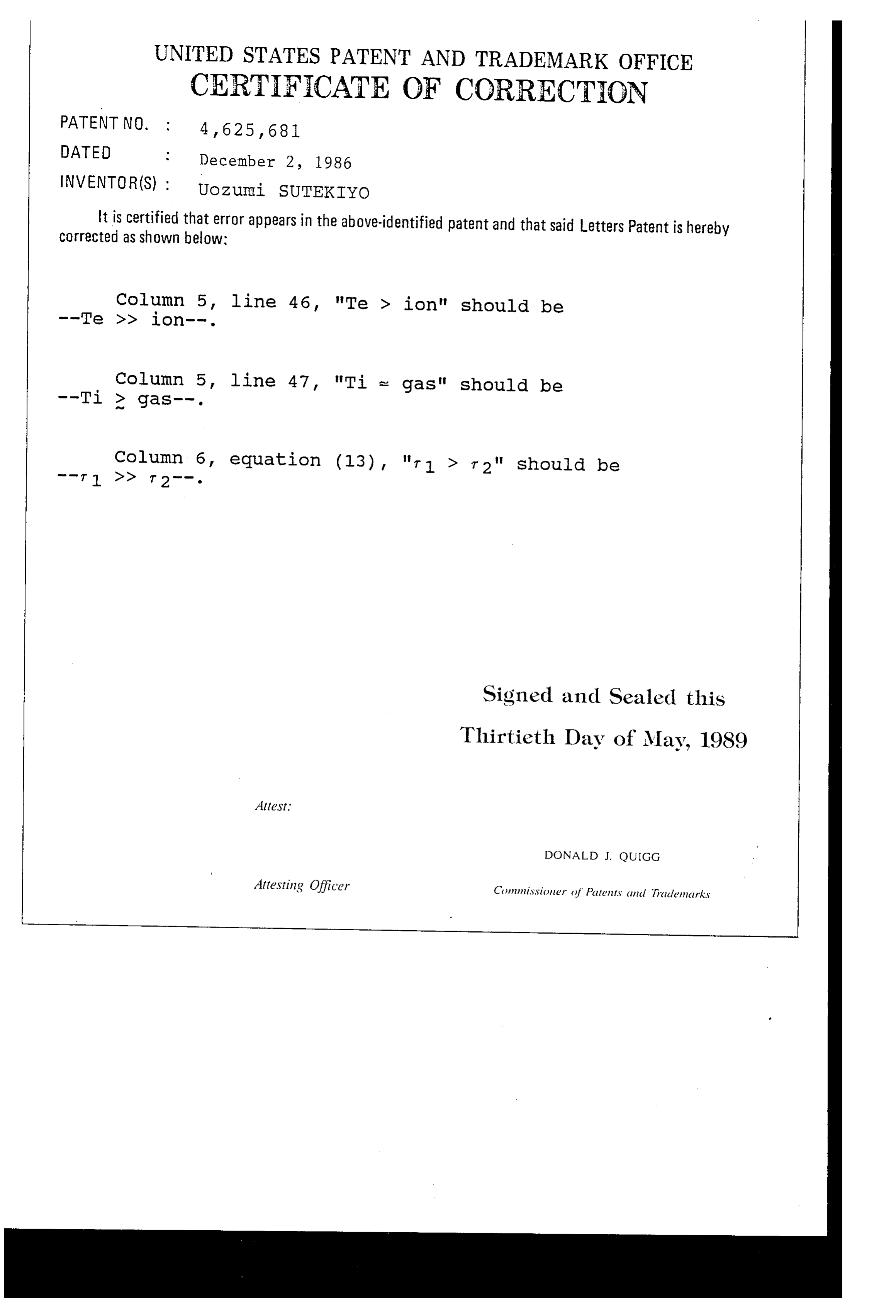
UNITED STATES PATENT AND TRADEMARK OFFICE
CERTIFICATE OF CORRECTION
DATED
December 2, 1986
INVENTOR(S) : UoZuni SUTEKIYO It is certified that error appears in the above-identified patent and that said Letters Patent is hereby Corrected as shown below:
Column 5, line 46, "Te > ion" should be
Column 5, line 47, "Ti e gas" should be
Column 6, equation (13), "r 1 > r2" should be
Signed and Sealed this
Thirtieth Day of May, 1989
Attest:
DONALD J. QUICG
Attesting Officer Commissioner of Pattents and Trademarks
Provenance
- Collection
- Cited prior art
- Original PDF
- patentimages.storage.googleapis.com →
- Filed
- 1985-02-07
- Pages
- 13
- Method
- pdftotext (the PDF's own text layer) + pdftoppm 300dpi page scans
- Source
- Google Patents bibliographic record
- Granted
- 1986-12-02
- Inventors
- Uozumi Sutekiyo; SUTABIRAIZA CO Ltd
- Transcribed from
- patentimages.storage.googleapis.com →