patent · US3577733
Rapid loading of steam turbines
4 May 1971
Page 1 — bibliographic record
United States Patent (113,577,733 (72) Inventors Eric Manuel (50 Field of Search............................................ 60/73, 105, Peterborough, Ontario, Canada; 108 James H. Moore, Jr., Scotia, N.Y.
(21) Appl. No. 822,933 56) References Cited 22) Filed May 8, 1969 UNITED STATES PATENTS (45) Patented May 4, 1971 3,338,053 8/1967 Gorzegno..................... 60/105 73 Assignee General Electric Company 32) Priority July 16, 1968 Primary Examiner-Martin P. Schwadron (33 Canada Assistant Examiner-Allen M. Ostrager 31) 25,244 Attorneys-William C. Crutcher, Frank L. Neuhauser, Oscar B. Waddell and Joseph B. Forman
(54) RAPD LOADING OFSTEAMTURBINES
3 Claims, 5 Drawing Figs. ABSTRACT: A method for loading a steam turbine and trans (52) U.S. Cl........................................................ 60/105, ferring from full arc to partial arc admission during loading while maintaining a constant rate of heating, so as to eliminate 60/73 the cooling and reheating which previously took place during 51 Int. Cli....................................................... F01k 13/02 a transfer at constant load.
STEAM FROM STEAM GENERATOR.
RATED 1.OOO'F-24OOPSIG.
STEAM FLOW.
FIRST LOW
PRESSURE
SECTION.
COLD REHEAT
VALVES.
HOT REHEAT STEAM
RATED 10OOF
Page 2
PATENTED A 467 3,577,733
SEET 1 CF 3
STEAMRATED
STEAM GENERATOR.
ALVE.
STEAM FLOW.
CHEST.
INTER
RESSRE
SECTION.
PRESSURE
SECTION.
COLD REHEAT
HOT REHEAT STEAM
RATED 1.OOO°F
STEAM TEMPERATURE AT ENTRANCE
TO CHEST 13.
(PRIOR ART)
STEAM PRESSURE A
ETRANCE TO CHEST
ERIC MANUEL,
JAMES H. MOOREJR.
Page 3
PATENTED MAY 4197 3,577,733
CHEST METAL DIFFERENTAL TEMPERATURE. .
OUTSIDE METAL TO INSIDE METAL TEMPERATURES . CONTROL FROM THERMOCOUPLE SIGNALS STEAM TO OUTER METAL
so TEMP LIMIT
CONTROL VALVE 4UVs A. FIG. 3 POSITION of SSION (PRIOR ART)
of TRANSFER TIME.
CHEST METAL DIFFERENTAL TEMPERATURE.
OUTSIDE METAL TO STEAM OR INSIDE METAL TEMPERATURES.
CONTROL FROM CHEST PRESSURE.
CHEST DIFF.
TEMP OF. DFFERENA TEMP
1so-- DIFFERENTIAL LEMT |
TEMP LlT.
RESULTING dHEST FFERENTIAL TEMPERATURES.
CHESTRESSURE
5O (1N CHEST PRESSURE SIGNALS.
CONTROL VALVE
POSITON.
F.G. 4. JAMES H. MOORE, JR.
Page 4
Drawing sheet — no readable text.
Page 5
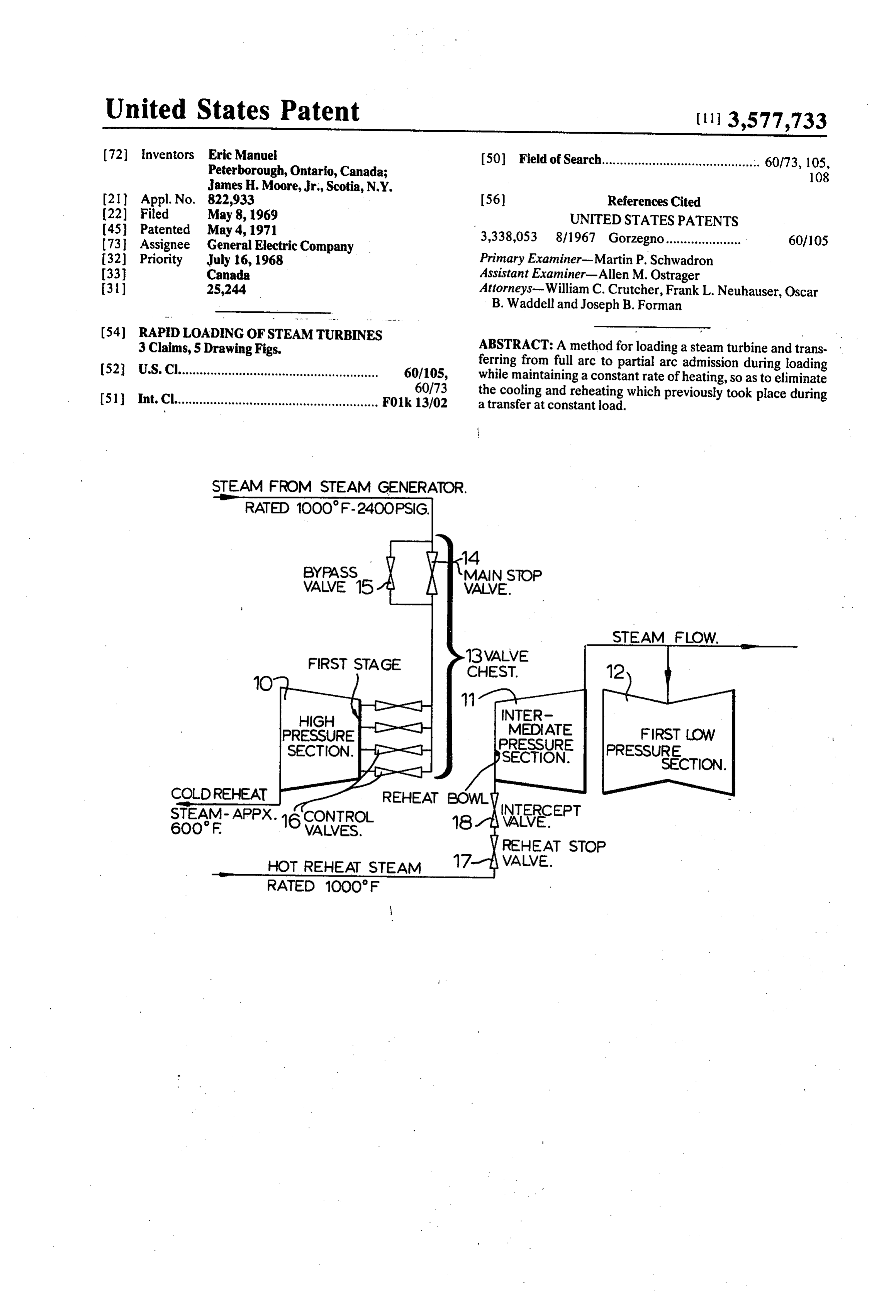
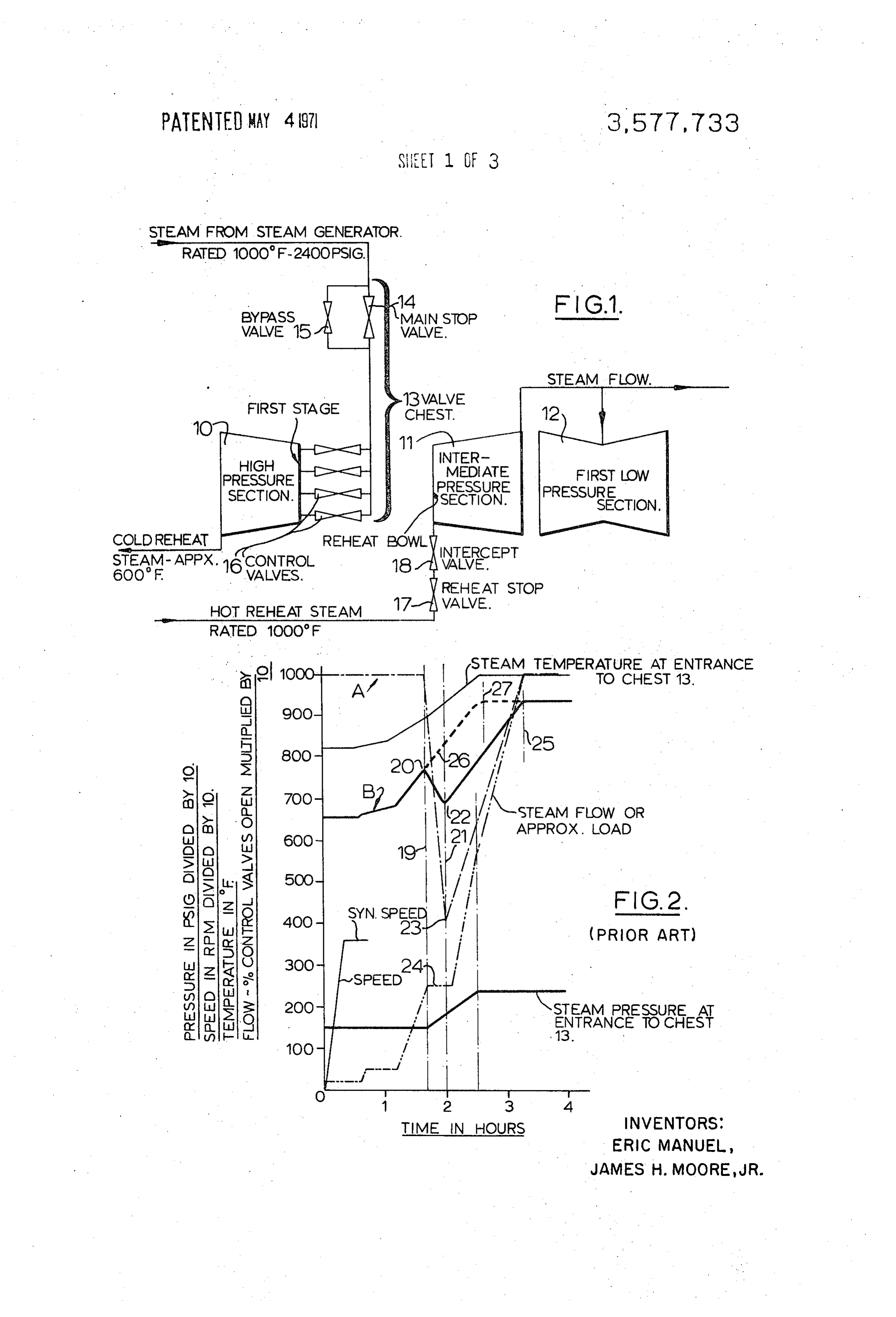
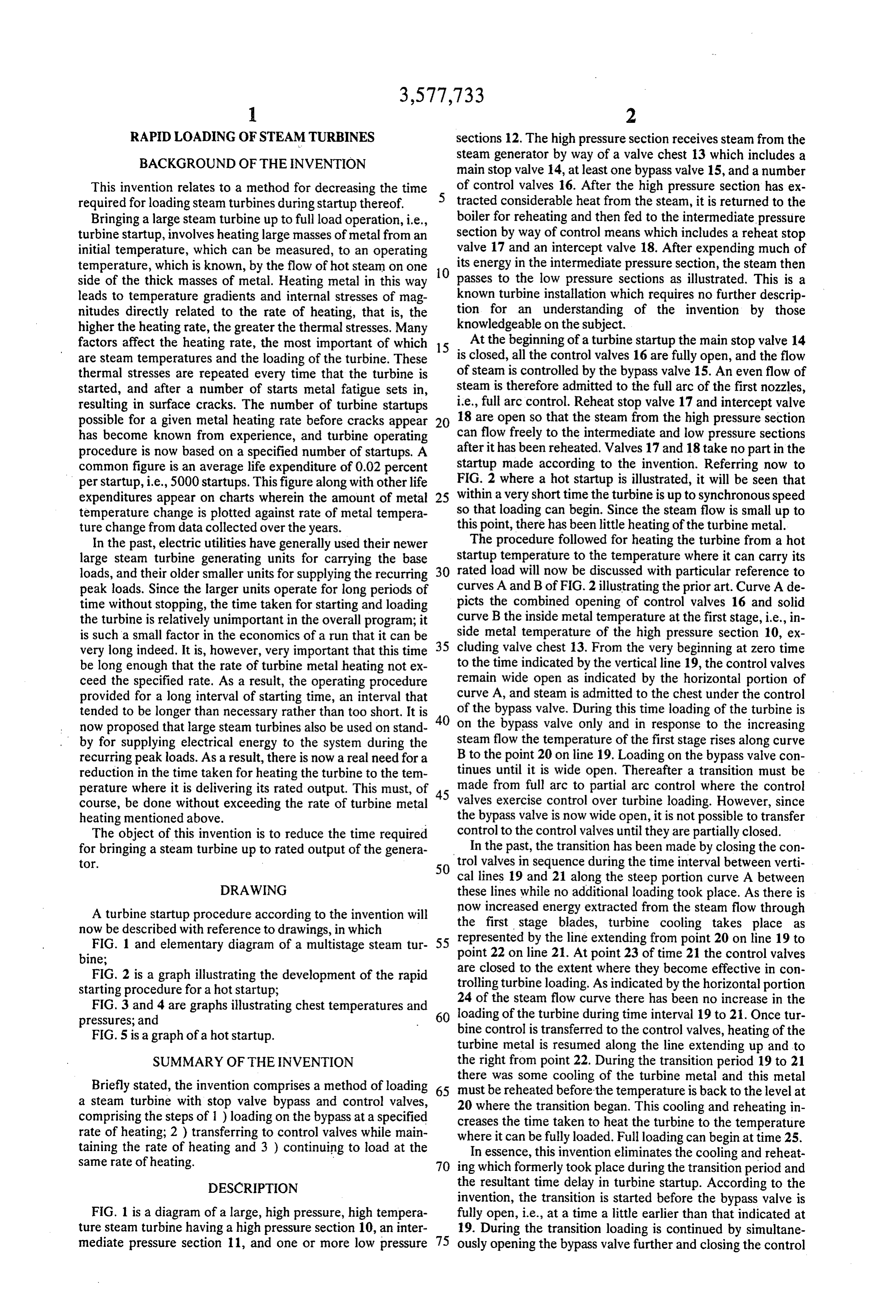
RAPIDLOADING OF STEAM TURBINES sections 12. The high pressure section receives steam from the BACKGROUND OF THE INVENTION steam generator by way of a valve chest 13 which includes a main stop valve 14, at least one bypass valve 15, and a number
This invention relates to a method for decreasing the time of control valves 16. After the high pressure section has ex required for loading steam turbines during startup thereof. tracted considerable heat from the steam, it is returned to the Bringing a large steam turbine up to full load operation, i.e., boiler for reheating and then fed to the intermediate pressure turbine startup, involves heating large masses of metal from an section by way of control means which includes a reheat stop initial temperature, which can be measured, to an operating valve 17 and an intercept valve 18. After expending much of temperature, which is known, by the flow of hot steam on one O its energy in the intermediate pressure section, the steam then side of the thick masses of metal. Heating metal in this way passes to the low pressure sections as illustrated. This is a leads to temperature gradients and internal stresses of mag known turbine installation which requires no further descrip nitudes directly related to the rate of heating, that is, the tion for an understanding of the invention by those higher the heating rate, the greater the thermal stresses. Many knowledgeable on the subject.
factors affect the heating rate, the most important of which 15 At the beginning of a turbine startup the main stop valve 14 are steam temperatures and the loading of the turbine. These is closed, all the control valves 16 are fully open, and the flow thermal stresses are repeated every time that the turbine is of steam is controlled by the bypass valve 15. An even flow of started, and after a number of starts metal fatigue sets in, steam is therefore admitted to the full arc of the first nozzles, resulting in surface cracks. The number of turbine startups i.e., full arc control. Reheat stop valve 17 and intercept valve possible for a given metal heating rate before cracks appear 20 18 are open so that the steam from the high pressure section has become known from experience, and turbine operating can flow freely to the intermediate and low pressure sections procedure is now based on a specified number of startups. A after it has been reheated. Valves 17 and 18 take no part in the common figure is an average life expenditure of 0.02 percent startup made according to the invention. Referring now to per startup, i.e., 5000 startups. This figure along with other life FIG. 2 where a hot startup is illustrated, it will be seen that expenditures appear on charts wherein the amount of metal 25 within a very short time the turbine is up to synchronous speed temperature change is plotted against rate of metal tempera so that loading can begin. Since the steam flow is small up to ture change from data collected over the years. this point, there has been little heating of the turbine metal. In the past, electric utilities have generally used their newer The procedure followed for heating the turbine from a hot large steam turbine generating units for carrying the base startup temperature to the temperature where it can carry its loads, and their older smaller units for supplying the recurring 30 rated load will now be discussed with particular reference to peak loads. Since the larger units operate for long periods of curves A and B of FIG. 2 illustrating the prior art. Curve A de time without stopping, the time taken for starting and loading picts the combined opening of control valves 16 and solid the turbine is relatively unimportant in the overall program; it curve B the inside metal temperature at the first stage, i.e., in is such a small factor in the economics of a run that it can be side metal temperature of the high pressure section 10, ex very long indeed. It is, however, very important that this time 35 cluding valve chest 13. From the very beginning at zero time be long enough that the rate of turbine metal heating not ex to the time indicated by the vertical line 19, the control valves ceed the specified rate. As a result, the operating procedure remain wide open as indicated by the horizontal portion of provided for a long interval of starting time, an interval that curve A, and steam is admitted to the chest under the control tended to be longer than necessary rather than too short. It is 40 of the bypass valve. During this time loading of the turbine is now proposed that large steam turbines also be used on stand on the bypass valve only and in response to the increasing by for supplying electrical energy to the system during the steam flow the temperature of the first stage rises along curve recurring peak loads. As a result, there is now a real need for a B to the point 20 on line 19. Loading on the bypass valve con reduction in the time taken for heating the turbine to the tem tinues until it is wide open. Thereafter a transition must be perature where it is delivering its rated output. This must, of 45 made from full arc to partial arc control where the control course, be done without exceeding the rate of turbine metal valves exercise control over turbine loading. However, since heating mentioned above. the bypass valve is now wide open, it is not possible to transfer The object of this invention is to reduce the time required control to the control valves until they are partially closed. for bringing a steam turbine up to rated output of the genera In the past, the transition has been made by closing the con tor. 50 trol valves in sequence during the time interval between verti cal lines 19 and 21 along the steep portion curve A between
DRAWING these lines while no additional loading took place. As there is A turbine startup procedure according to the invention will the now increased energy extracted from the steam flow through now be described with reference to drawings, in which first stage blades, turbine cooling takes place as FIG. 1 and elementary diagram of a multistage steam tur 55 point represented by the line extending from point 20 on line 19 to bine; 22 on line 21. At point 23 of time 21 the control valves are closed to the extent where they become effective in con
FIG. 2 is a graph illustrating the development of the rapid trolling starting procedure for a hot startup, turbine loading. As indicated by the horizontal portion 24 of the steam flow curve there has been no increase in the
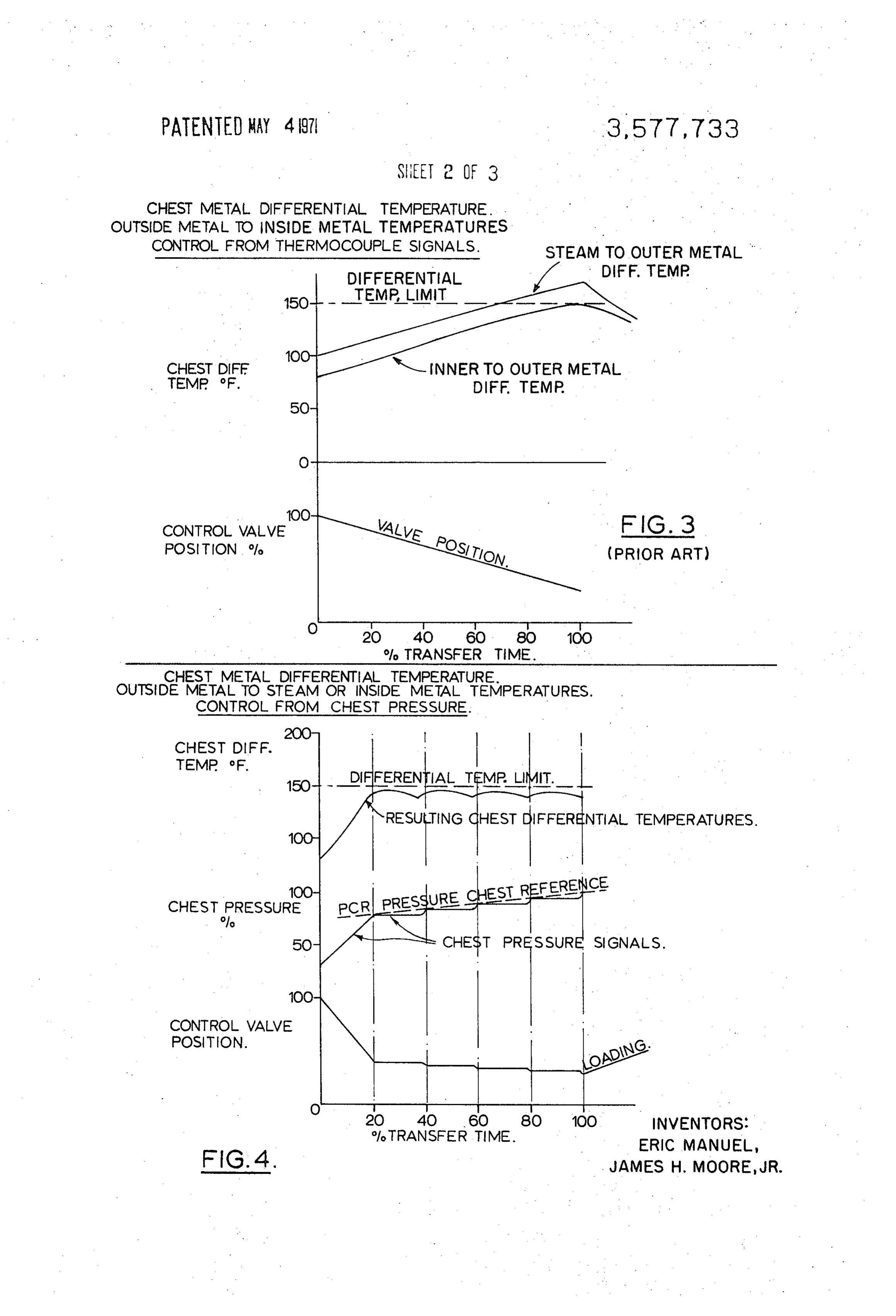
FIG.3 and 4 are graphs illustrating chest temperatures and loading of the turbine during time interval 19 to 21. Once tur pressures; and 60
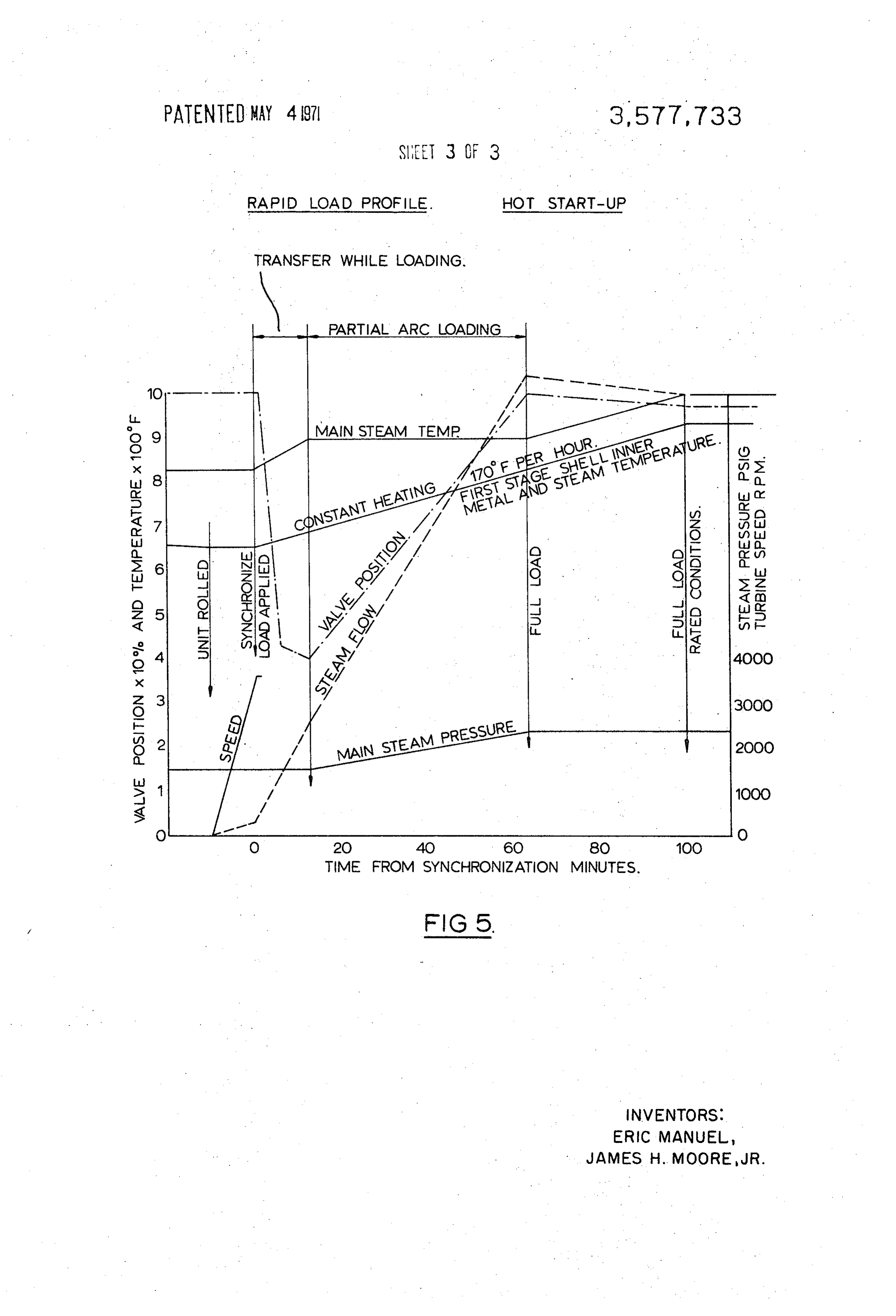
FIG. 5 is a graph of a hot startup. bine control is transferred to the control valves, heating of the turbine metal is resumed along the line extending up and to
SUMMARY OF THE INVENTION the right from point 22. During the transition period 19 to 21 Briefly stated, the invention comprises a method of loading 65 there was some cooling of the turbine metal and this metal must be reheated before the temperature is back to the level at a steam turbine with stop valve bypass and control valves, 20 where the transition began. This cooling and reheating in comprising the steps of 1) loading on the bypass at a specified creases the time taken to heat the turbine to the temperature rate of heating; 2) transferring to control valves while main taining the rate of heating and 3) continuing to load at the where In it can be fully loaded. Full loading can begin at time 25.
essence, this invention eliminates the cooling and reheat same rate of heating. 70 ing which formerly took place during the transition period and DESCRIPTION the resultant time delay in turbine startup. According to the invention, the transition is started before the bypass valve is
FIG. 1 is a diagram of a large, high pressure, high tempera fully open, i.e., at a time a little earlier than that indicated at ture steam turbine having a high pressure section 10, an inter 19. During the transition loading is continued by simultane mediate pressure section 11, and one or more low pressure 75 ously opening the bypass valve further and closing the control
Page 6
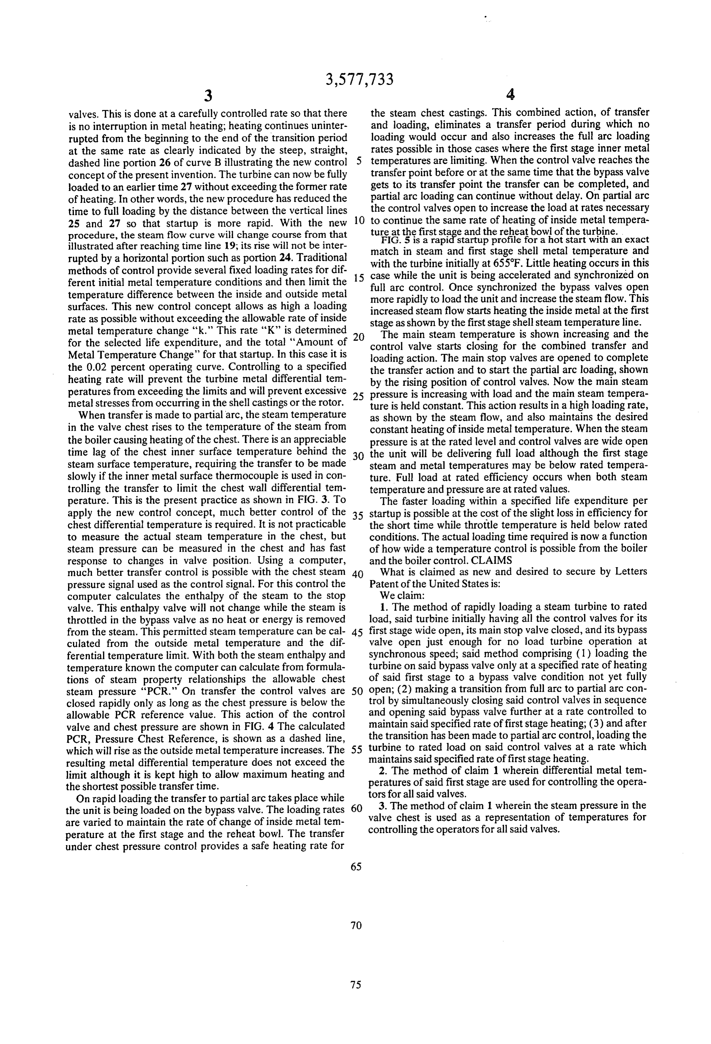
valves. This is done at a carefully controlled rate so that there the steam chest castings. This combined action, of transfer is no interruption in metal heating; heating continues uninter and loading, eliminates a transfer period during which no rupted from the beginning to the end of the transition period loading would occur and also increases the full arc loading at the same rate as clearly indicated by the steep, straight, rates possible in those cases where the first stage inner metal dashed line portion 26 of curve B illustrating the new control temperatures are limiting. When the control valve reaches the concept of the present invention. The turbine can now be fully transfer point before or at the same time that the bypass valve loaded to an earlier time 27 without exceeding the former rate gets to its transfer point the transfer can be completed, and of heating. In other words, the new procedure has reduced the partial arc loading can continue without delay. On partial arc time to full loading by the distance between the vertical lines 10 the control valves open to increase the load at rates necessary 25 and 27 so that startup is more rapid. With the new to continue the same rate of heating of inside metal tempera procedure, the steam flow curve will change course from that tureFIG.
at the 5 isfirst stagestartup a rapid and theprofile reheatforbowl of start a hot the turbine.
with an exact illustrated after reaching time line 19; its rise will not be inter rupted by a horizontal portion such as portion 24. Traditional with the turbine initially at 655°F. Little heating occurs in and match in steam and first stage shell metal temperature methods of control provide several fixed loading rates for dif 15 case while the unit is being accelerated and synchronizedthis on ferent initial metal temperature conditions and then limit the full arc control. Once synchronized the bypass valves open temperature difference between the inside and outside metal surfaces. This new control concept allows as high a loading more rapidly to load the unit and increase the steam flow. This increased steam flow starts heating the inside metal at the first rate as possible without exceeding the allowable rate of inside stage as shown by the first stage shell steam temperature line. metal temperature change “k." This rate "K" is determined 20 The main steam temperature is shown increasing and the for the selected life expenditure, and the total "Amount of control valve starts closing for the combined transfer and Metal Temperature Change" for that startup. In this case it is loading action. The main stop valves are opened to complete the 0.02 percent operating curve. Controlling to a specified the transfer action and to start the partial arc loading, shown heating rate will prevent the turbine metal differential tem by the rising position of control valves. Now the main steam peratures from exceeding the limits and will prevent excessive 25 pressure is increasing with load and the main steam tempera metal stresses from occurring in the shell castings or the rotor. ture is held constant. This action results in a high loading rate, When transfer is made to partial arc, the steam temperature as shown by the steam flow, and also maintains the desired in the valve chest rises to the temperature of the steam from constant heating of inside metal temperature. When the steam the boiler causing heating of the chest. There is an appreciable pressure is at the rated level and control valves are wide open time lag of the chest inner surface temperature behind the 30 the unit will be delivering full load although the first stage steam surface temperature, requiring the transfer to be made steam and metal temperatures may be below rated tempera slowly if the inner metal surface thermocouple is used in con ture. Full load at rated efficiency occurs when both steam trolling the transfer to limit the chest wall differential tem temperature and pressure are at rated values. perature. This is the present practice as shown in FIG. 3. To The faster loading within a specified life expenditure per apply the new control concept, much better control of the 35 startup is possible at the cost of the slight loss in efficiency for chest differential temperature is required. It is not practicable the short time while throttle temperature is held below rated to measure the actual steam temperature in the chest, but conditions. The actual loading time required is now a function steam pressure can be measured in the chest and has fast of how wide a temperature control is possible from the boiler response to changes in valve position. Using a computer, and the boiler control. CLAIMS much better transfer control is possible with the chest steam 40 What is claimed as new and desired to secure by Letters pressure signal used as the control signal. For this control the Patent of the United States is:
computer calculates the enthalpy of the steam to the stop We claim:
valve. This enthalpy valve will not change while the steam is 1. The method of rapidly loading a steam turbine to rated throttled in the bypass valve as no heat or energy is removed load, said turbine initially having all the control valves for its from the steam. This permitted steam temperature can be cal 45 first stage wide open, its main stop valve closed, and its bypass culated from the outside metal temperature and the dif valve open just enough for no load turbine operation at ferential temperature limit. With both the steam enthalpy and synchronous speed; said method comprising (1) loading the temperature known the computer can calculate from formula turbine on said bypass valve only at a specified rate of heating tions of steam property relationships the allowable chest of said first stage to a bypass valve condition not yet fully steam pressure "PCR." On transfer the control valves are 50 open; (2) making a transition from full arc to partial arc con closed rapidly only as long as the chest pressure is below the trol by simultaneously closing said control valves in sequence allowable PCR reference value. This action of the control and opening said bypass valve further at a rate controlled to valve and chest pressure are shown in FIG. 4 The calculated maintain said specified rate of first stage heating; (3) and after PCR, Pressure Chest Reference, is shown as a dashed line, the transition has been made to partial arc control, loading the which will rise as the outside metal temperature increases. The 55 turbine to rated load on said control valves at a rate which resulting metal differential temperature does not exceed the maintains said specified rate of first stage heating. 2. The method of claim 1 wherein differential metal tem limit although it is kept high to allow maximum heating and peratures of said first stage are used for controlling the opera the shortest possible transfer time. tors for all said valves.
On rapid loading the transfer to partial arc takes place while 3. The method of claim 1 wherein the steam pressure in the the unit is being loaded on the bypass valve. The loading rates 60 valve are varied to maintain the rate of change of inside metal tem chest is used as a representation of temperatures for perature at the first stage and the reheat bowl. The transfer controlling the operators for all said valves. under chest pressure control provides a safe heating rate for
Provenance
- Collection
- Cited prior art
- Original PDF
- patentimages.storage.googleapis.com →
- Filed
- 1969-05-08
- Pages
- 6
- Method
- pdftotext (the PDF's own text layer) + pdftoppm 300dpi page scans
- Source
- Google Patents bibliographic record
- Granted
- 1971-05-04
- Inventors
- Eric Manuel; James H Moore Jr; General Electric Co
- Transcribed from
- patentimages.storage.googleapis.com →