patent · US6113865
Reactor configuration for a liquid gasification process
5 September 2000
Page 1 — bibliographic record
United States Patent (19) 11 Patent Number: 6,113,865 Dammann et al. (45) Date of Patent: Sep. 5, 2000 54 REACTOR CONFIGURATION FOR A Attorney, Agent, or Firm-Koley Jessen P.C.; Mark D. LIQUID GASIFICATION PROCESS Frederiksen
76 Inventors: Wilbur A. Dammann, 1115 Carriage 57 ABSTRACT Rd., Papillion, Nebr. 68046; W. David
Wallman, 1350 Northface Ct., Colorado The reactor configuration for a liquid gasification process Springs, Colo. 80919 includes an apparatus for liquid gasification Such as that described in U.S. Pat. No. 5,159,900. Included in the appa 21 Appl. No.: 09/244,602 ratus for liquid gasification are a reaction chamber at least partially filled with liquid, a pair of electrodes, and means 22 Filed: Feb. 4, 1999 for creating an electrical arc between the electrodes. When the electrical arc is Struck, carbon in the reaction chamber is
Related U.S. Application Data ionized and vaporized while energy is dissipated in the form 60 Provisional application No. 60/073,818, Feb. 5, 1998. of high intensity light radiation. Electrons pass though the (51) Int. Cl. ................................................ B01J 19/08 Vaporized carbon, causing the carbon vapor to oxidize or 52 U.S. Cl. ......................................................... 422/186.21 burn releasing COH gas. The displacement of oxygen in the 58 Field of Search ....................... 422/186.21; 204/164, liquid by forced rapid oxidation is an endothermic reaction. 204/172 The electrodes are spaced-apart So that the arc is located generally in the center of the reaction chamber. The interior 56) References Cited of the reaction chamber is generally Spherical in shape and
Optionally, the reaction chamber is preSSurized to further 5,159,900 11/1992 Dammann ................................... 123/3 enhance the efficiency of the reaction. 5,417,817 5/1995 Dammann et al. ..................... 204/129
Primary Examiner Kishor Mayekar 6 Claims, 3 Drawing Sheets
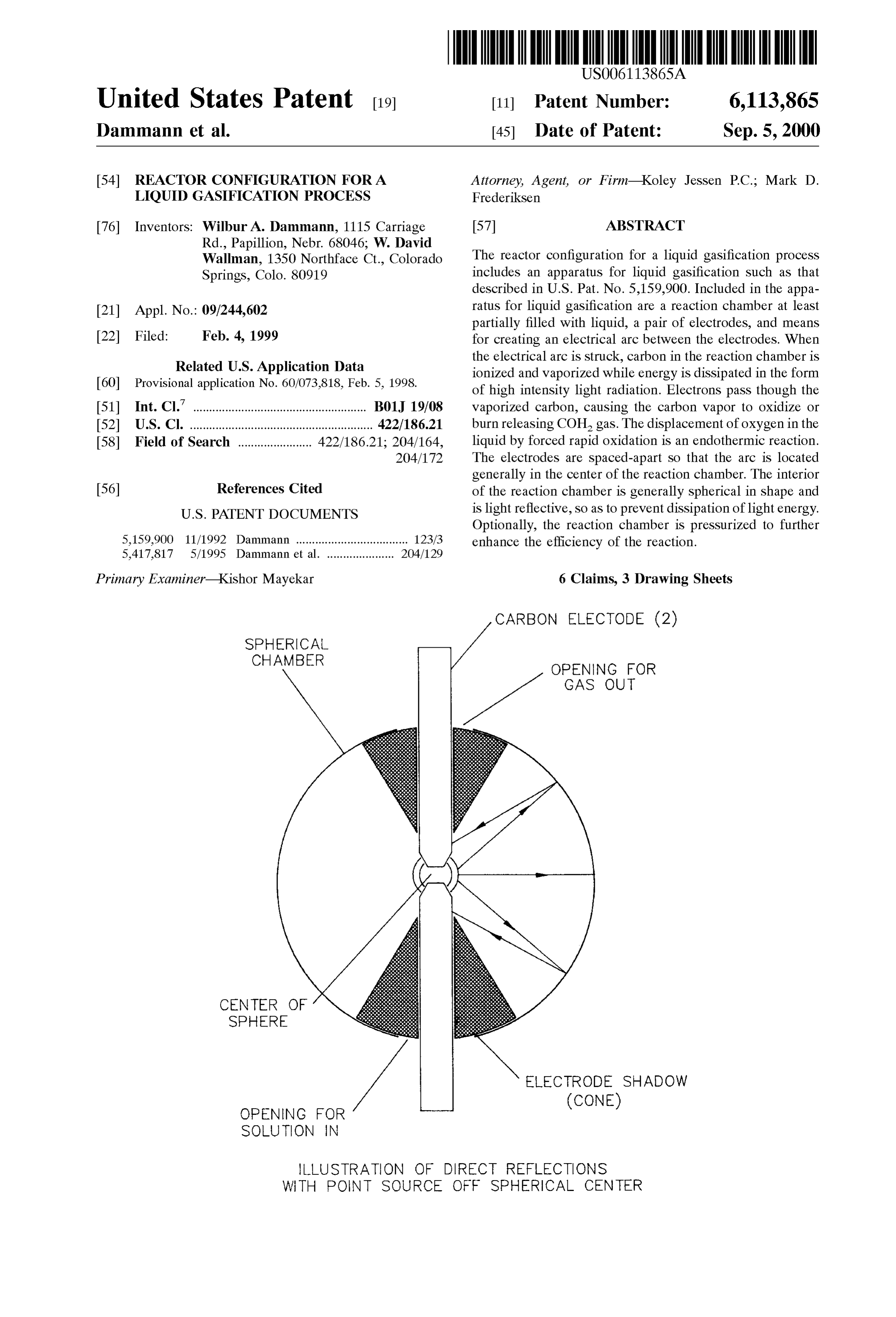
CARBON ELECTODE (2)
SPHERICAL
CHAMBER
OPENING FOR
GAS OUT
CENTER OF
SPHERE
ELECTRODE SHADOW
OPENING FOR
(CONE)
SOLUTION IN
LLUSTRATION OF DIRECT REFLECTIONS
WITH POINT SOURCE OFF SPHERICAL CENTER
Page 2
Drawing sheet — no readable text.
Page 3
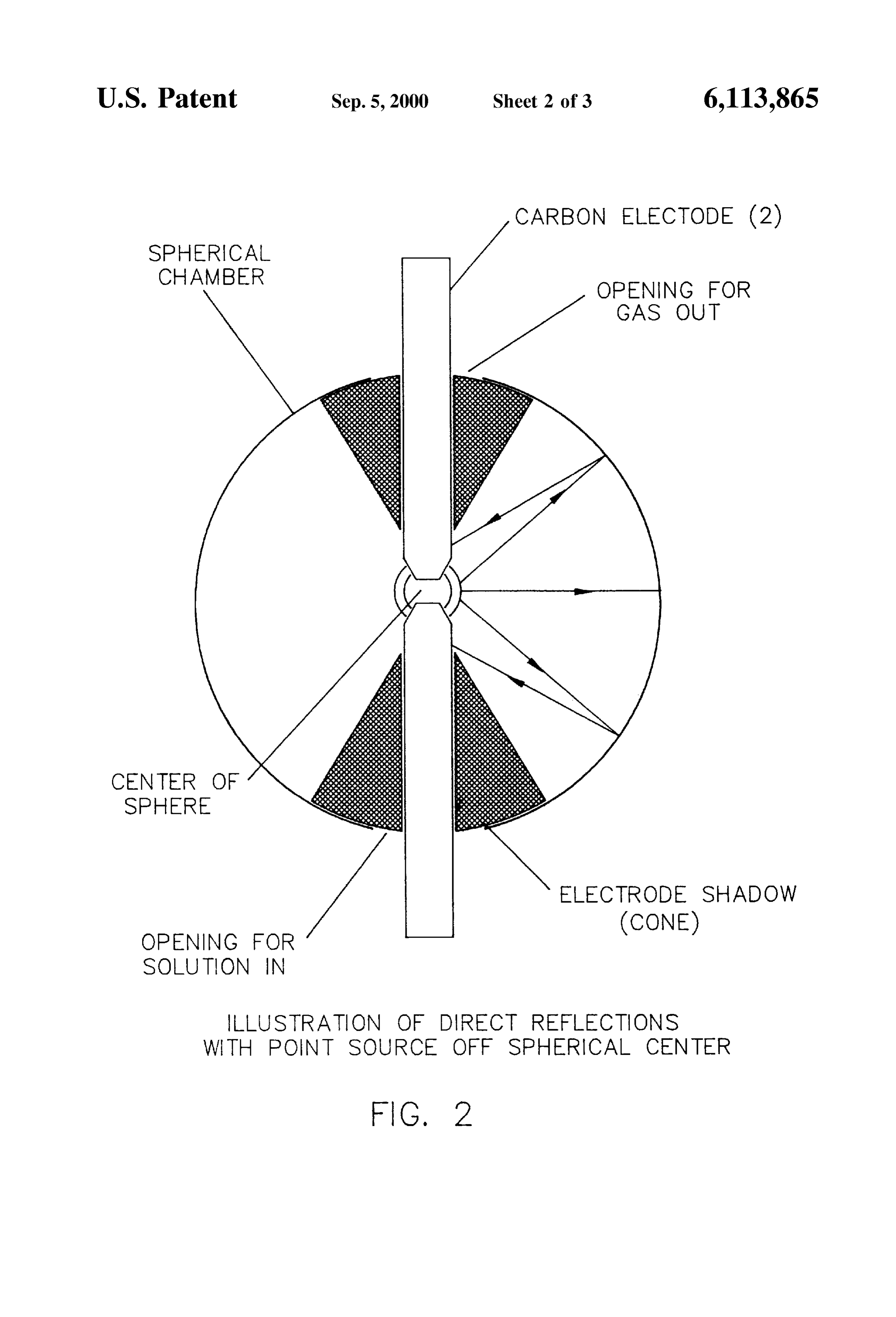
.S. Patent Sep. 5, 2000 Sheet 2 of 3 6,113,865
CARBON ELECTODE (2)
SPHERICAL
GAS OUT
CENTER OF
SPHERE
ELECTRODE SHADOW
OPENING FOR
(CONE)
SOLUTION N
LLUSTRATION OF DIRECT REFLECTIONS
WITH PONT SOURCE OFF SPHERICAL CENTER
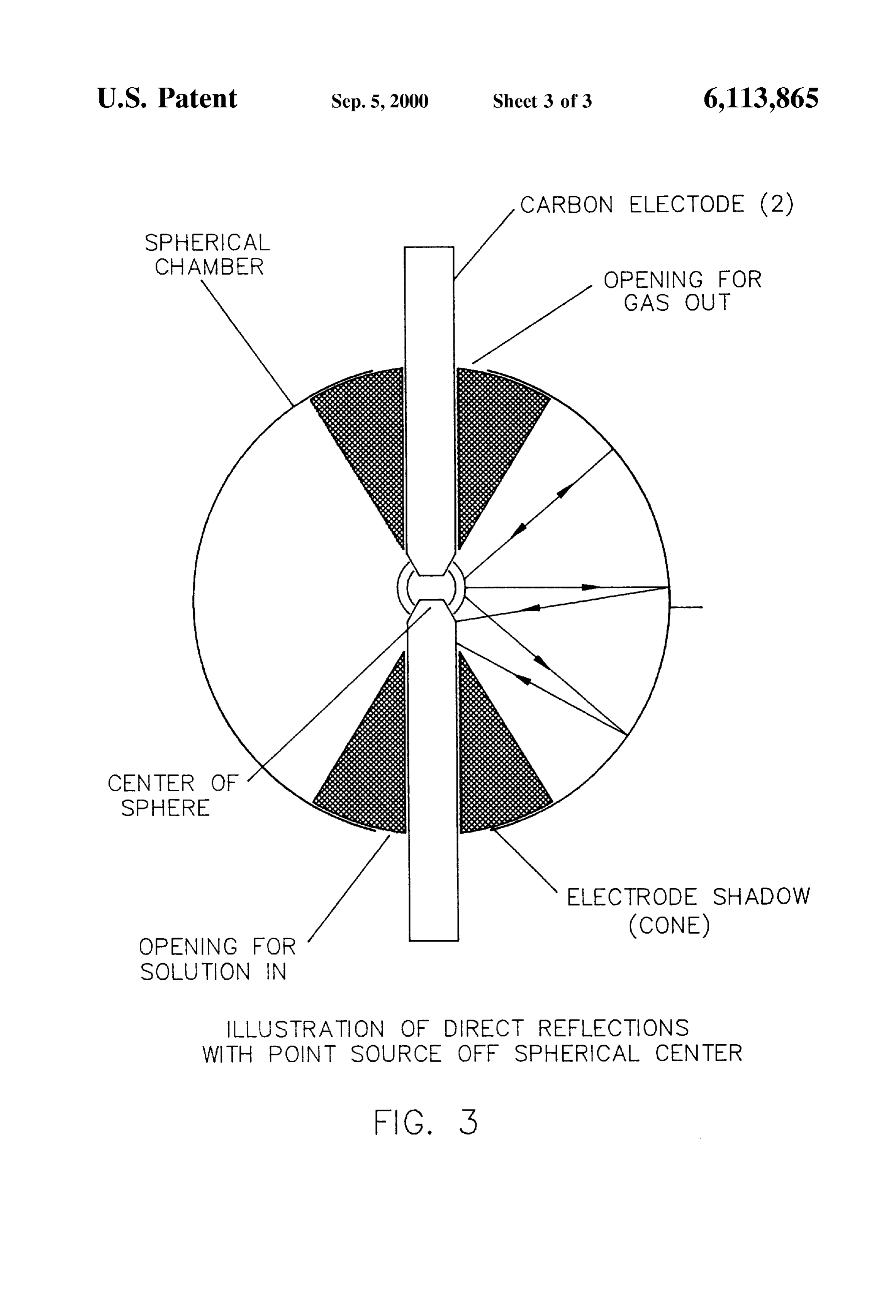
Page 4
ARBON ELECTODE (2)
SPHERICAL
GAS OUT
CENTER OF
SPHERE
ELECTRODE SHADOW
OPENING FOR
(CONE)
SOLUTION IN
LLUSTRATION OF DIRECT REFLECTIONS
WITH POINT SOURCE OFF SPHERICAL CENTER
Page 5
REACTOR CONFIGURATION FOR A process which enhances the efficiency of the electrothermal LIQUID GASIFICATION PROCESS chemical reaction.
CROSS-REFERENCE TO RELATED Another object of the invention is to provide a reaction chamber which is reflective.
APPLICATION
Still another object of the invention is to provide a
Applicants filed a provisional application as a Small entity reflective reaction chamber which is generally Spherical in entitled “REACTOR CONFIGURATION FOR BIOMASS shape.
GASIFICATION PROCESS’’ which was accorded Ser. No. Another object of the invention is to provide a pressurized 60/073,818 and a filing date of Feb. 5, 1998. reaction chamber.
TECHNICAL FIELD These and other objects will be apparent to those skilled in the art.
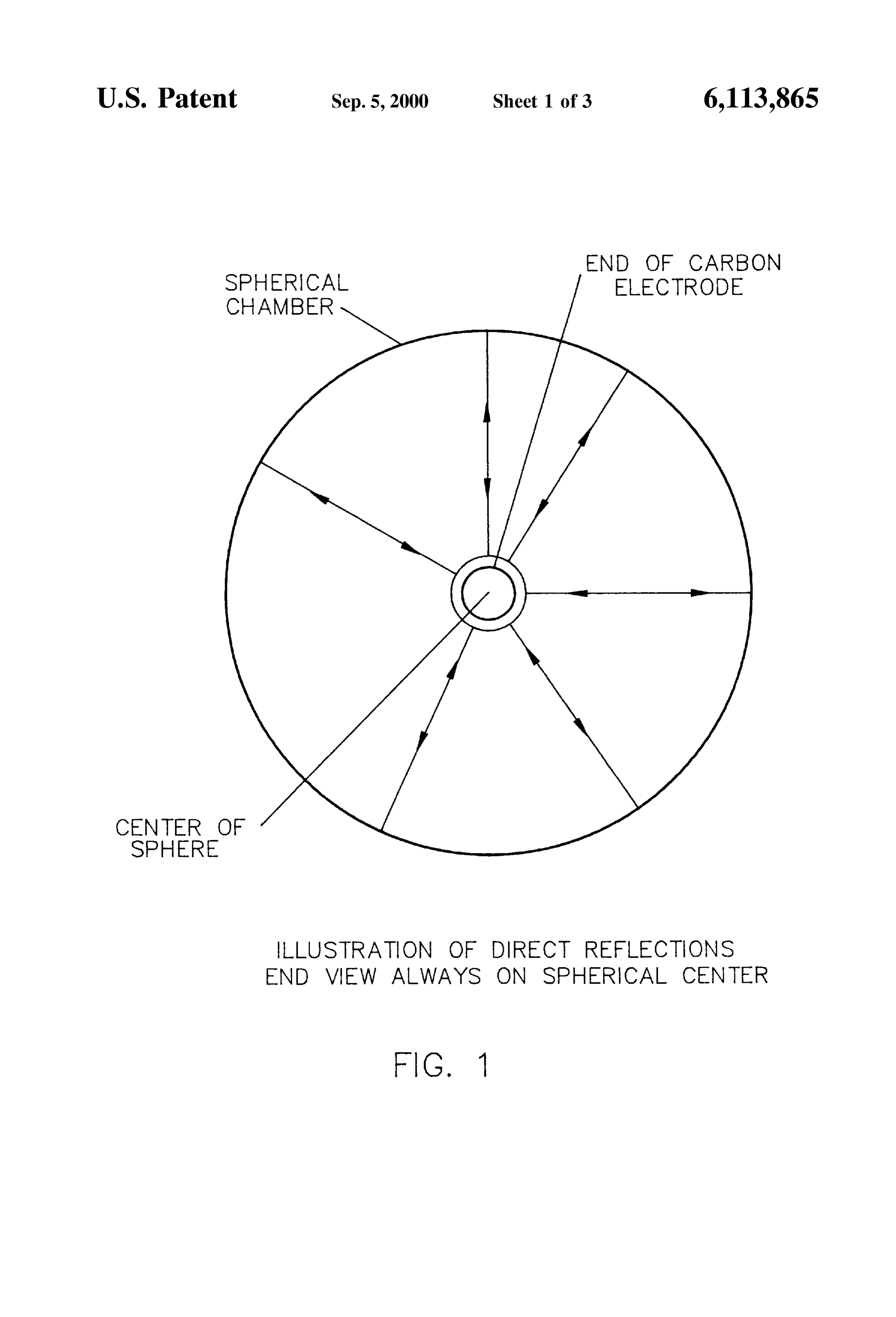
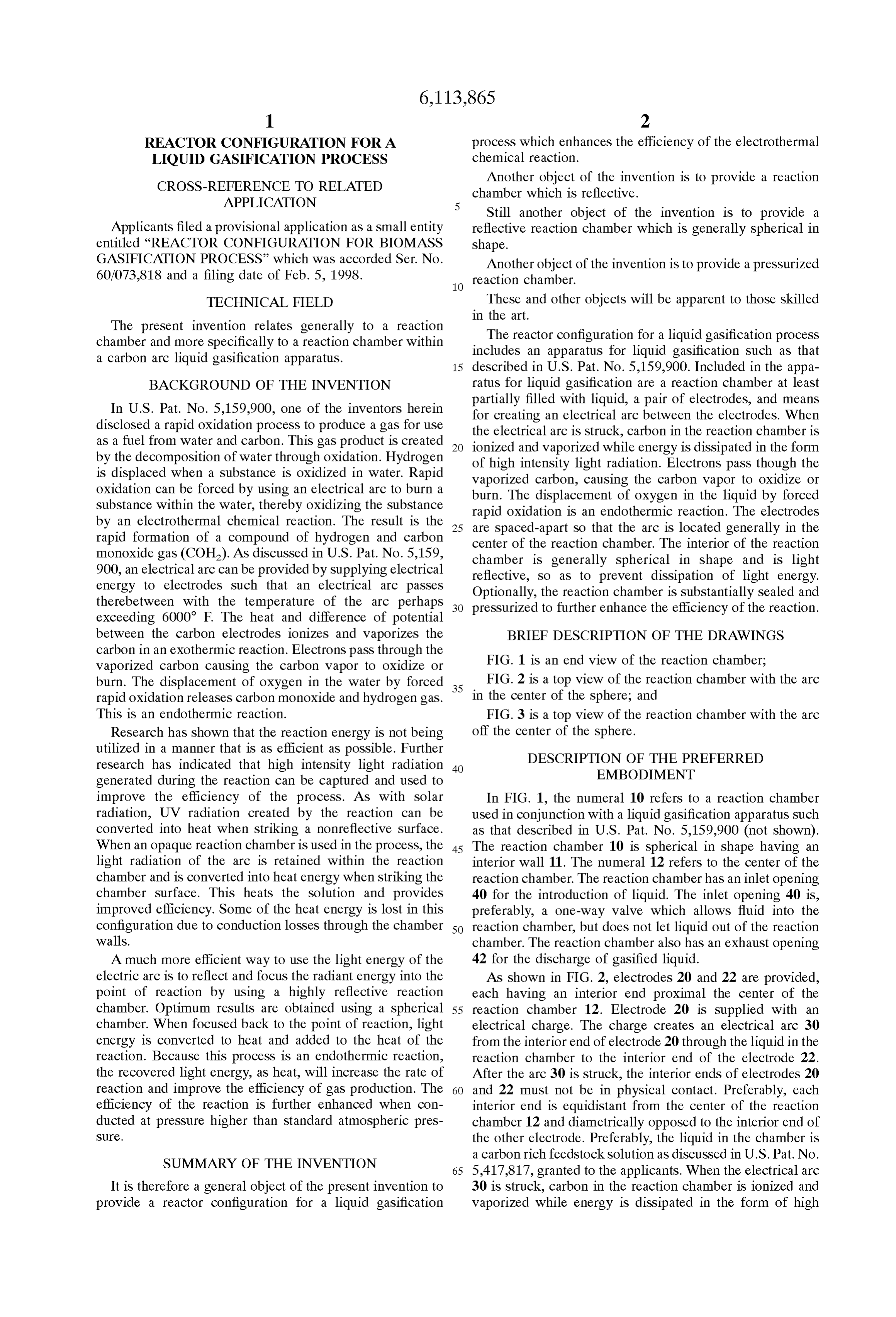
The present invention relates generally to a reaction The reactor configuration for a liquid gasification process chamber and more specifically to a reaction chamber within includes an apparatus for liquid gasification Such as that a carbon arc liquid gasification apparatus. 15 described in U.S. Pat. No. 5,159,900. Included in the appa BACKGROUND OF THE INVENTION ratus for liquid gasification are a reaction chamber at least partially filled with liquid, a pair of electrodes, and means
In U.S. Pat. No. 5,159,900, one of the inventors herein disclosed a rapid oxidation process to produce a gas for use for creating an electrical arc between the electrodes. When the electrical arc is Struck, carbon in the reaction chamber is as a fuel from water and carbon. This gas product is created by the decomposition of water through oxidation. Hydrogen ionized and vaporized while energy is dissipated in the form of high intensity light radiation. Electrons pass though the is displaced when a Substance is oxidized in water. Rapid Vaporized carbon, causing the carbon vapor to oxidize or oxidation can be forced by using an electrical arc to burn a burn. The displacement of oxygen in the liquid by forced Substance within the water, thereby oxidizing the Substance by an electrothermal chemical reaction. The result is the 25 rapid are oxidation is an endothermic reaction. The electrodes spaced-apart So that the arc is located generally in the rapid formation of a compound of hydrogen and carbon center of the reaction chamber. The interior of the reaction monoxide gas (COH). As discussed in U.S. Pat. No. 5,159, chamber is generally Spherical in Shape and is light 900, an electrical arc can be provided by Supplying electrical reflective, So as to prevent dissipation of light energy. energy to electrodes Such that an electrical arc passes Optionally, the reaction chamber is Substantially Sealed and therebetween with the temperature of the arc perhaps exceeding 6000 F. The heat and difference of potential preSSurized to further enhance the efficiency of the reaction. between the carbon electrodes ionizes and vaporizes the BRIEF DESCRIPTION OF THE DRAWINGS carbon in an exothermic reaction. Electrons pass through the
Vaporized carbon causing the carbon vapor to oxidize or FIG. 1 is an end view of the reaction chamber; burn. The displacement of oxygen in the water by forced 35 FIG. 2 is a top view of the reaction chamber with the arc rapid oxidation releases carbon monoxide and hydrogen gas. in the center of the Sphere; and
This is an endothermic reaction. FIG. 3 is a top view of the reaction chamber with the arc Research has shown that the reaction energy is not being off the center of the sphere.
utilized in a manner that is as efficient as possible. Further DESCRIPTION OF THE PREFERRED research has indicated that high intensity light radiation 40 EMBODIMENT generated during the reaction can be captured and used to improve the efficiency of the process. AS with Solar In FIG. 1, the numeral 10 refers to a reaction chamber radiation, UV radiation created by the reaction can be used in conjunction with a liquid gasification apparatuS Such converted into heat when Striking a nonreflective Surface. as that described in U.S. Pat. No. 5,159,900 (not shown). When an opaque reaction chamber is used in the process, the 45 The reaction chamber 10 is spherical in Shape having an light radiation of the arc is retained within the reaction interior wall 11. The numeral 12 refers to the center of the chamber and is converted into heat energy when Striking the reaction chamber. The reaction chamber has an inlet opening chamber Surface. This heats the Solution and provides 40 for the introduction of liquid. The inlet opening 40 is, improved efficiency. Some of the heat energy is lost in this preferably, a one-way valve which allows fluid into the configuration due to conduction losses through the chamber 50 reaction chamber, but does not let liquid out of the reaction walls. chamber. The reaction chamber also has an exhaust opening A much more efficient way to use the light energy of the 42 for the discharge of gasified liquid.
electric arc is to reflect and focus the radiant energy into the As shown in FIG. 2, electrodes 20 and 22 are provided, point of reaction by using a highly reflective reaction each having an interior end proximal the center of the chamber. Optimum results are obtained using a spherical 55 reaction chamber 12. Electrode 20 is supplied with an chamber. When focused back to the point of reaction, light electrical charge. The charge creates an electrical arc 30 energy is converted to heat and added to the heat of the from the interior end of electrode 20 through the liquid in the reaction. Because this process is an endothermic reaction, reaction chamber to the interior end of the electrode 22. the recovered light energy, as heat, will increase the rate of After the arc 30 is struck, the interior ends of electrodes 20 reaction and improve the efficiency of gas production. The 60 and 22 must not be in physical contact. Preferably, each efficiency of the reaction is further enhanced when con interior end is equidistant from the center of the reaction ducted at pressure higher than Standard atmospheric pres chamber 12 and diametrically opposed to the interior end of SUC. the other electrode. Preferably, the liquid in the chamber is a carbon rich feedstock Solution as discussed in U.S. Pat. No.
SUMMARY OF THE INVENTION 65 5,417,817, granted to the applicants. When the electrical arc It is therefore a general object of the present invention to 30 is struck, carbon in the reaction chamber is ionized and provide a reactor configuration for a liquid gasification Vaporized while energy is dissipated in the form of high
Page 6
intensity light radiation. Electrons pass though the vaporized We claim:
carbon, causing the carbon vapor to oxidize or burn. The 1. A reactor for a liquid gasification process, comprising: displacement of oxygen in the liquid by forced rapid oxi dation is an endothermic reaction. a reaction chamber having a reflecting interior Surface and In the reaction chamber 10 of the present invention, high adapted to be at least partially filled with liquid; intensity light radiation caused by the electrical arc 30 a pair of Spaced-apart carbon electrodes disposed in Said travels one of two possible paths. The first possible path of reaction chamber and adapted to be immersed in the travel of the light within the reaction chamber 10 is opaque liquid;
and is directly from the electrical arc 30 to either electrode means for Supplying an electrical current to Said elec 20 or 22. The other possible path of travel is from the trodes to create an electrical arc between said elec electrical arc 30 to the interior wall 11 of the reaction chamber 10. The interior wall 11 of the reaction chamber 10 trodes.
is preferably reflective. If the arc 30 is generated at the center 2. The reactor of claim 1 wherein said reaction chamber of the reaction chamber 12 and the reaction chamber 10 is has a reflective interior Surface that is generally spherical, Spherical, light generated by the electrical arc 30 would 15 and has a center.
reflect off the interior wall 11 of the reaction chamber 10 to 3. The reactor of claim 2 in which the electric arc is the Site of carbon vapor oxidation. The paths of incidence located generally in Said center of Said reaction chamber. and reflection of light are designated by the numeral 14. If 4. A reactor for a liquid gasification process, comprising: the electrical arc 30 is generated in a position other than in a pressurized reaction chamber having a reflective interior the center of the reaction chamber 12, light generated by the Surface and adapted to be at least partially filled with electrical arc 30 is still reflected by the interior wall 11 of the liquid;
reaction chamber 10 along the paths of incidence and a pair of Spaced-apart carbon electrodes disposed in Said reflection 14 Such that energy is focused generally in the vicinity of carbon vapor oxidation. preSSurized reaction chamber and adapted to be Whether light generated by electrical arc 30 strikes either 25 immersed in the liquid;
of electrodes 20 or 22, or is reflected off the interior wall 11 means for Supplying an electrical current to Said elec of the reaction chamber 10 Such that it is focused in the trodes to create an electrical arc between said elec vicinity of the carbon vapor oxidation, the light energy is trodes.
converted to heat and added to the heat of the reaction. 5. The reactor of claim 4 wherein said pressurized reac Because the oxidation process involves an endothermic tion chamber has an interior Surface that is generally reaction, the recovered light energy, as heat, increases the Spherical, and has a center.
rate of reaction and improves the efficiency of gas produc 6. The reactor of claim 5 in which the electric arc is tion. The efficiency of the reaction is further enhanced when located generally in Said center of Said pressurized reaction the reaction chamber 10 is pressurized. 35 chamber.
Thus it can be seen that the invention accomplishes at least all of its Stated objectives.
Provenance
- Collection
- Cited prior art
- Original PDF
- patentimages.storage.googleapis.com →
- Filed
- 1999-02-04
- Pages
- 6
- Method
- pdftotext (the PDF's own text layer) + pdftoppm 300dpi page scans
- Source
- Google Patents bibliographic record
- Granted
- 2000-09-05
- Inventors
- Wilbur A. Dammann; W. David Wallman
- Transcribed from
- patentimages.storage.googleapis.com →