patent · US5628885
Extraction installation for hydrogen and oxygen
13 May 1997
Page 1 — bibliographic record
United States Patent 19 11 Patent Number: 5,628,885 Lin 45 Date of Patent: May 13, 1997 54 EXTRACTION INSTALLATION FOR 57 ABSTRACT
HYDROGEN AND OXYGEN
This electrolytic apparatus for a welding machine uses an 76) Inventor: Yang C. Lin, No. 3, Lane 13, Alley electrolytic cell, a mixing tank and a multi-control switch. 473, Nanta Road, Hsinchu, Taiwan The electrolytic cell is composed of several pieces of 21 Appl. No.: 555,020 electrode plates which are assembled in a row, the farthest side of which is connected to the positive and negative poles 22 Filed: Nov. 13, 1995 of electrolysis power. After electrolysis, the gas proceeds in (51 Int. Cl. ............. C25B 9/00; C25B 15/08 a storage tank and the liquid is guided back into the 52 U.S. Cl. .......................... 204/228; 204/237; 204/239; electrolytic cell for recycling use. The fuel gas then goes into 204/241; 204/270; 204/278; 204/268 a first chamber to get rid of water. In the meantime, part of 58) Field of Search .................................... 204/240,268, the fuel gas will be combined with carbohydrate dissolvent 204/269,270, 228, 237,274,278 to alterits fuel composition and then be recombined with the 56) References Cited rest of the gas to provide a desired fuel. This way, the heat of the gas can be heightened, flame temperature can be
lowered, and the output ratio for the fuel gas can be 3,957,618 5/1976 Spirig ...................................... 204/270 controlled and adjusted to attain a welding gun's flame 4,014,777 3/1977 Brown ..................................... 2041270 within a comprehensive scope of temperature and heat. 4,424,105 1/1984 Hanson ............. ... 204/27OX 4,457,816 7/1984 Galluzzo et al. ................... 2041270 X Furthermore, this invention uses the pressure from a multi 5,292,405 3/1994 Wicks ................................. 204/268 X control switch monitoring the process to keep it in a toler able range to provide safety protection.
Primary Examiner-Donald R. Valentine
Attorney, Agent, or Firm-Beveridge, DeGrandi, Weilacher & Young, L.L.P. 21 Claims, 10 Drawing Sheets
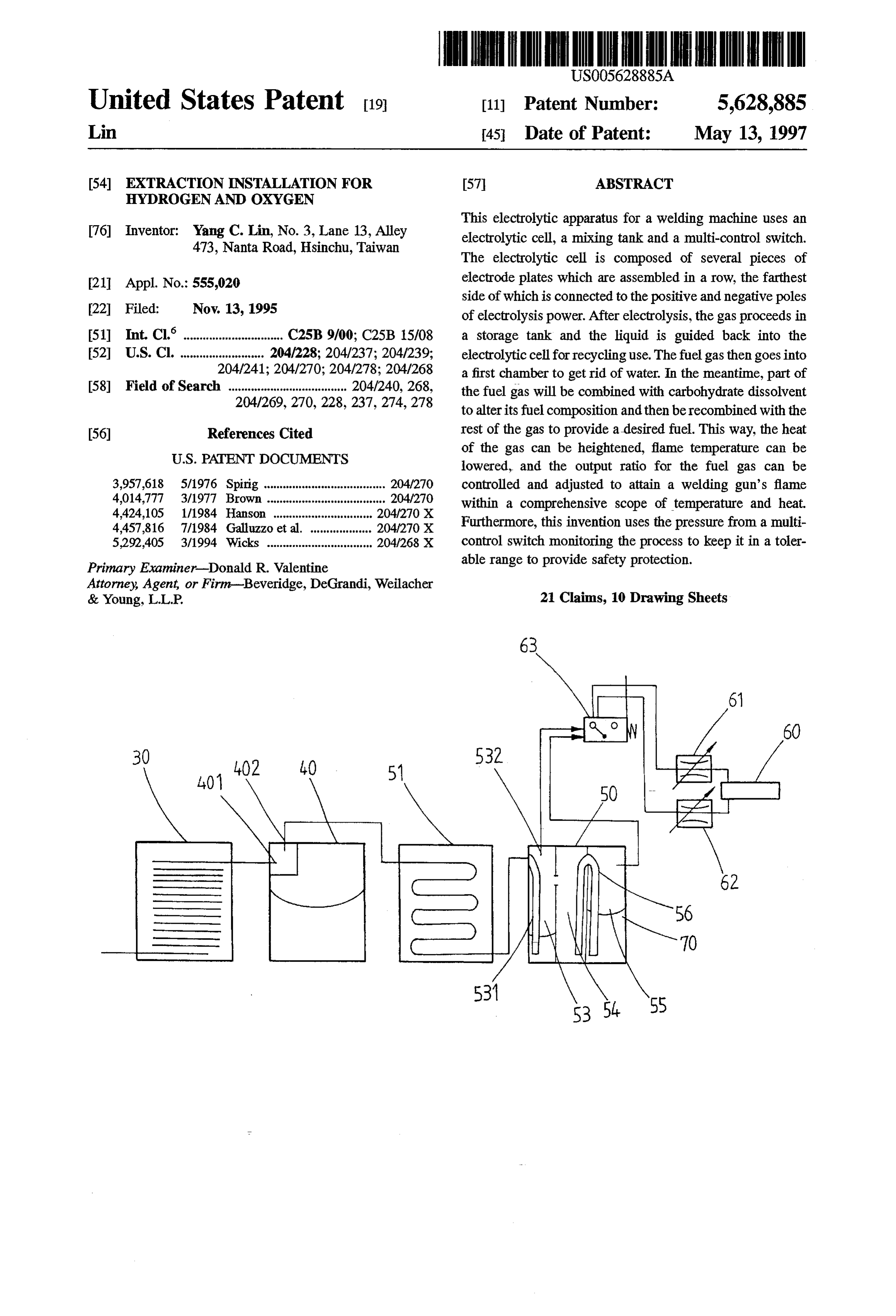
30 402 40 51 a l,01 50 4
Y An
Page 2
Drawing sheet — no readable text.
Page 3
Drawing sheet — no readable text.
Page 4
Drawing sheet — no readable text.
Page 5
Drawing sheet — no readable text.
Page 6
Drawing sheet — no readable text.
Page 7
Drawing sheet — no readable text.
Page 8
Drawing sheet — no readable text.
Page 9
Drawing sheet — no readable text.
Page 10
Drawing sheet — no readable text.
Page 11
Drawing sheet — no readable text.
Page 12
EXTRACTION INSTALLATION FOR mainly composed of electrolytic cell without cover, a mixing HYDROGENAND OXYGEN tankfor mixture of fuel composition in process and a set of multi-control switch with self-protection function. The elec
FIELD OF THE INVENTION trolytic cell is assembled by several pieces of electrode This invention relates to a sort of extraction installation 5 plates in a parallel row. Through electrode plates connected for hydrogen and oxygen which can be applied to oxy in series to equally share the voltage from electrolysis power, it is unnecessary to lower the voltage through trans hydrogen welding machine. Especially it specifies its func former and the current of commutator can be lowered so as tion of using a multi-pole partial pressure composition to equally share electrolysis voltage so as to the current needed O to the dimension and weight on the cover of the electrolytic can be attained. As well, use of a mixing tank to mix fuel Through cell can be minimized and effectiveness can be heightened. composition, the welding flame temperature of the welding the storage tank connected to the top of electrolytic machine can be adjusted. cell, the dispersed electrolysis liquid can be collected and re-input into the electrolytic cell for recycling use and the
BACKGROUND OF THE INVENTON temperature of the electrolytic cell can be controlled via 15 temperature controlling method within a specific range.
The industrial used oxy-hydrogen welding machine is to take advantage of mixed gas, which is generated from Through get rid water erasing chamberinside of the mixing tank, to of water vapor inside of the oxygen gases and electrolysis in the electrolytic cell, leading it into a welding hydrogen and through mixing chamber to mix oxygen and gun to reach the function of welding. The theoretic value for hydrogen with a carbohydrate dissolvent, the discharge ratio the flame temperature of welding gun is at 3640° C. Yet the 20 of output gas by these water erasing and mixing chambers usage of oxy-hydrate welding gun is not applicable every can be controlled to get a welding flame with a comprehen where due to its high flame temperature and low heat. sive temperature range. The carbohydrate dissolvent can be Usually the heat can be heightened and flame temperature refilled through mixing tank. If a drawing case occurs, the can be lowered through altering the fuel molecule compo dissolvent trait as liquid itself can be used to cut off the flame sition of a dissolvent made from carbohydrate mixed with 25 route and a guiding tube can be used to connect the carbo hydrogen and oxygen, Nevertheless, only by constantly hydrate replacing different oxy-hydrogen dissolvent can this chamber dissolvent inside of mixing tank into returning so that the abrupt voltage triggered by the drawing habitual-use installation alternate its flame temperature.
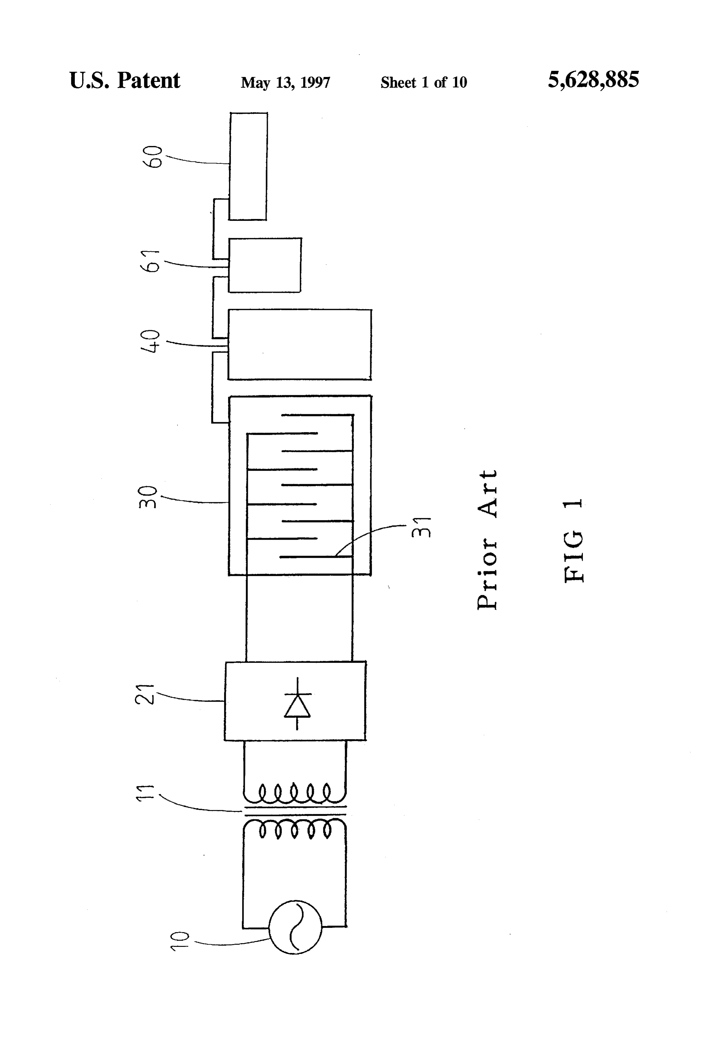
Whenever dissolvent being changed, flame with specific can switch be alleviated. Through the installation with voltage protection, whenever the fuel gas is insufficient, the temperature can be gained. However, the temperature of the 30 gas valve is automatically off and the outlets providing gas flame is invariable during usage. This makes the installation would be cut off, so the phenomenon of drawing can be lack application flexibility and needs replacement of dissol avoided. Through the fire stone installed in the welding gun, vent all the time or even replacement of the mixing tank, whenever a drawing case occurs, the flame can be instantly which is relatively inconvenient. put out by the fire stone to avoid a flame from continuous Furthermore, The industrial-used electrolytic cell is gen 35 burning. Through the voltage inside of storage tank moni erally classified into high voltage and low voltage. The one tored by a multi-control switch, if there is any out-of-order being used by oxy-hydrogen welding machine belongs to occurred in the installation as to the voltage rising up beyond low voltage electrolytic cell. The low voltage industrial-used the limit, the power would be cut off to protect the safety. extraction electrolytic cell for hydrogen and oxygen which most people know about is to use single-pole electrode plate. BRIEF DESCRIPTION OF THE DRAWINGS It is necessary for the high voltage to be lowered through FIG. 1 is the routing diagram for a prior art oxy-hydrogen transformer, then commutated and eventually input into welding machine.
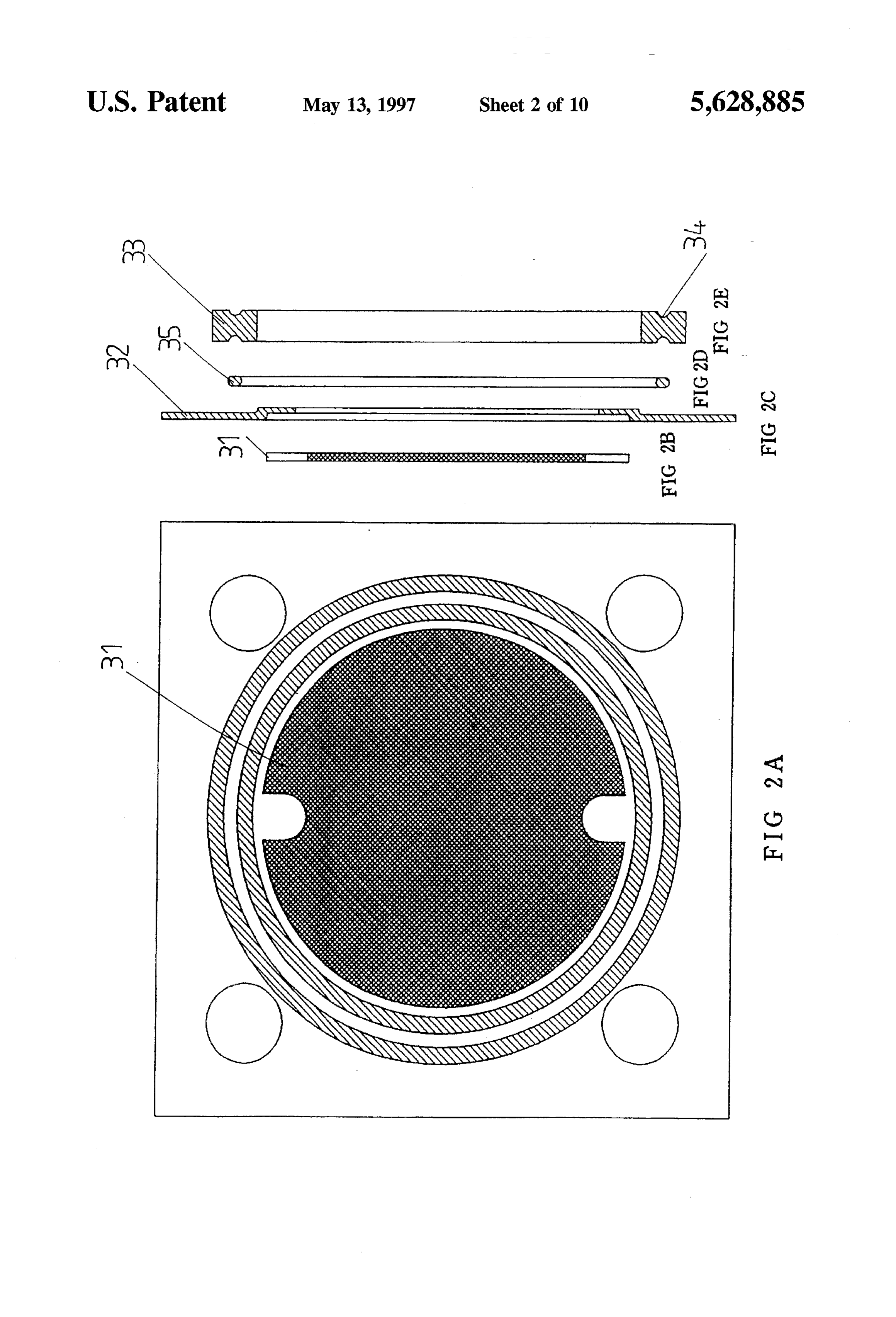
electrolytic cell as electrolysis power. Since magnetic loss is one of transformer's trait which results in low power appli FIGS. 2(a)-2(e) are the decomposition diagrams for elec cation effectiveness. Moreover, big dimension and heavy 45 trolytic cell of this invention.
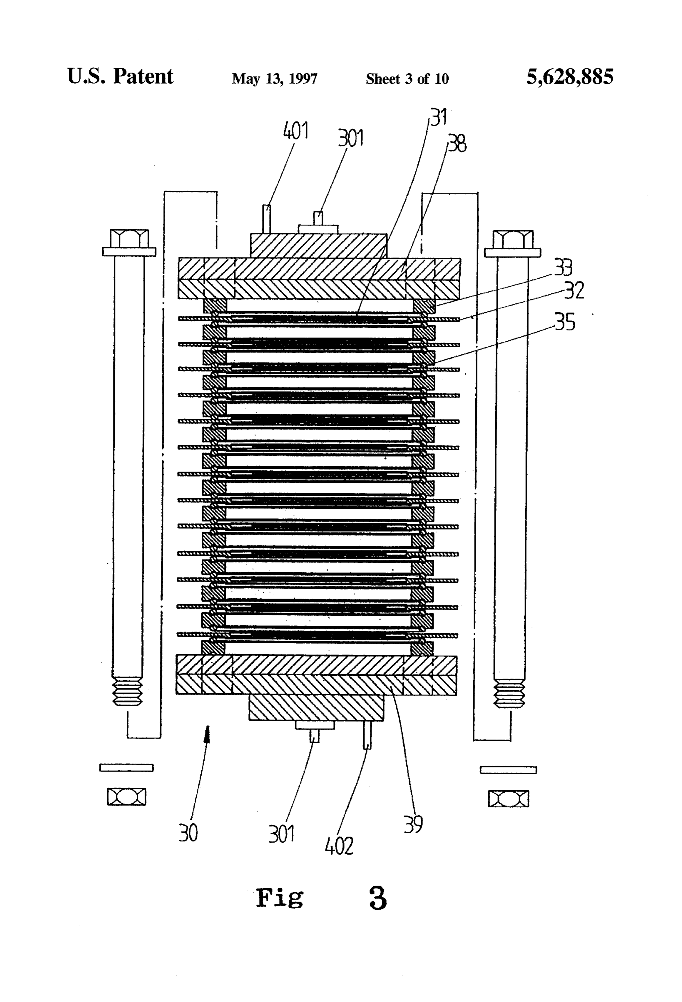
weight of transformer also makes the whole machine FIG. 3 is the dissection diagramfor the electrolytic cell of become hefty and unmovable, which is not good for the this invention.
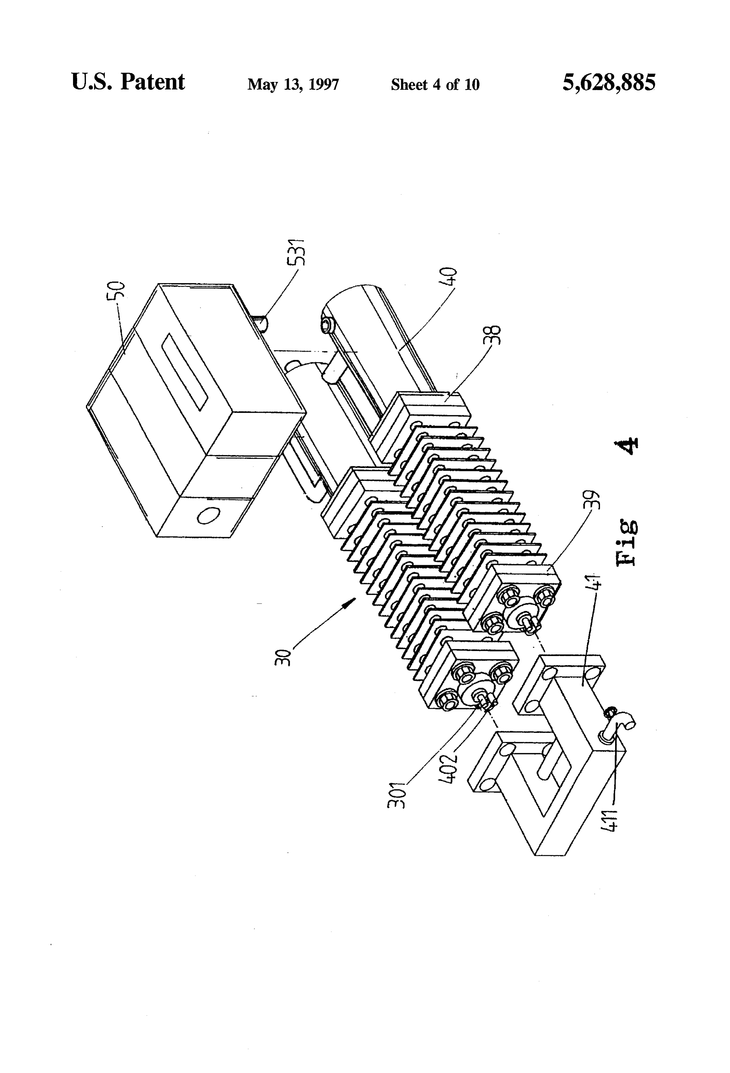
interest use. Especially most of this sort of equipments are FIG. 4 is the composition indicating diagram for this used as processing machine which lays keen emphasis on its invention.
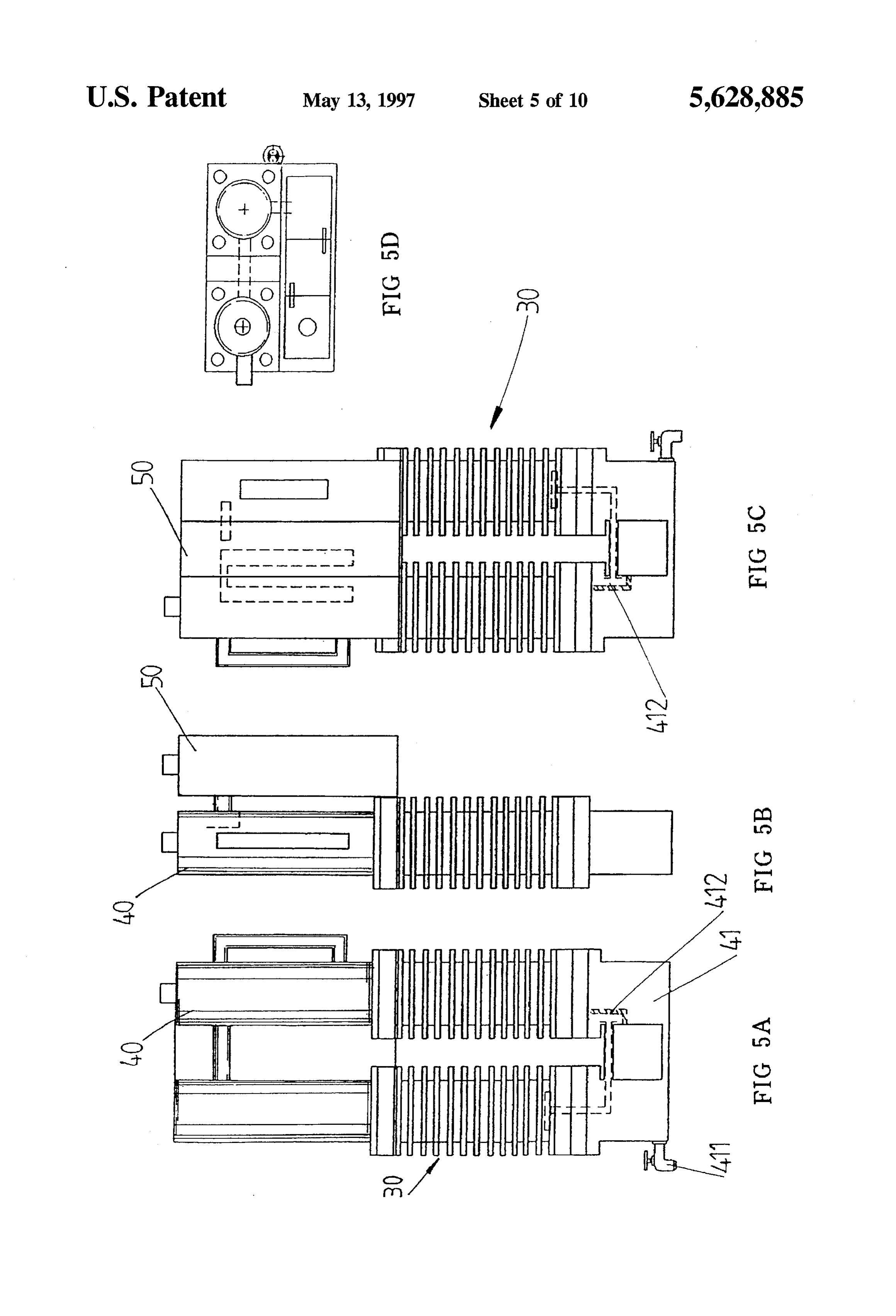
handiness and portability, so lowering down its dimension, 50 FIGS. 5(a)-5(d) are the assembly diagrams for this inven weight and enhancing its effectiveness become important tion.
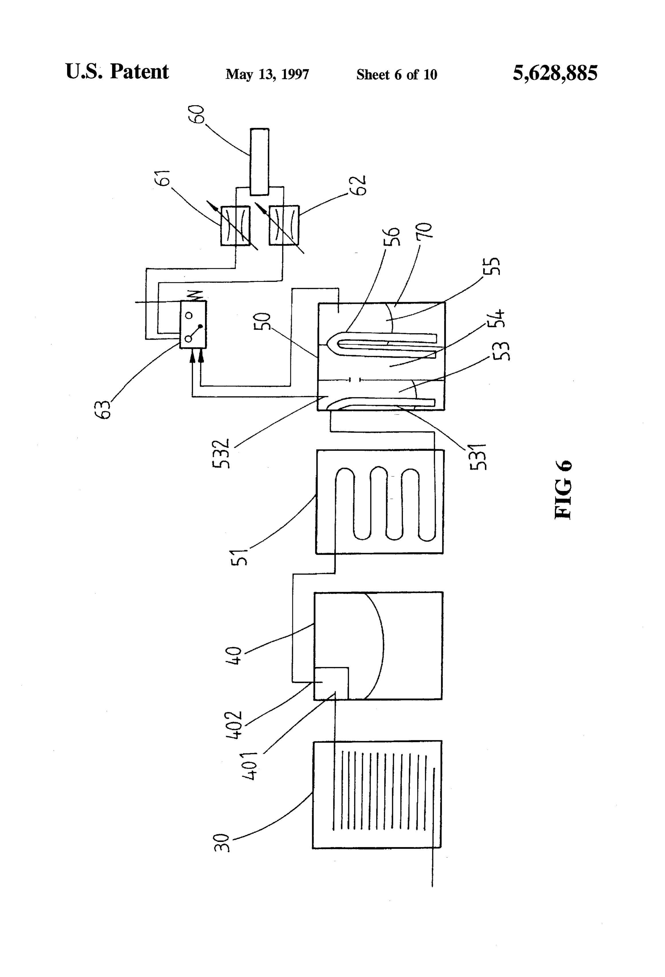
goals of research and development. Furthermore, the process FIG. 6 is the routing diagram for this invention. through transformer to lower voltage then commute into FIG. 7 is partial composition indicating diagram for this electrolytic cell, the commutator must be a material with invention.
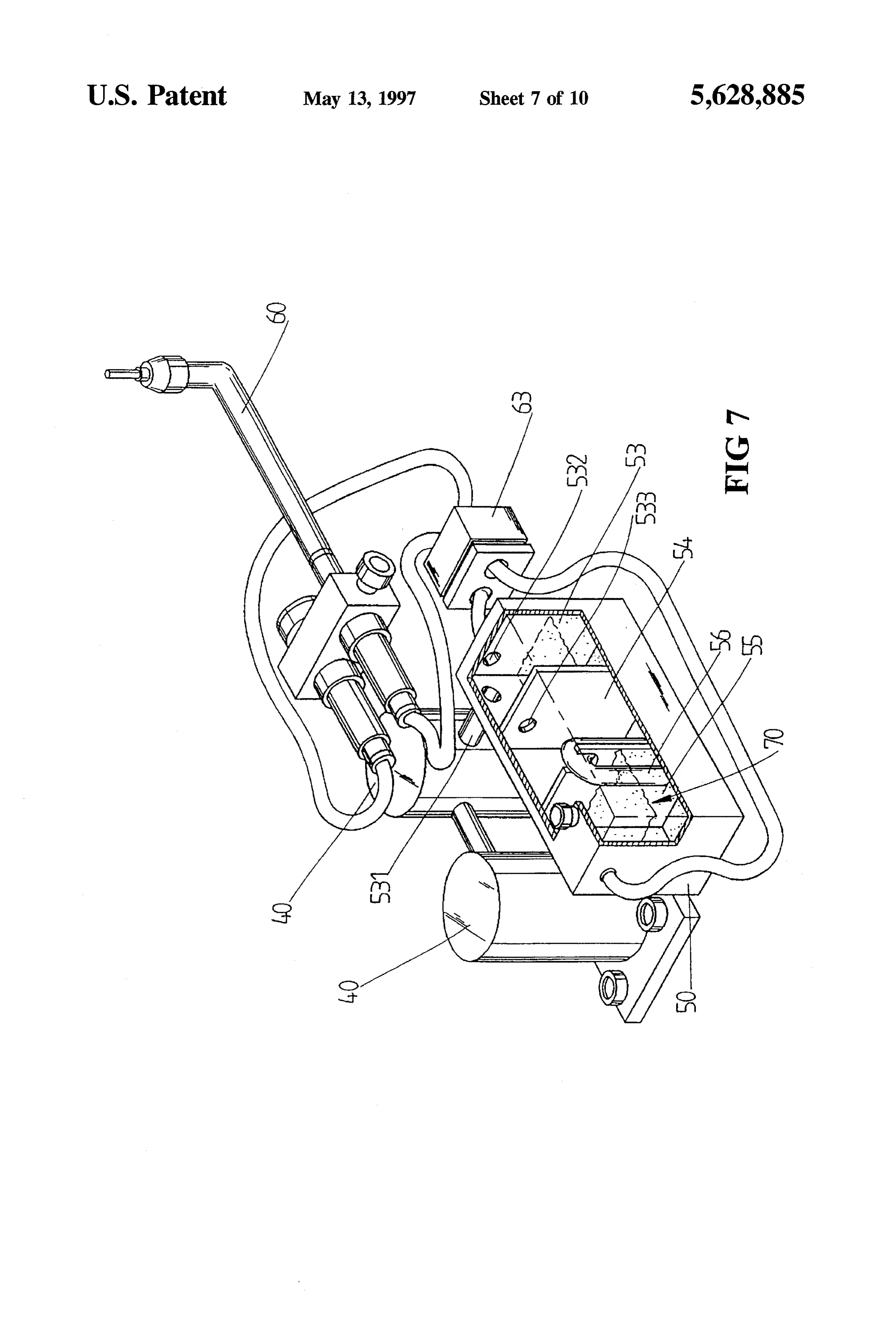
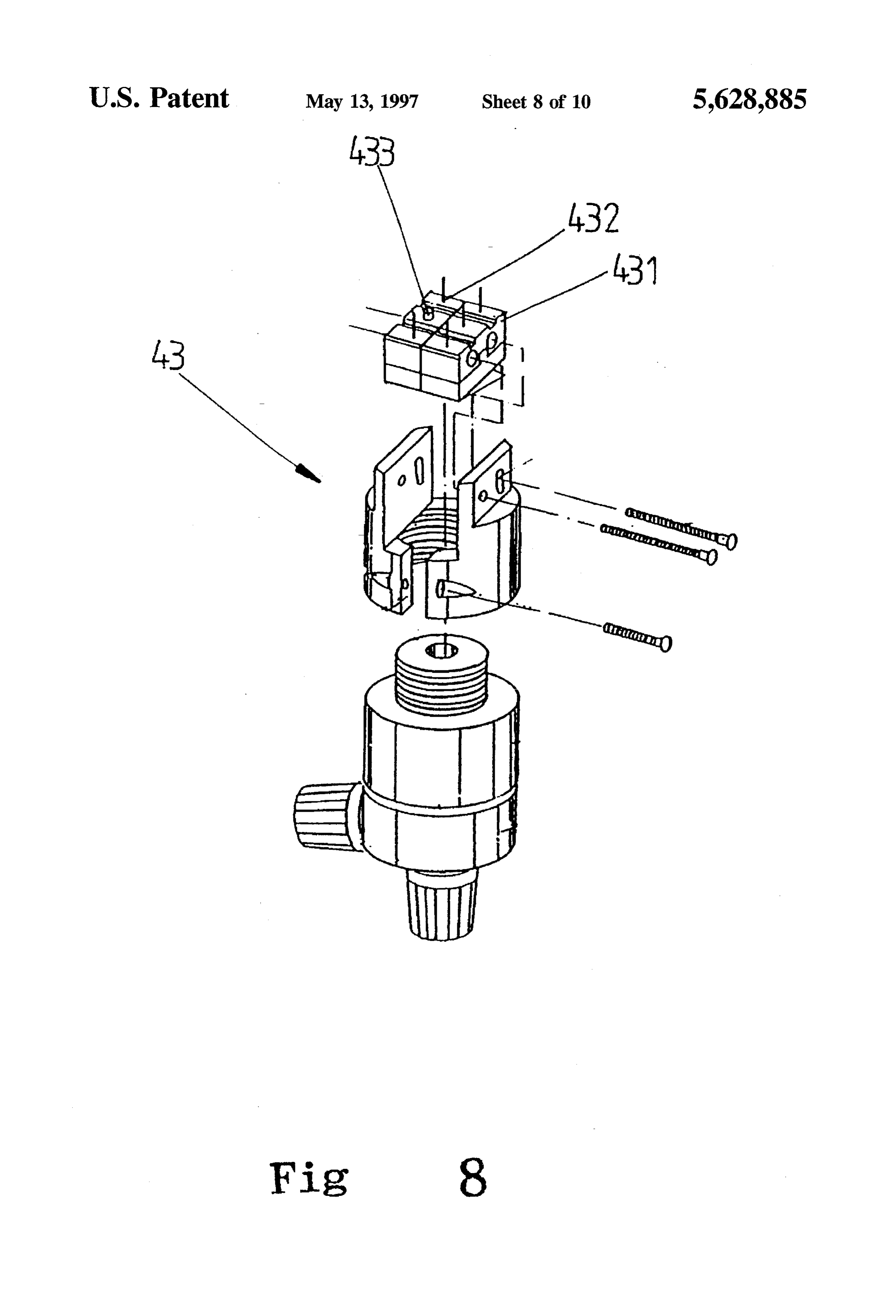
high tolerance of current which causes high heat loss, low 55 effectiveness and prone to burning out. Eventually, in order FIG. 8 is multi-control switch indicating diagram for this to generate a large volume of oxygen, it becomes necessary invention.
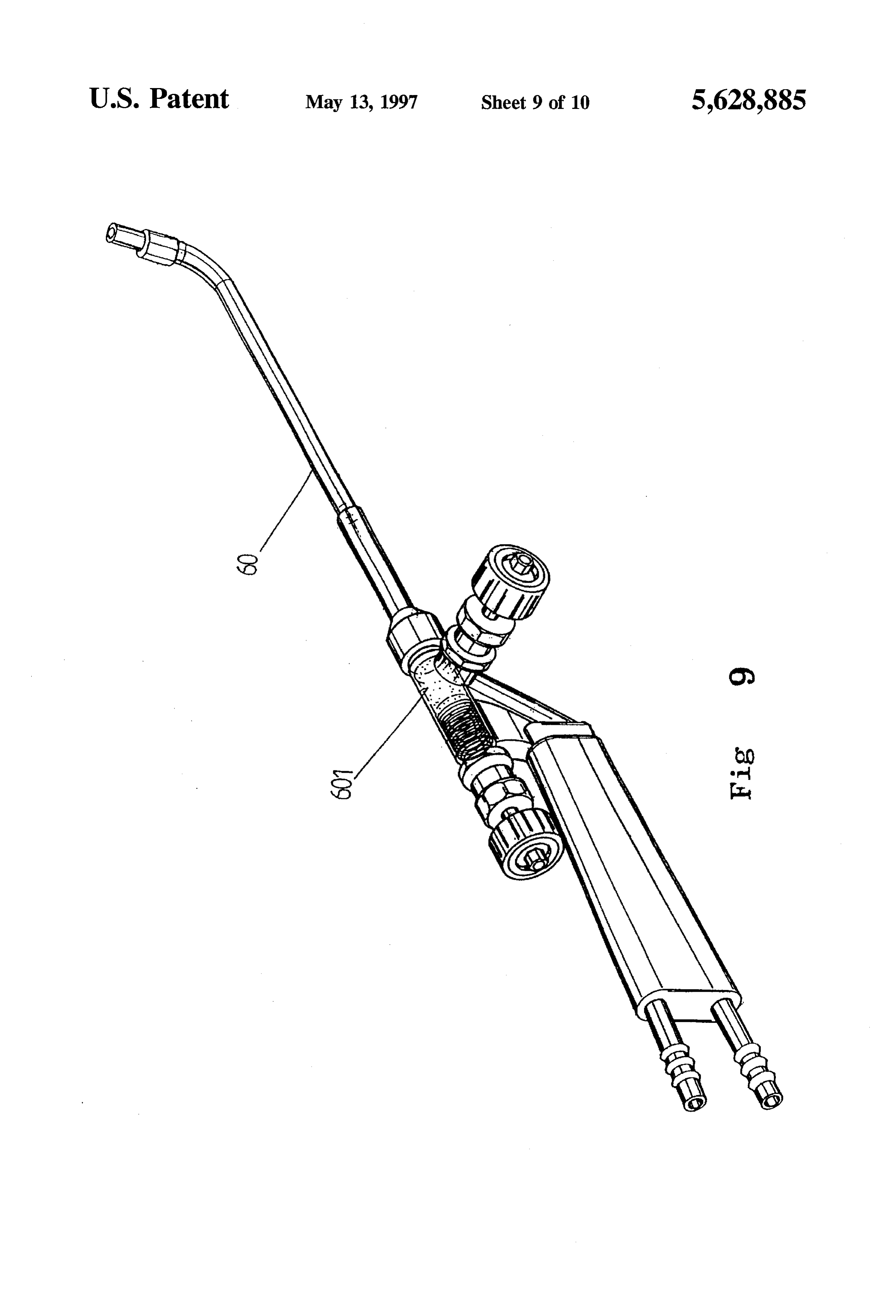
to use a huge electrolysis area of electrode plate to obtain big FIG. 9 is the composition of fire-stone installed in the current electrolysis, so the dimension and weight are needed welding gun of this invention.
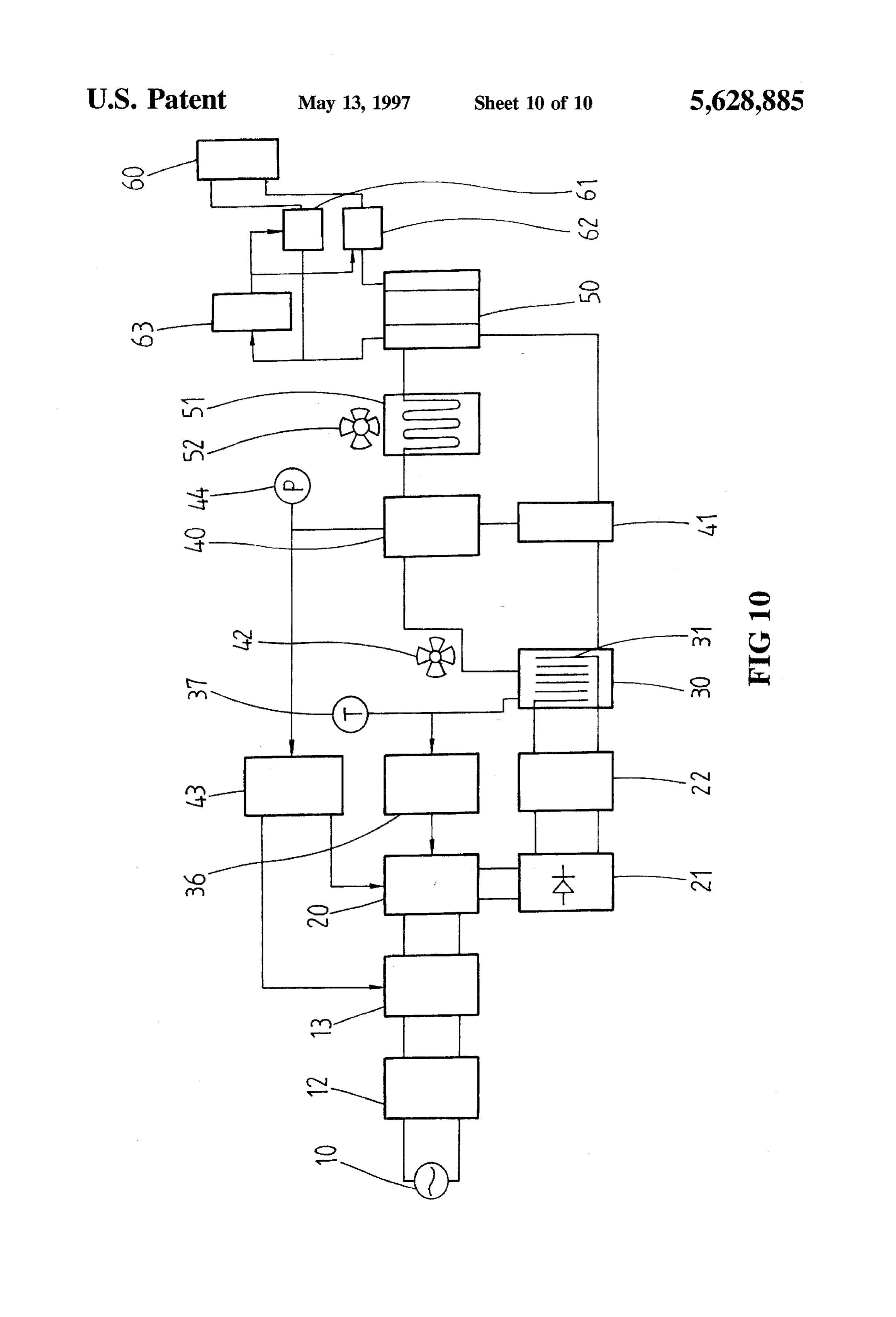
to be enlarged. All these reasons lead to the heaviness and FIG. 10 is the routing diagram of the oxy-hydrogen flame hugeness on equipment which is of low effectiveness, not welding machine for the implementation of this invention. good for the operator.
DETALED DESCRIPTION OF THE
SUMMARY OF THE INVENTION INVENTION
The primary purpose of this invention is to provide an 65 FIG. 1 is the routing diagram for a prior art oxy-hydrogen extraction installation for hydrogen and oxygen which can flame welding machine. It is to use ordinary alternating be applied to the oxy-hydrogen welding machine. It is current 10 and to be depressed through transformer 11, using
Page 13
commutator 21 to commutate it into direct current as the directly gets into storage tank 40 through electrolytic cell 30 electrolysis power for electrolytic cell 30's use. Inside of and in which the gas and liquid are segregated. In which electrolytic cell 30, there is an electrode plate 31 to resolve oxygen and hydrogen again gets into mixing tankS0 through water into hydrogen and oxygen, conveying it into storage condenser 51. In contrast with partial composition indicating 40 for storage and to control its discharge via gas valve 61 diagram on diagram 7, the mixing tank 50 is divided into 3 for welding gun 60's use. As the electrolysis electric pres chambers; they are water erasing chamber 53 for removing sure is about 1.5 to 3 voltage and the alternating current 10 moisture from the mixed gases, returning chamber 54 and is of high electric pressure at more than 110 voltage while mixing chamber 55. In order to clearly manifest the char using single-polar electrolysis, it is necessary to use trans acteristics of mixing tank 50, the gas inhaling tube 531 and former 11 to lower down the electric pressure. Yet the 10 guiding tube 56 are displayed in enlarged size (there is no transformer 11 only holds 50% of its effectiveness and turns indication of gas valve 61 & 62 in FIG. 7). Oxygen and to be very heavy due to magnetic loss and heat loss for big hydrogen is directed into water erasing chamber 53 through current; nevertheless, it is necessary to use big current to gas inhaling tube 531 to get rid of vapor contained in the generate large volume of electrolysis gas. For all these mixed gas, then oxygen and hydrogen is output as fuel reasons, the commutator 21 needs to be big and the area of 15 through exhaust outlet 532. Since it is pure mixed gas with electrode plate 31 also needs to be enlarged, which make the oxygen and hydrogen, the combustion point is high and heat whole machine heavy and unmovable. contentis low with highest flame temperature around 3640° Furthermore, the conventional way is to use single storage C.; there is a gas sharing outlet S33 installed in water erasing tank 40 for collecting gas, which makes the electrolysis chamber 53 to extract part of gases getting into returning liquid prone to overflowing into storage 40 and spilling out 20 chamber 54. There is a guiding tube 56 installed between of welding gun 60 through gas valve 61 to result in the returning chamber 54 and mixing chamber 55, one end of biggest drawback for the uncontrollable flame temperature which is dropping downward to the bottom of returning of welding gun. Taking the mixed gas of oxygen and chamber 54 and the other end of which is buried into hydrogen as fuel, which contains low heat with high flame carbohydrate dissolvent 70 inside of mixing chamber 55. temperature at 3640° C., it is possible to lower the flame 25 Oxygen and hydrogen gets into mixing chamber 55 through temperature and heighten heat content to alternate fuel guiding tube 56 and combined with carbohydrate dissolvent composition through putting carbohydrate dissolvent into 70 and alters the molecule composition or structure to get storage tank 40. Nevertheless, different carbohydrate dissol different fuel traits. There are carbohydrate dissolvents 70 vents will generate different flame temperature and heat that can be used like acetone, alcohols or volatile oils, which content. In general, the storage tank 40 with different car 30 are with different combustive temperature and heat. There bohydrate dissolvent needs to be replaced. However, the are two sorts of fuels being guided into welding gun 60; one flame temperature turns to be invariable once being is drawn out from water erasing chamber 53 directly to installed, which is pretty inconvenient. welding gun 60 through the 1st gas valve 61, which is a This invention provides a way, by using a storage tank mixed gas with oxygen and hydrogen in a high combustive matching mixing tank, to improve the drawback of the prior 35 temperature and low heat. The other is drawn out from art. Referring now to FIGS. 2(a)-(e) and 3, the storage tank mixing chamber 55 to welding gun 60 through 2nd gas valve 40 is shown connected on top of electrolytic cell 30. The 62, which is a gas combined with carbohydrate dissolvent in electrolytic cell 30 is composed of several pieces of elec a low flame temperature and high heat. To control the trode plates 31 which are lined in a parallel row. Each discharge ratio through gas valve 61 & 62, the flame electrode plate 31 is stuck to a heat dispersing board 32, the temperature can be adjusted within the range of 800° to gap between two dispersing board 32 is divided by a insulate 3640° C.
pad 33. In which there is a concave trough 34 installed in the In order to provide protective function, there is a pressure front and back side of the insulate pad 33. There is an switch 63 installed to monitor the gas pressure inside of insulate oil seal 35 inset into concave trough 34 to avoid water erasing chamber 53 and control gas valve 61 & 62. contacting as to cause short circuit. Lining up aforemen 45 When there is insufficient pressure in the water erasing tioned assemblies and connecting the farthest layer with chamber 53, pressure switch 63 will immediately close gas upper cover 38 and lower cover 39, connecting electrode valve 61 & 62 to avoid drawing phenomenon. The mixing joint 301 individually with electrode plate 31 in the most tank 50 itself also has protective function, eg: if there is a Outer layer, a multi-polar composition with connection in drawing occurred, the oxygen and fuel is scarce inside of Series and a electrolytic cell 30 without cover are formed. 50 mixing chamber 55 which would be burned out in a With reference now to FIGS. 4 and5(a)-(d) also, the storage minute-this is so called liquid extinguishment. The inner tank 40 is shown closely fixed on top of electrolytic cell 30 pressure generated within a minute would thrust dissolvent and circulated with upper cover 38 through gas intake 401 70 into guiding tube 56 to hinder the fuel gas from continu so that the electrolysis liquid can be complemented directly ously entering in the meantime to alleviate the pressure as to through storage tank 40 with no need of opening electrolytic 55 avoid mechanical damage and reach the goal of extinguish cell 30. After getting through electrolytic cell 30, the elec ment and safety protection.
trolytic liquid should be directed into filtering tank 41 for Please refer to FIG. 8, which is the indication figure for filter through exhaust outlet 402. The filtering tank 41 is the multi-control switch of this invention. The pressure connected with lower cover 39 and somewhere appropriate inside of storage tank 40 is rather high, which could cause on top of which there is a row of rejecting outlets 411 and 60 danger easily. In order to provide safety measures, there is a filtering net 412 installed. The residue filtered out from the a multi-control switch 43 installed to monitor the pressure electrolysis liquid will be rejected through rejecting outlet inside of storage tank 40. It is composed of a micro-active 411. The liquid after electrolysis will be guided back to Switch 431 and a limitation switch 432, which are individu electrolytic cell 30 for recycling use. The oxygen and ally connected with pressure power and pressure meter via hydrogen will be directed into mixing tank 50 through gas 65 a 3-plug tube to know the amount of air pressure. When air inhaling tube 531 for use (as shown on FIG. 4 & 5). The pressure is within the range of a preset limit, only the routing figure is as shown in FIG. 6, electrolytic liquid micro-active switch 431 is needed for switch alternating
Page 14
S 6 action; yet when air pressure exceeds the preset limit, the a returning chamber in fluid communication with said limitation switch 432 would start acting and cut off the water erasing chamber for receiving a portion of said powerfor whole installation. The reset button 433 on top of first gas in said water erasing chamber; limitation switch 432 can be pressed to place the whole a mixing chamber in fluid communication with said operation back to normal until all the warning is released. returning chamber for receiving said portion of said As shown in FIG. 9, there is a fire-stone installed inside first gas in said returning chamber, said mixing cham of welding gun 60 of this invention to further provide ber having a gas altering medium disposed thereinfor protection. The fire-stone 601 is installed inside of the output contacting and transforming said portion of said first passage after the mixture of two fuels. If a drawing case gas into a second gas;
occurs, the flame would be put out by the fire-stone. 10 a first exhaust outlet located on said water erasing cham
FIG. 10 is the routing figure of oxy-hydrogen flame ber for an amount of said first gas to exit therethrough; welding gun for the implementation of this invention. Of which electric power 10 being used is of ordinary voltage, a second exhaust outlet located on said mixing chamber can be 110, 220, 380 or 440 voltage and so forth which for an amount of said second gas to exit therethrough; passes through a no-fuse switch 12 and a magnetic switch 5 wherein, a fuel is formed from said amount of said first 13. Magnetic 13 is for the purpose of protection, when an gas and said amount of said second gas. out-of-order occurs, it would be controlled for cutting of 2. An electrolytic apparatus as defined in claim 1, further power and stopping continuous action. Magnetic Switch 13 comprising:
is connected to control circuit 20. The voltage can be varying means for varying said amount of said first gas adjusted and input into commutator 21 to commutate it into and said amount of said second gas such that said fuel direct current. Control circuit 20 provides the electric power 20 is formed with desired combustion characteristics. for other equipment assemblies and controls the go-or-stop 3. An electrolytic apparatus as defined in claim 2, further of electrolysis action. The electric pressure after commutat comprising:
ing through commutator 21 is still high voltage would be the direct current for electrolysis use. The direct currentis input a welding gun for receiving said first amount of said first into electrolytic cell 30 through a polarity alternating switch 25 gas and said second amount of said second gas from 22 which could alternate the input power polarity, so the said varying means during welding. positive and negative pole inside of electrolytic cell 30 can 4. An electrolytic apparatus as defined in claim 2, be alternated and the specific electrode plate would not be Wherein:
encircled with electrolysis mud to help extend the expiration said varying means comprises a first gas valve in fluid of the electrolytic cell. The oxygen and hydrogen and 30 communication with said first exhaust outlet and a overflowed electrolytic liquid or vapor would be sent to second gas valve in fluid communication with said storage tank 40 in which the returning liquid returning back second exhaust outlet, to electrolytic tank30 through filtering tank 41 for recycling wherein, said amount of said first gas is determined by use. It is possible to installafan 42 between filtering tank41 said first gas valve and said second amount of said and electrolytic cell 30 to keep electrolytic cell 30 to work 35 second gas is determined by said second gas valve. under appropriate temperature and to use temperature 5. An electrolytic apparatus as defined in claim 4, further control switch to get more protection. When the temperature comprising:
of electrolytic cell 30 exceeds set value, the gas valve 61 & a welding gun in fluid communication with said first gas 62 would be closed to stop providing gas. The fuel gas will continue to be provided until the electrolytic liquid flowing valve and said second gas valve for receiving said fuel and circulating and lowering to the appropriate value. If the during welding.
temperature of electrolytic cell30keeps going up to the limit Wherein:6. An electrolytic apparatus as defined in claim 5, value, the power of commutator 21 sent by control circuit 20 should be cut off to hinder the electrolysis from continuing said gas altering medium comprises carbohydrate dissol process. Temperature meter 37 is for the use of observing 45 Wents.
temperature of electrolytic cell 30; the oxygen and hydrogen 7. An electrolytic apparatus as defined in claim 6, after segregation inside of storage tank 40 needs to be further wherein:
dried through condenser 51 so as to be taken as fuel being said water erasing chamber, said returning chamber and input into mixing tank 50 for use. In order not to cause said mixing chamber comprise a mixing tank. danger by the too high voltage inside of storage cell 40, there 50 8. An electrolytic apparatus as defined in claim 7, further is a pressure meter 44 for observation and a multi-control comprising:
switch 43 for monitoring of the pressure inside of storage a gas sharing outlet positioned between said water erasing tank 40. Through control circuit 20 to control electrolytic chamber and said returning chamber for providing fluid power, the pressure can be kept within a tolerable range. If communication therebetween; and there is out-of-order occurred in the installation which keeps 55 a guiding tube positioned between said returning chamber the pressure going up as to exceed the limit, the magnetic and said mixing chamber for providing fluid commu switch 13 would directly cut off the power to reach the nication therebetween.
function of safety protection. 9. An electrolytic apparatus as defined in claim 8, further What is claimed is: comprising:
1. An electrolytic apparatus, comprising: a gas inhaling tube positioned between said storage tank an electrolytic cell for producing a first gas from an and said water erasing chamber for providing fluid electrolytic solution; communication therebetween.
a storage tank in fluid communication with said electro 10. An electrolytic apparatus as defined in claim 9, lytic cell for storing said first gas; wherein:
a water erasing chamberinfluid communication with said 65 said gas sharing outletis positioned at a top portion of Said storage tankfor removing moisture from said first gas water erasing chamber and at a top portion of said received from said storage tank; returning chamber,
Page 15
said guiding tube has a first end and a second end, said contained within said inner periphery of said insulate first end of said guiding tube entering a top portion of ring during electrolysis.
said returning chamber and extending to a bottom 16. An electrolytic apparatus as defined in claim 15, portion of said returning chamber, said second end of wherein:
said guiding tube entering a top portion of said mixing 5 said electrolytic cell further includes a polarity alternating chamber and extending to a bottom portion of said switch electrically connected to said electrode plates. mixing chamber, and 17. An electrolytic apparatus as defined in claim 16, said gas inhaling tube entering said water erasing chamber further comprising:
at a top portion and extending to a bottom portion varying means for varying said amount of said first gas
and said amount of said second gas such that said fuel 11. An electrolytic apparatus as defined in claim 10, is formed with desired combustion characteristics. wherein: 18. An electrolytic apparatus as defined in claim 17, said electrolytic cell includes a plurality of electrode further comprising:
plates, a plurality of heat dispersing boards Supporting 15 a welding gun for receiving said first amount of said first said electrode plates, at least one insulate pad having a gas and said second amount of said second gas from trough defined on opposite faces, and an insulate oil said varying means during welding. seal disposed in each trough of said insulate pad, said 19. An electrolytic apparatus, comprising: heat dispersing boards being in alternating alignment an electrolytic cell for producing a first gas from an with said insulate pad. electrolytic solution;
12. An electrolytic apparatus as defined in claim 11, 20 wherein: a storage chamber in fluid communication with said said insulate pad further includes an inner periphery, said electrolytic cell for receiving said first gas; electrode plates and said electrolytic solution being a mixing tank including a water erasing chamber and a contained within said inner periphery of said insulate 25 mixing chamber, said water erasing chamber being in ring during electrolysis. fluid communication with said storage chamber for 13. An electrolytic apparatus as defined in claim 12, receiving said first gas from said storage chamber and wherein, said mixing chamber being in fluid communication said electrolytic cell includes a plurality of electrode with said water erasing chamber for receiving a portion plates, a plurality of heat dispersing boards supporting 30 of said first gas in said water erasing chamber, said said electrode plates, at least one insulate pad having a mixing chamber having a gas altering medium disposed trough defined on opposite faces, and an insulate oil therein for contacting and transforming said portion of seal disposed in each trough of said insulate pad, said said first gas into a second gas; heat dispersing boards being in alternating alignment a first exhaust outlet located on said mixing tank for an with said insulate pad. 35 amount of said first gas to exit therethrough;
14. An electrolytic apparatus as defined in claim 1, a second exhaust outlet located on said mixing tankfor an wherein: amount of said second gas to exit therethrough; said electrolytic cell includes a plurality of electrode wherein, a fuel is formed from said first gas and said plates, a plurality of heat dispersing boards supporting second gas.
said electrode plates, at least one insulate pad having a 40 20. An electrolytic apparatus as defined in claim. 19, trough defined on opposite faces, and an insulate oil further comprising:
seal disposed in each trough of said insulate pad, said a valve assembly in fluid communication with said fuel heat dispersing boards being in alternating alignment and said valve assembly being adjustable such that said with said insulate pad and said insulate pad including fuel characteristics is variable. an inner periphery, said electrode plates and said elec 45 21. An electrolytic apparatus as defined in claim. 19, trolytic solution being contained within said inner further comprising:
periphery of said insulate ring during electrolysis. a welding gun in fluid communication with said first 15. An electrolytic apparatus as defined in claim 14, exhaust outlet and said second exhaust outlet for wherein: receiving said fuel during welding. said insulate pad further includes an inner periphery, said 50 electrode plates and said electrolytic solution being k :: :: * :
Provenance
- Collection
- Cited prior art
- Original PDF
- patentimages.storage.googleapis.com →
- Filed
- 1995-11-13
- Pages
- 15
- Method
- pdftotext (the PDF's own text layer) + pdftoppm 300dpi page scans
- Source
- Google Patents bibliographic record
- Granted
- 1997-05-13
- Inventors
- Yang C. Lin
- Transcribed from
- patentimages.storage.googleapis.com →