patent · US5678626
Air conditioning system with thermal energy storage and load leveling capacity
21 October 1997
Page 1 — bibliographic record
United States Patent (19) 11 Patent Number: 5,678,626 Giles 45 Date of Patent: Oct. 21, 1997 54 AIR CONDITIONING SYSTEM WITH 4,909,041 3/1990 Jones ........................................... 62/99 THERMAL ENERGY STORAGE AND LOAD 4,916,916 4/1990 Fischer .................................. 6243OX LEVELNG CAPACTY 4,940,079 7/1990 Best et al. ... ... 165/18 X 521,029 5/1993 Uselton et al. . ... 62/324.5 75 Inventor: Theodore C. Gilles, Dallas, Tex. 5,255,526 10/1993 Fischer ........................................ 62/59 5,307,642 5/1994 Dean ....... 62/332X 73 Assignee: Lennox Industries Inc., Dallas, Tex. 5,467,812 11/1995 Dean et al. ............................... 165/62 Primary Examiner William E. Wayner 21 Appl. No.: 560,376 Attorney, Agent, or Firm-W. Kirk McCord 22 Filed: Nov. 17, 1995 57 ABSTRACT Related U.S. Application Data A vapor compression air conditioning (cooling and heating) system adapted for operation to reduce the consumption of
I63) Continuation-in-part of Ser. No. 293,875, Aug. 19, 1994, electric power during peak periods of demand for power is Pat No. 5,467,812. characterized by four refrigerant circuits. A first circuit (51 int. Cl. ............ F25B 25/00; F25B 1300 includes a compressor, a first heat exchanger and a second heat exchanger. A second circuit comprises the compressor, 52 U.S. Cl. ........................... 165/62; 62/59; 62/DIG. 2 the first heat exchanger and a third heat exchanger. A third 58 Field of Search .......................... 62/59,332, DIG. 2, circuit comprises the third heat exchanger, a refrigerant 62/.430, 324.1; 165/62 pump and a thermal energy storage unit characterized by a
tank having a thermal energy storage medium disposed therein. A fourth circuit includes the thermal energy storage
first heat exchanger is an outdoor heat exchanger. The 3,563,304 2/1971 McGrath ............................... 165/62 X second and fourth heat exchangers are indoor heat exchang 4,044,568 8/1977 Hagen ......................................... 62/73 ers in heat transfer relationship with the fluid (e.g., indoor 4,135,571 1/1979 Tamblyn etal 62/434 X supply air) to be cooled or heated. A first refrigerant, 4,192,146 3/1980 Crede ............................................ 62.2 preferably a compressible phase change fluid, is circulated in 4,253,309 3/1981 Abrahamsson et al. ................ 62/98 X 4,256,475 3/1981 Schafer ................................ 237/28 X the first and second circuits by the compressor. A second 4,375,831 3/1983 Downing, Jr. ........................ 62/260 X refrigerant, preferably an incompressible liquid, is circulated 4,380,156 4/1983 Ecker ........... 62238.7 X in the third and fourth circuits. The system is operable in 4,527,618 7/1985 Fyfe et al. ............ 62/238.6 X plural cooling and heating modes to provide load leveling 4,608,836 9/1986 MacCracken et al. ......... 62/235 between vapor compression heating and cooling using the 4,645,908 2/1987 Jones ........................ ... 62/160 X compressor and heating and cooling using the thermal 4,671,077 6/1987 Faradis ................................... 62/324.1 energy storage unit, to achieve reduced power consumption 4,718,248 1/1988 Fisher ..................................... 62/238.7 during peak electrical power demand periods. 4,735,064 4/1988 Fischer ...................................... 62/430 4,753,080 6/1988 Jones et al. ................................. 62/59 4,809,516 3/1989 Jones ......................................... 62/160 32 Claims, 4 Drawing Sheets
& 48
Page 2
Drawing sheet — no readable text.
Page 3
Drawing sheet — no readable text.
Page 4
Drawing sheet — no readable text.
Page 5
Drawing sheet — no readable text.
Page 6
AR CONDITIONING SYSTEM WITH The thermal energy storage unit may be provided with a THERMAL ENERGY STORAGE AND LOAD heating element to heat the phase change material in the tank LEVELNG CAPACTY and may be operated to act as both a heat source and a heat sink. The arrangement of the components of the system is
CROSS-REFERENCE TO RELATED such that the system may be operated to provide both heating APPLICATION and cooling of indoor air, for example, at predetermined This application is a continuation-in-part of application "load” conditions while requiring approximately only one Ser. No. 08/293,875, filed Aug. 19, 1994, now U.S. Pat. No. half of the power required by conventional heating and 5,467,812. cooling systems for meeting the same thermal load require 10 ments.
TECHNICAL FIELD The system is capable of being operated in at least eight The present invention pertains to air conditioning systems different modes (four cooling modes and four heating with thermal energy storage and in particular to an improved modes), not including two transitory modes for moving the air conditioning system with thermal energy storage and 15 refrigerant charge to and from the thermal energy storage load leveling capacity. unit. During so-called off-peak electricity usage periods, the system is operable in a first cooling mode to circulate
BACKGROUND ART refrigerant through the thermal energy storage tank to cool Electric power suppliers or so-called electric utilities the phase change material which, if such comprises water, is cooled sufficiently to manufacture a substantial amount of charge higher rates for both summer and winter peak cooling 20 ice and heating conditions. For example, in warm weather mayinbetheinterposed storage tank. A refrigerant liquid storage vessel in a refrigerant circuit between the conditions, peak electricity usage is usually in the afternoon outdoor heat exchanger operating as a condenser and the hours and in the heating seasons peak electricity usage may storage tank to store excess refrigerant during the first be in the early morning hours when heating systems return to normal daytime temperature settings and electric water 25 cooling mode.
heaters, for example, are subject to above-normal usage. A second cooling mode of operation of the system is So-called thermal energy storage systems have been devel characterized by circulating refrigerant from the compressor oped for minimizing the use of electrical energy during peak to the outdoor heat exchanger operating as a condenser and periods. U.S. Pat. Nos. 5,211,029 (to Uselton, et al), issued then to one of the indoor air heat exchangers operating as an evaporator to provide direct indoor air cooling in a conven
May 18, 1993 and 5,307,642 (to Dean), issued May 3, 1994, 30 tional assigned to the assignee of the present invention, and U.S. manner.
Pat. 5.255,526 (to Fischer) issued Oct. 26, 1993 describe air A third cooling mode of operation of the system provides conditioning systems which utilize a thermal energy storage for circulation of refrigerant between the storage tank and tankhaving a phase change material, such as water, disposed one of the indoor air heat exchangers operating as an therein. During off-peak electricity usage periods, refriger 35 evaporator by a liquid pump having substantially reduced antis circulated through aheat exchanger in the storage tank power requirements while providing approximately half of to produce ice, and during peak electricity usage periods, the total cooling capacity of the system. refrigerant is circulated between the storage tank and an In accordance with yet a further aspect of the invention, indoor heat exchanger coil or evaporator by a low-power the system may be operated in a fourth cooling mode consuming pump to provide the requisite cooling effect. wherein full capacity cooling is provided by circulating Thermal energy storage systems may also be used for refrigerant from the compressor through the outdoor heat heating, as shown in U.S. Pat. 4,645.908 (to Jones). exchanger operating as a condenser and one of the indoor air So-called load leveling systems provide for simultaneous heat exchangers operating as an evaporator while, operation of a thermal energy storage unit and a vapor simultaneously, refrigerant is circulated through a circuit compression refrigerant circuit, as shown in U.S. Pat. No. 45 which includes the storage tank and the other one of the 4.916,916 (to Fischer). indoor air heat exchangers operating as an evaporator by However, known types of load leveling systems do not way of the refrigerant circulating pump. In this mode of provide for two independent indoor heat exchangers which operation, full cooling capacity of the system is provided at provide cooling simultaneously from both a thermal energy approximately one-half of the electrical power which would storage unit and from a vapor compression refrigerant 50 be required of a conventional vapor compression refrigera circuit. Still further, known types of load leveling systems do tion or air conditioning system. not provide for both heating and cooling by simultaneously Still further, the invention provides for four heating operating a thermal energy storage unit and a vapor com modes of operation, including a first heating mode wherein pression refrigerant circuit with respective separate indoor an electrical resistance heating element, for example, dis heat exchangers. It is to these ends that the presentinvention 55 posed in the thermal energy storage tank, is operated during has been developed. off-peak electrical usage periods to heat the phase change
SUMMARY OF THE INVENTION
material in the storage tank. In a second heating mode of operation, direct heat generation is provided by the
The present invention provides a unique load-leveling compressor, the condenser and one of the indoor heat type air conditioning system. The system includes a exchangers operating in a reverse or so-called heat pump compressor, an outdoor heat exchanger, dual indoor heat mode wherein one of the indoor heat exchangers is used as exchangers, and a thermal energy storage unit. The thermal a condenser and the outdoor heat exchanger functions as an energy unit includes a storage tank with a phase change evaporator.
material, such as water, disposed in the tank and arefrigerant The invention provides a third heating mode wherein circulating pump for circulating refrigerant between the 65 refrigerantfluidis heated by the phase change material in the thermal energy storage unit and one of the indoor heat thermal energy storage tank and the refrigerant fluid is exchangers. circulated by the pump to one of the indoor heat exchangers
Page 7
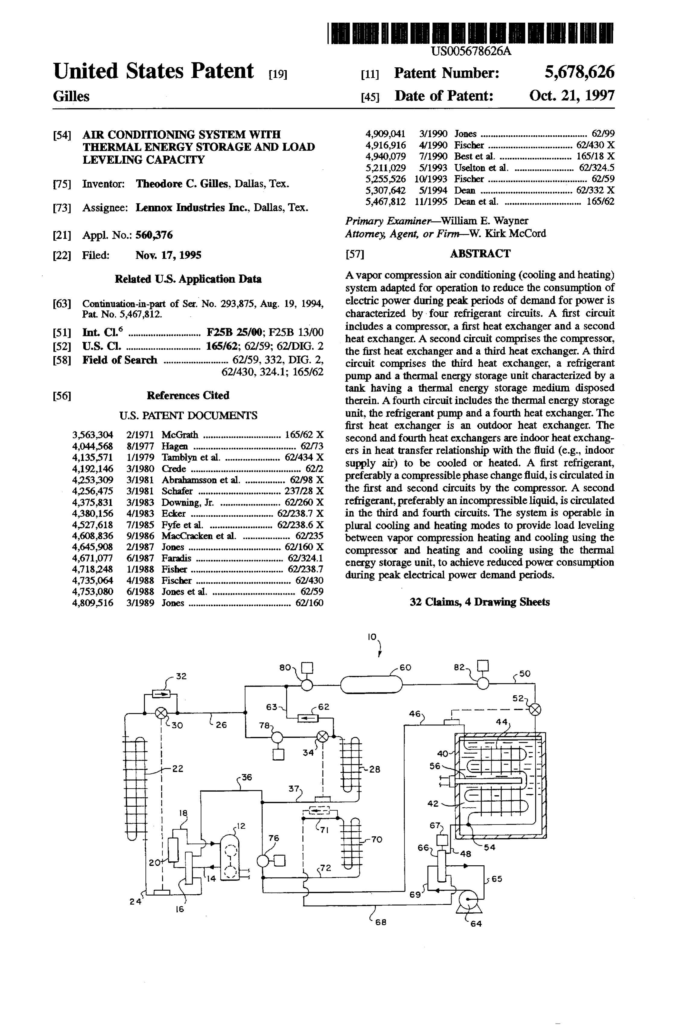
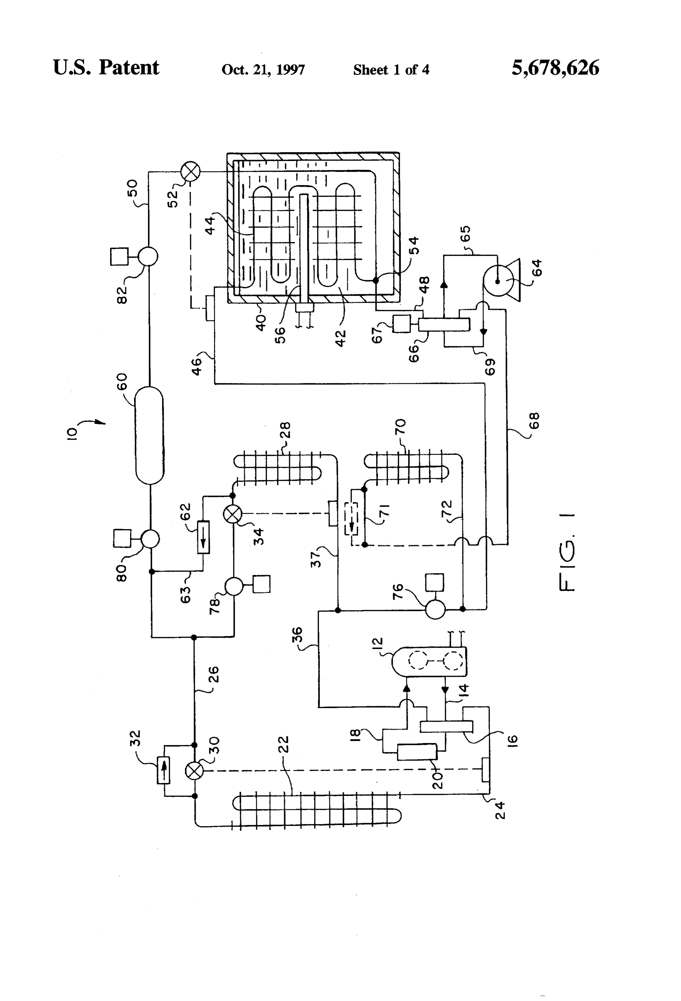
to provide heating of the indoor air. Still further, the inven valve 16 by a conduit 24 and by way of a conduit 26 to a tion provides a fourth heating mode in which the system is second refrigerant-to-air heat exchanger 28, which is located capable of full capacity heating wherein refrigerant is cir indoors in heat exchange relationship with an indoor space culated between the compressor and one of the indoor heat to be conditioned. A conventional superheat controlled or exchangers in the heat pump mode while simultaneously thermostatic-type thermal expansion device 30 and a check refrigerant is circulated between the thermal energy storage valve 32 are operably interposed in the conduit 26 to allow tank and the other indoor heat exchanger to provide full the heat exchanger 22 to operate as an evaporator in a heat capacity heating. pump operating mode. A second thermostatic-type thermal The system provides several advantages which will be expansion device 34 is interposed in the conduit 26 upstream of the heat exchanger 28, which operates as an evaporator recognized by those of skill in the art. In particular, a system 10 when is provided wherein both cooling and heating requirements air, forthe system is operating to provide cooling to indoor example, flowing over the heat exchanger 28. Refrig are met with approximately one-half of the electrical power erant fluid is returned to the compressor from the heat requirements of conventional vapor compression air condi tioning systems or heat pumps. The system provides load exchanger 28 by way of conduits 36, 37 and the reversing leveling in both cooling and heating operations to take 15 valve 16. The aforementioned portion of the system 10 advantage of off-peak electrical power pricing. High capac forms a first refrigerant circuit.
ity cooling requirements are met by the thermal energy The system 10 also includes a thermal energy storage unit storage unit and by the plural indoor cooling load heat comprising an insulated tank 40, which is operable to exchangers. In a similar manner, high capacity heating contain a quantity of suitable phase change material such as requirements are met by the thermal energy storage tank 20 water 42. The thermal energy storage unit may be adapted supplying heat by way of one of the indoor air heat exchang for refrigeration applications. For example, glycol or salt ers and the other indoor heat exchanger also functions as a may be added to water 42 to lower the freezing temperature substantially below 32° F., for example, to approximately condenser while the system is operating as a heat pump.
Peak cooling and heating loads can be easily met with the 20° F. When operated with a standard refrigeration system system of the invention while requiring substantially 25 (not shown) instead of an air conditioning system, evapo reduced electrical power demand. The system may be used rating temperatures on the order of 33° F (instead of 45 F. in place of conventional commercial and residential heat for an air conditioning system) may be achieved, which is pumps which use electrical resistance-type heating suitable for refrigeration applications. A third heat elements, for example, to meet peakheat load requirements. exchanger 44 is immersed in the water 42 within the tank 40 Those skilled in the art will further appreciate the above 30 and is connected to a refrigerant fluid transfer conduit 46, a mentioned features and advantages of the invention together second refrigerant fluid transfer conduit 48 and a third with other superior aspects thereof upon reading the detailed conduit 50 having a conventional thermal expansion device description which follows in conjunction with the drawing. 52 interposed therein. The conduit SO, heat exchanger 44 and conduit 48 are interconnected at a suitable junction 54
BRIEF DESCRIPTION OF THE DRAWING 35 within the tank 40. The above-described thermal energy storage unit also includes a heating element 56 suitably
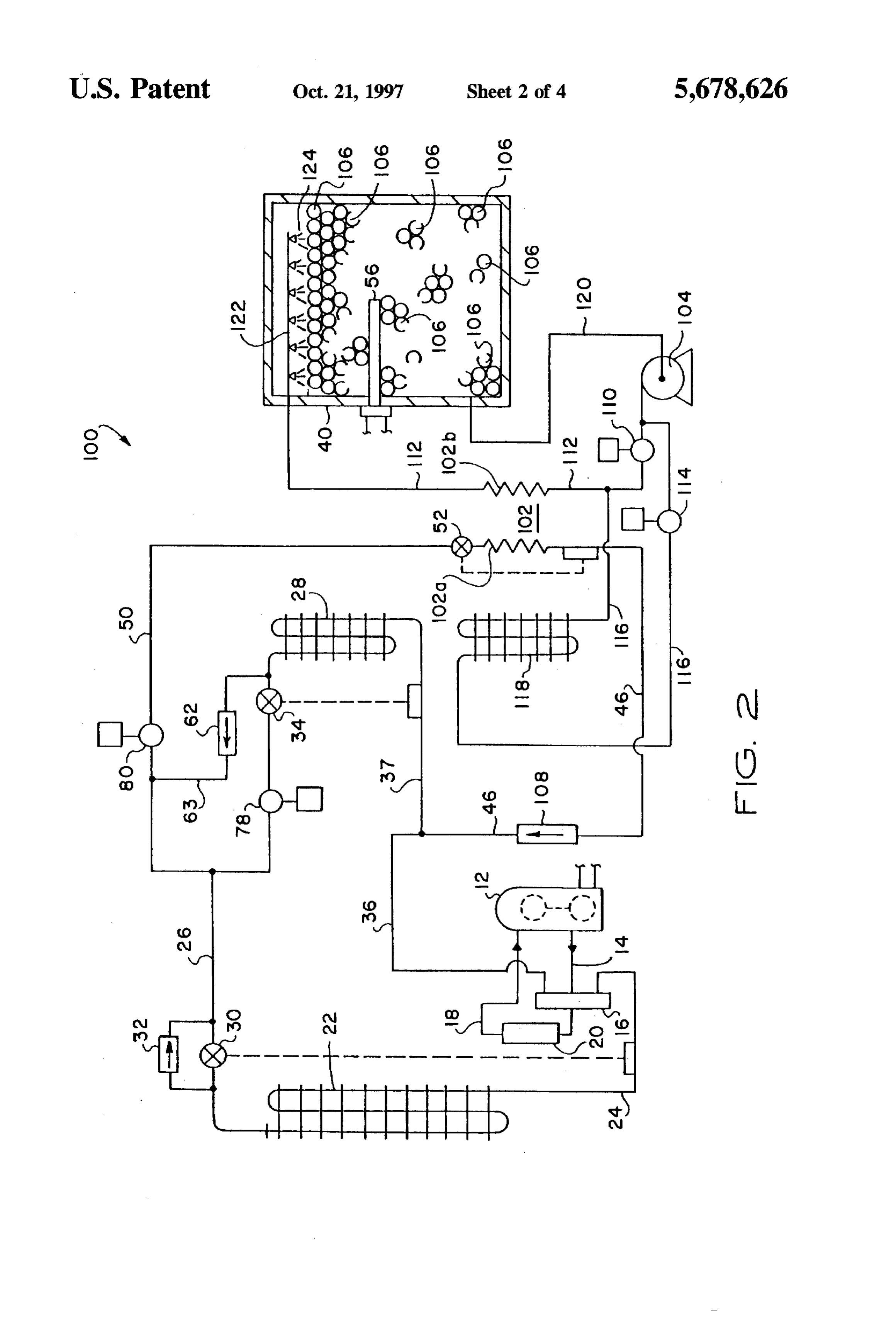
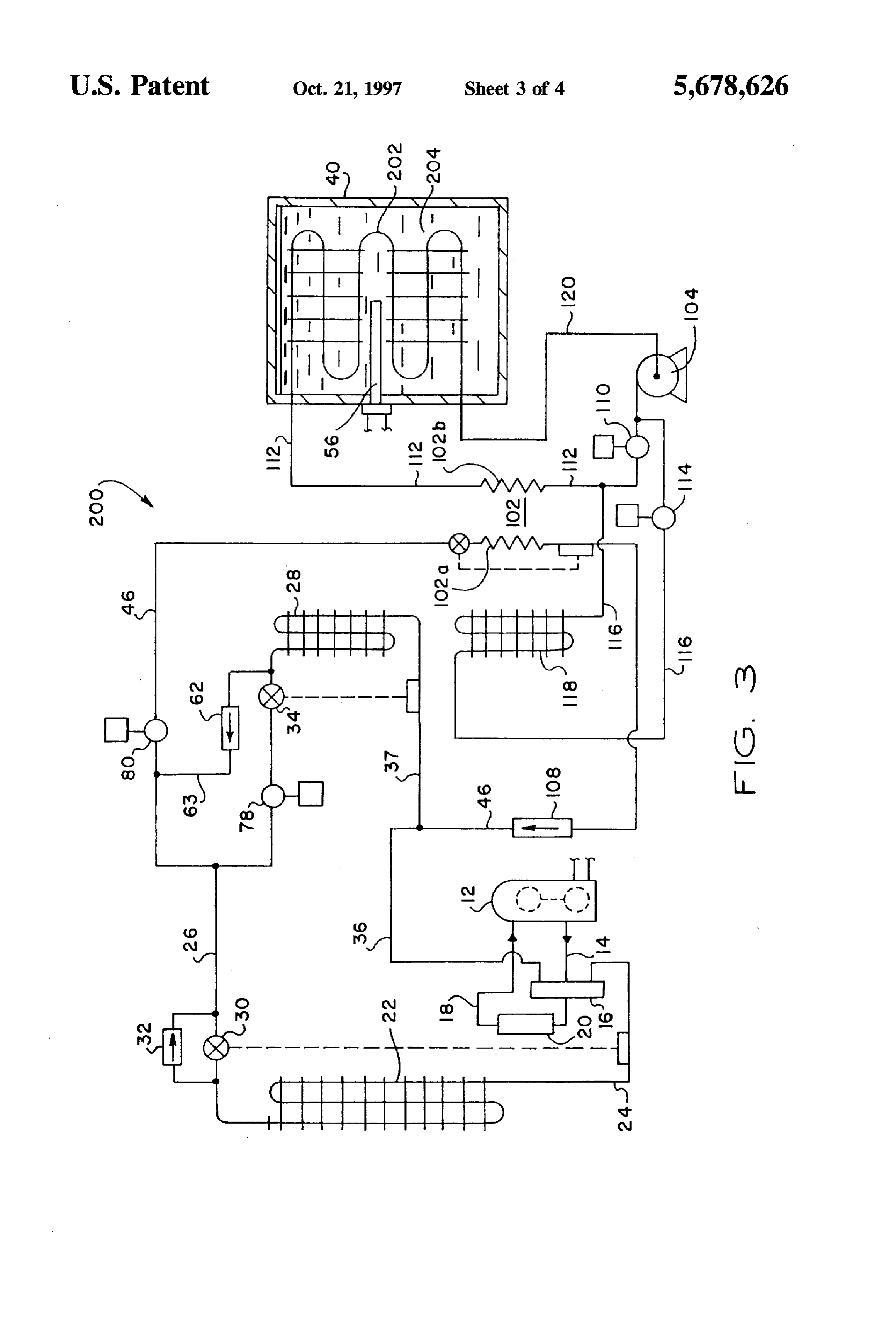
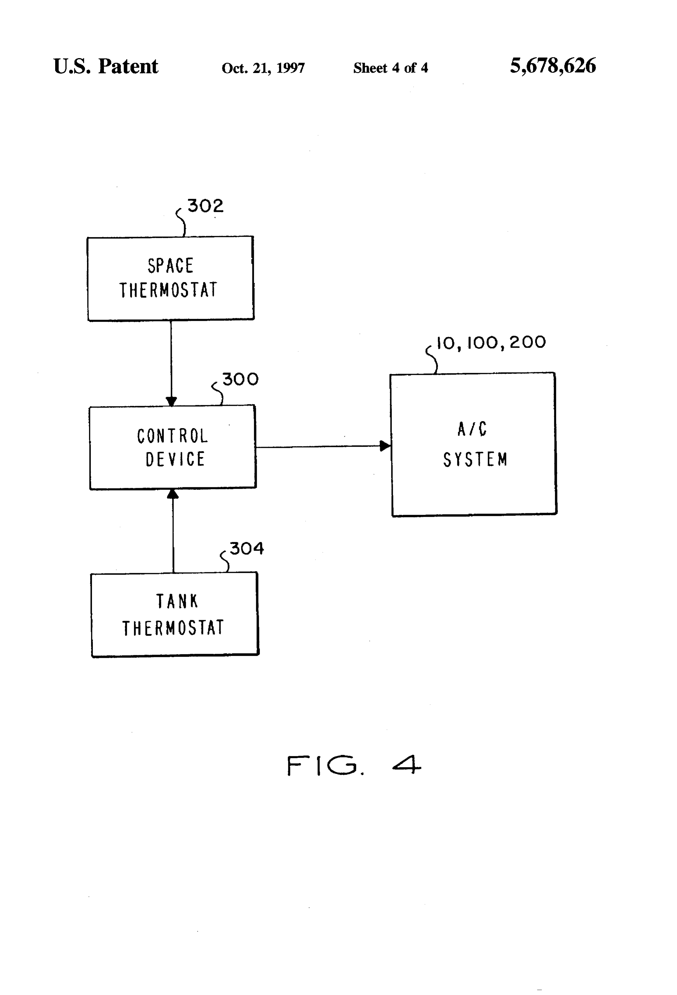
FIG. 1 is a schematic diagram of a first embodiment of an disposed within the tank 40. The heating element 56 may be air conditioning system of the present invention; a conventional electrical resistance heater operably con FIG. 2 is a schematic diagram of a second embodiment of nected to a source of electrical power (not shown). The an air conditioning system of the present invention; conduit 50 is connected to the conduit 26 and has interposed FIG. 3 is a schematic diagram of a third embodiment of therein a refrigerant liquid storage vessel 60 for storing an air conditioning system of the present invention; and excess refrigerant during certain operating modes of the FIG. 4 is an simplified block diagram illustrating control system 10. A suitable by-pass-type check valve 62 is inter of the air conditioning system of the present invention, 45 posed in a conduit 63 interconnecting the conduit 26 and the conduit 50 as illustrated. The compressor 12, heat exchanger
BEST MODE FOR CARRYING OUT THE 22, conduits 26 and 50, heat exchanger 44 and conduits 46 INVENTTON and 36 form a second refrigerant circuit of the system 10. The system 10 still further includes a liquid circulation
In the description which follows, like elements are pump 64 operably connected to the conduit 48 by a four-way marked throughout the specification and drawing with the SO reversing valve 66, which may be similar in some respects same reference numerals, respectively. The drawing figure is to the reversing valve 16 but is preferably provided with a not to scale and most of the elements are shown in schematic solenoid operator 67 for shifting the valve to provide fluid form in the interest of clarity and conciseness. flow in the directions to be described herein. The four-way Referring to FIG. 1, there is illustrated in schematic form valve 66 is also connected to a conduit 68, which is in an improved air conditioning (cooling and heating) system 55 communication with a fourth heat exchanger 70 (also a in accordance with the invention and generally designated refrigerant-to-air heat exchanger), which is located indoors by the numeral 10. The system 10 is adapted to operate with in heat exchange relationship with the space to be condi conventional refrigerant fluids used for commercial and tioned and is operable to provide cooling or heating of air residential cooling systems. The system 10 includes a motor passing thereover, in a conventional manner. The pump 64 driven compressor 12, connected to a compressed gas dis has an inlet or suction conduit 65 and discharge conduit 69 charge line 14, which is connected to a conventional four suitably connected to the valve 66. The heat exchanger 70 is way reversing valve 16. The compressor 12 also has a in communication with the conduits 36, 46, by way of a low-pressure vapor or gaseous refrigerant fluid suction or suitable connecting conduit 72. As previously &scribed, the inlet line 18 which is connected to the reversing valve 16 by conduit 36 is also in communication with the heat exchanger way of a conventional suction line accumulator 20. A first 65 28 by connecting conduit 37 and with the heat exchanger 44 refrigerant-to-air heat exchanger 22 (which is preferably in the tank 40 by way of the conduit 46, as illustrated. A short located outdoors) is suitably connected to the reversing portion 71 of conduit 68 may comprise a capillary tube
Page 8
expansion device or a conventional thermostatic expansion demand periods wherein so-called ice-making is provided device and bypass valve may be interposed in conduit 71. for the phase change material 42 which is converted from a The system 10 is also provided with four on-off-type liquid to a solid, for example. In operating mode 1, the solenoid operated valves 76, 78, 80 and 82. The valves 80 compressor 12 is operating, the heating element 56 is not and 82 are interposed in the conduit 50 on opposite sides of 5 operating, the pump 64 is not operating, the solenoid valve the liquid refrigerant storage vessel 60 while the valve 76 is 78 is closed and solenoid valves 76, 80 and 82 are open. interposed in the conduit 46 between the conduit 72 and the Compressed gas refrigerant leaves the compressor 12 and conduits 36, 37. The solenoid valve 78 is interposed in the flows through the reversing valve 16 and conduit 24 to heat conduit 26 between the expansion device 30 and the expan exchanger 22, which operates as a condenser. The con sion device 34. The heat exchanger 44, pump 64, valve 66, densed refrigerant flows through the bypass valve 32, con heatexchanger 70 and connecting conduits 48,65, 68, 69,72 duits 26 and 50, the expansion device 52 and into the heat and 46 form a third refrigerant circuit. exchanger coil 44, which operates as an evaporator. The system 10 may utilize several conventional elements Refrigerant, of course, leaves the expansion device 52 at a which have been previously described in somewhat general reduced pressure and cools the phase change material, such terms. The compressor 12 may be a conventional motor as water, 42 in the tank 40. Evaporated refrigerant is pulled driven compressor of a type well known for use in vapor 15 back through conduit 46, valve 76 and conduit 36 to the compression refrigeration or air conditioning systems. In compressor 12 by way of the reversing valve 16. During this like manner, the reversing valve 16 may be conventional and operating mode, some excess liquid refrigerant is stored in the expansion devices 30, 34 and 52 may be conventional storage vessel 60.
superheat controlled expansion devices, as illustrated. Heat Operating mode 2 is sometimes known as first-stage exchanger 22 may be an outdoor refrigerant-to-air heat 20 direct cooling and is characterized by operation of the exchanger, such as a serpentine coil having suitable finned compressor 12 to deliver high pressure gaseous refrigerant heat exchange surfaces and operable to have air circulated by way of the reversing valve 16 and the conduit 24 to the thereover by a suitable motor-driven fan (not shown). Heat exchanger 22 may also be of a type which is in communi 25 densedexchanger heat 22, which operates as a condenser. Con refrigerant flows through the by-pass valve 32 to heat cation with anotherheat source or heatsink (not shown). The exchanger 28, which heat exchangers 28 and 70 may be conventional indoor air Accordingly, valve 78is now operating as an evaporator coil. evaporator coil-type heat exchangers, wherein air is circu device 34 is operable to reduceand is open the the thermal expansion pressure of the liquid lated thereover by suitable fans (also not shown). The refrigerant as it enters the heat exchanger 28. Evaporated insulated tank 40 may be of generally conventional con 30 refrigerant returns to the compressor via conduits struction for pressure vessels and the serpentine coil-type valve 16. In the direct cooling operating mode 2, 37.36 valves and
heat exchanger 44 disposed therein may also be of generally 80 and 82 are closed and neither the pump 64 northe heating conventional construction. The pump 64 should be of a type which is adapted to pump a mixed phased fluid, gas and element 56 are in operation during the steady state portion liquid, without potential for damage to the pump. Certain 35 of the direct cooling operating mode. In the direct cooling mode 2, the system 10 is operating at approximately one types of rotary vane or helical screw-type pumps may be half of its total cooling capacity. utilized for the pump 64. A third operating mode, designated as mode 3, and also The modes of operation of the system 10 will now be known as first-stage shift cooling is carried out by shutting described in conjunction with Table I, which indicates the down the compressor 12 and starting the pump 64 while operating condition of certain elements of the system includ closing valves ing the compressor 12, the heating element 56, the pump 64, four-way valve 76, 66 78 and 80 and opening valve 82. The is positioned such that liquid refrigerant and the solenoid valves 76, 78, 80 and 82. will move from pump 64 through conduit 68, the heat TABLE exchanger 70, the conduit 72, the conduit 46 and the heat exchanger 44 back to the pump. Refrigerant is drawn out of
Item 45 the heat exchanger 44 by way of the con&it 48 and the four-way valve 66 to the pump inlet by way of conduit 65.
Mode 12 56 64 76 78 80 82 Solenoid valve 82 is left open only long enough to draw 1. O O O 1. 1. sufficient refrigerant into the heat exchanger 44 to provide a 2 1. O O O 1. O O full charge of refrigerant to circulate in the manner just
described. As refrigerant passes through the heat exchanger 5 O O O O O O 70, it evaporates and returns to the heat exchanger 44 where 6 1. OW O O O O O the low temperature of the medium 42 will cause the 7 O O 1. O O O O refrigerant to again condense into liquid form for circulation
O by the pump 64. The capacity of the system 10, in the
PO O O 1. O 1. O 55 operating mode 3, usually may be the same as in operating mode 2. However, an important advantage of operating mode 3 is that the power required for operating the pump 64
The operating modes are indicated as nos. 1 through 8, is on the order of 10-20% of the power required to operate and two temporary modes are indicated and designated the compressor 12. Heat exchanger 70 operates as an evapo hypermigration (HM) and pumpout (PO). A '0' in regard to rator and heat exchanger 44 operates as a condenser in an operating mode of a particular element indicates that the operating mode 3. Storage vessel 60 has sufficient storage element is in a closed, off or de-energized condition and a capacity to store the amount of refrigerant required to "1" in regard to a particular operating mode indicates that support mode 3 operation.
the element is in an open, on or energized condition, In order to pass from operating too& 2 to operating mode respectively. 65 3, also known as the shift cooling mode, the system 10 Operating mode 1 is typically a summertime or hot operates in a transition mode known as hypermigration weather mode of operation during off-peak electrical (HM). The hypermigration cycle usually takes a relatively
Page 9
short time, about three to five minutes, in a system having The system 10 may be operated in mode 6, also known as about 10 tons cooling capacity. In the hypermigration mode, the direct heating mode, while operating in mode 5 or not the heat exchanger 44 is utilized as a heat sink at about 32° operating in mode 5, as the choice may be. In the direct F., or at the freezing point of the phase change medium 42 heating mode 6, the compressor 12, reversing valve 16, heat if it is other than fresh water. Refrigerant fluid in the heat 5 exchanger 22 and heat exchanger 28 are operated in the exchanger 44 condenses and the pressure within the system manner of a conventional heat pump. In other words, the 10 decreases. Since refrigerant fluid throughout the rest of reversing valve 16 is positioned such that high pressure the system 10 is at a much higher pressure and temperature, refrigerant gas discharged from the compressor 12 passes arefrigerant fluid charge is drawn into the heat exchanger 44 through conduit 36, conduit 37 and gives up heat to the during the hypermigration mode. Table I shows the operat 10 medium passing over the heat exchanger 28, which now ing condition of the items listed during hypermigration. operates as a condenser, to condense the refrigerant, which The system 10 is advantageously operable to accept a then flows as a liquid through check valve 62 and conduit 26. cooling load that requires the compressor 12, heat exchanger The thermostatic expansion device 30 reduces the pressure 22 operating as a condenser and heat exchanger 28 operating of the refrigerant as it passes through heat exchanger 22, as an evaporator in the same manner as in mode 2, while 15 now operating as an evaporator. Gaseous refrigerant leaving simultaneously operating the thermal energy storage tank 40 in conjunction with heat exchanger 70 operating as an the and heat exchanger 22 passes through the reversing valve 16 into the compressor 12 inlet by way of conduit 18.
evaporator and heat exchanger 44 operating as a condenser in the same manner as in mode 3. Accordingly, a full load of An mode alternative heating mode 7 may be carried out in place 6, referring to Table I, wherein the compressor 12 capacity mode 4 operating condition may be sustained by the system 10. When transitioning from the so-called shift is in an off condition and the heating element 56 is cooling mode 3 to the full load capacity mode 4 or when de-energized while the pump 64 is energized to circulate starting full load capacity mode 4 with a sufficient charge of refrigerant fluid between the heat exchanger 70 and the heat ice or solid phase condition of the medium 42, mode PO is exchanger 44. In operating mode 7, which may also be carried out wherein valves 78 and 82 are closed, valves 76 designated as first stage shift heating, the electrical power and 80 are open and compressor 12 is operated to pull liquid 25 requirement of system 10 is only that which is required to refrigerant into receiver vessel 60 and heat exchanger 22. circulate the refrigerant fluid with the pump 64, that is on the Compressor 12 is operated until the compressor suction order of 10% to 20% of the power requirements of the pressure reaches a predetermined valve (e.g., 20 psig). At compressor 12. In heating mode 7, refrigerant fluid is drawn this time, mode PO is concluded and the system is operable from the heat exchanger 70, through the conduit 68 to the in mode 4. 30 valve 66 which has been positioned to provide for the In mode 4, valve 80 is closed while valves 78 and 82 are conduit 68 to be in communication with the inlet of pump opened and valve 76 is closed. The pump 64 is started to 64. This position of valve 66 places the conduit 48 in circulate refrigerant through the heat exchanger 70 and the communication with the heat exchanger 44 so that liquid heat exchanger 44 to provide cooling effect to air passing refrigerantenters the heat exchanger 44 and is evaporated by over the heat exchanger 70. The compressor 12 is operated 35 the heated material 42. Hot gaseous refrigerant leaves the in a conventional manner to pump refrigerant through the heat exchanger 44 and flows through conduit 46 and through reversing valve 16, conduit 24, heat exchanger 22 and the heat exchanger 70, which now operates as a condenser, through the heat exchanger 28 to cool air passing over heat by way of conduit 72, whereupon the fluid condenses back exchanger 28. Table I also shows the operating condition of to liquid form and is again circulated by the pump 64. the various elements in the full load capacity mode 4. The Assuming 90° F of usable heat storage in the tank 40, the system 10 may, of course, be operated in the full load cool storage to heat storage ratio of the thermal energy capacity mode 4 until all of the ice in the tank 40 is melted storage unit is about 1.33.
or the medium 42, if other than fresh water, has changed its A final operating mode of the system 10 is that wherein, phase from solid to liquid and the temperature of the liquid essentially, modes 6 and 7 are carried out simultaneously as has begun to rise sufficiently that heat exchanger 70 is no 45 mode 8. That is, the compressor 12 is operated in the heat longer effecting sufficient cooling to meet the load require pump mode to supply hot gaseous refrigerant fluid to the ments. In mode 4, heat exchangers 28, 70 provide a dual heat exchanger 28 and the pump 64 is operating to circulate evaporator capability for simultaneous operation of com refrigerant fluid through the tank 40 and to the heat pressor 12 and pump 64, whereby direct cooling and shift exchanger 70 in a hot gaseous form. Placing the system 10 cooling are operated in parallel. in condition to operate in modes 6, 7 or 8 may require brief The system 10 is also advantageously operable to provide operation in the hypermigration or pump-out mode to place for heating indoor air or the load associated with the heat a sufficient charge of refrigerant in the respective circuits exchangers 28 and 70. The various operating con&ions or which are operable in modes 6, 7 and 8. In mode 8, heat modes in which the system 10 may be operated to provide exchangers 28, 70 provide a dual condenser capability for heat at the heat exchangers 28 and 70 will now be described. 55 simultaneous operation of compressor 12 and pump 64, The first heating mode is designated as mode 5 and is that whereby direct heating and shift heating are operated in in which, during off-peak electricity demand periods, the parallel.
heating element 56 is used to heat the phase change material Referring to FIG. 2, a second embodiment of an air or medium 42 to a suitable temperature. For example, if the conditioning system according to the present invention, material 42 is fresh water, the heating element 56 may be generally designated by the numeral 100, is depicted. Sys operated to heat the water to a temperature in the range of tem 100 has a similar configuration to system 10, described 180°F to 190°F. In this operating condition, any refrigerant hereinabove with reference to FIG. 1, the primary difference in the heat exchanger 44 and the conduits connected thereto being that system 100 includes a heat exchanger 102 which will tend to migrate to the heat exchanger 70. Typically, in is external to storage tank 40, instead of a heat exchanger 44 operating mode 5, the valves 76, 78, 80 and 82 are closed, 65 (FIG. 1) which is immersed in the storage medium within the compressor 12 is in an off condition and the pump 64 is tank40, and a pump 104 suitable for pumping a substantially in an off condition. incompressible liquid refrigerant instead of pump 44, which
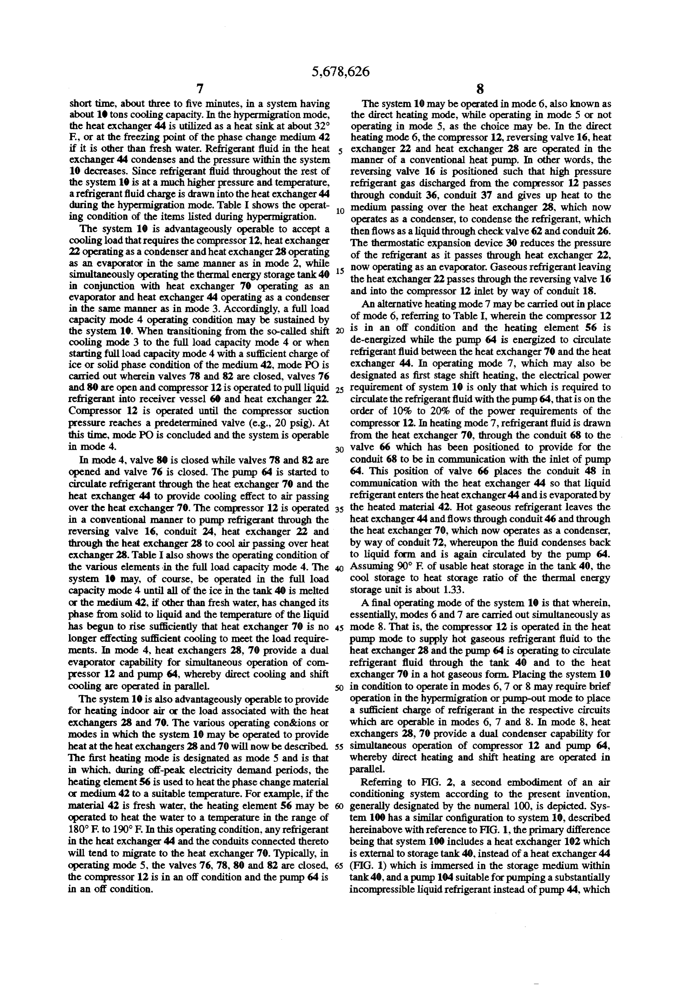
Page 10
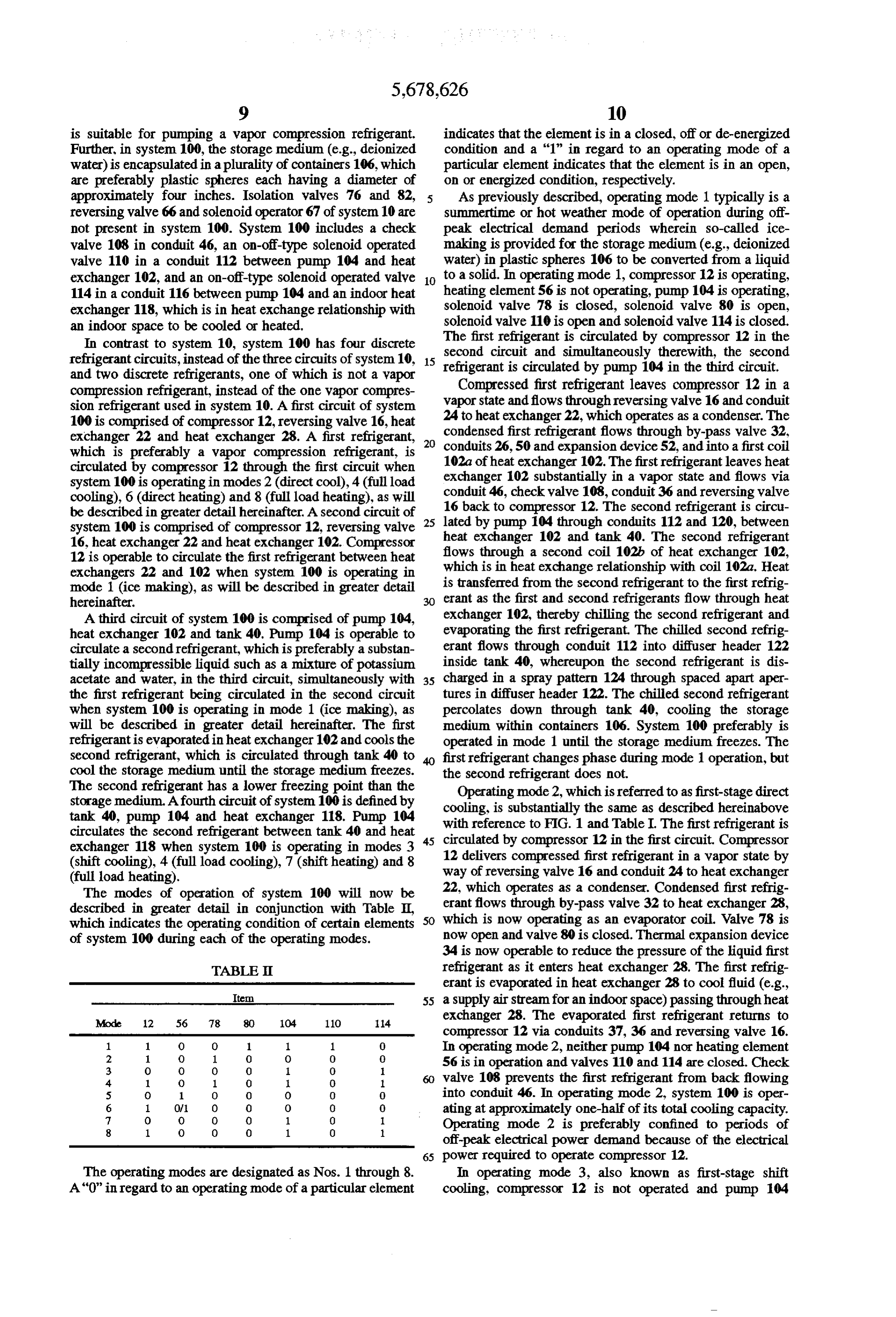
is suitable for pumping a vapor compression refrigerant. indicates that the element is in a closed, off or de-energized Further, in system 100, the storage medium (e.g., deionized condition and a "1" in regard to an operating mode of a water) is encapsulated in a plurality of containers 106, which particular element indicates that the element is in an open, are preferably plastic spheres each having a diameter of on or energized condition, respectively.
approximately four inches. Isolation valves 76 and 82, 5 As previously described, operating mode 1 typically is a reversing valve 66 and solenoid operator 67 of system 10 are summertime or hot weather mode of operation during off not present in system 100. System 100 includes a check peak electrical demand periods wherein so-called ice valve 108 in conduit 46, an on-off-type solenoid operated making is provided for the storage medium (e.g., deionized valve 110 in a conduit 112 between pump 104 and heat water) in plastic spheres 106 to be converted from a liquid exchanger 102, and an on-off-type solenoid operated valve 10 to a solid. In operating mode 1, compressor 12 is operating, 114 in a conduit 116 between pump 104 and an indoor heat heating element 56 is not operating, pump 104 is operating, exchanger 118, which is in heat exchange relationship with solenoid valve 78 is closed, solenoid valve 80 is open, an indoor space to be cooled or heated, solenoid valve 110 is open and solenoid valve 114 is closed. In contrast to system 10, system 100 has four discrete The first refrigerant is circulated by compressor 12 in the second circuit and simultaneously therewith, the second refrigerant circuits, instead of the three circuits of system 10, 15 refrigerant is circulated by pump 104 in the third circuit. and two discrete refrigerants, one of which is not a vapor Compressed first refrigerant leaves compressor 12 in a compression refrigerant, instead of the one vapor compres vapor state and flows through reversing valve 16 and conduit sion refrigerant used in system 10. A first circuit of system 24 to heat 100 is comprised of compressor 12, reversing valve 16, heat condensedexchanger 22, which operates as a condenser. The first refrigerant flows through by-pass valve 32, exchanger 22 and heat exchanger 28. A first refrigerant, 20 which is preferably a vapor compression refrigerant, is conduits 26, 50 and expansion device 52, and into a first coil circulated by compressor 12 through the first circuit when 102a of heat exchanger 102. The first refrigerant leaves heat system 100 is operating in modes 2 (direct cool), 4 (full load exchanger 102 substantially in a vapor state and flows via cooling), 6 (direct heating) and 8 (full load heating), as will conduit 46, check valve 108, conduit 36 and reversing valve be described in greater detail hereinafter. A second circuit of 25 16 back to compressor 12. The second refrigerant is circu system 100 is comprised of compressor 12, reversing valve lated by pump 104 through conduits 112 and 120, between 16, heat exchanger 22 and heat exchanger 102. Compressor heat exchanger 102 and tank 40. The second refrigerant 12 is operable to circulate the first refrigerant between heat flows through a second coil 102h of heat exchanger 102, exchangers 22 and 102 when system 100 is operating in which is in heat exchange relationship with coil 102a. Heat mode 1 (ice making), as will be described in greater detail is transferred from the second refrigerant to the first refrig hereinafter. erant as the first and second refrigerants flow through heat A third circuit of system 100 is comprised of pump 104, exchanger 102, thereby chilling the second refrigerant and heat exchanger 102 and tank 40. Pump 104 is operable to evaporating the first refrigerant. The chillied second refrig circulate a second refrigerant, which is preferably a substan erant flows through conduit 112 into diffuser header 122 tially incompressible liquid such as a mixture of potassium inside tank 40, whereupon the second refrigerant is dis acetate and water, in the third circuit, simultaneously with 35 charged in a spray pattern 124 through spaced apart aper the first refrigerant being circulated in the second circuit tures in diffuser header 122. The chilled second refrigerant when system 100 is operating in mode 1 (ice making), as percolates down through tank 40, cooling the storage will be described in greater detail hereinafter. The first medium within containers 106. System 100 preferably is refrigerantis evaporated in heat exchanger 102 and cools the operated in mode 1 until the storage medium freezes. The second refrigerant, which is circulated through tank 40 to first refrigerant changes phase during mode 1 operation, but cool the storage medium until the storage medium freezes. the second refrigerant does not.
The second refrigerant has a lower freezing point than the Operating mode 2, which is referred to as first-stage direct storage medium. Afourth circuit of system 100 is defined by cooling, is substantially the same as described hereinabove tank 40, pump 104 and heat exchanger 118. Pump 104 with reference to FIG. 1 and Table I. The first refrigerant is circulates the second refrigerant between tank 40 and heat 45 circulated by compressor 12 in the first circuit. Compressor exchanger 118 when system 100 is operating in modes 3 12 delivers compressed first refrigerant in a vapor state by (shift cooling), 4 (full load cooling), 7 (shiftheating) and 8 (full load heating). way of reversing valve 16 and conduit 24 to heat exchanger The modes of operation of system 100 will now be 22, which operates as a condenser. Condensed first refrig described in greater detail in conjunction with Table II, erant flows through by-pass valve 32 to heat exchanger 28, which indicates the operating condition of certain elements 50 which is now operating as an evaporator coil. Valve 78 is of system 100 during each of the operating modes. now open and valve 80 is closed. Thermal expansion device 34 is now operable to reduce the pressure of the liquid first
TABLE refrigerant as it enters heat exchanger 28. The first refrig erant is evaporated in heat exchanger 28 to cool fluid (e.g.,
Item 55 a supply air stream for an indoor space) passing through heat
exchanger 28. The evaporated first refrigerant returns to compressor 12 via conduits 37, 36 and reversing valve 16.
In operating mode 2, neither pump 104 nor heating element
56 is in operation and valves 110 and 114 are closed. Check 4 O 1 O O 1. valve 108 prevents the first refrigerant from back flowing 5 O 1. O O O O O into conduit 46. In operating mode 2, system 100 is oper
O ating at approximately one-half of its total cooling capacity.
Operating mode 2 is preferably confined to periods of off-peak electrical power demand because of the electrical 65 power required to operate compressor 12.
The operating modes are designated as Nos. 1 through 8. In operating mode 3, also known as first-stage shift A "0" in regard to an operating mode of a particular element cooling, compressor 12 is not operated and pump 104
Page 11
circulates the second refrigerant in the fourth circuit. In this respect to FIG. 1. During off-peak electricity demand mode of operation, the second refrigerant flows between periods, heating element 56 is used to heat the second tank 40 and heat exchanger 118 via conduits 120, 116 and refrigerant in tank 40. The second refrigerant in tank 40 112. The second refrigerant is chilled by the storage medium heats the storage medium encapsulated in containers 106 to as it percolates down through tank 40 and cools fluid (e.g., a suitable temperature. For example, if the storage medium indoor supply air) passing through heat exchanger 118 as the is deionized water, heating element 56 may be operated to chilled second refrigerant flows through heat exchanger 118. heat the water to a temperature in the range of 180° F to In mode 3, valve 110 is closed to prevent the second and 190°F. Typically, in operating mode 5, valves 78, 80, 110 refrigerant from flowing through heat exchanger 102 and 114 are closed, compressor 12 is in an off condition and value 114 is open to allow the second refrigerant to flow 10 pump thermal 104 is in an off condition. During mode 5, warm energy storage is effected.
through heat exchanger 118.
The capacity of system 100 in operating mode 3, usually System 100 may be operated in mode 6, also known as the may be the same as in operating mode 2. However, an direct heating mode, either while still operating in mode 5 or not operating therein, as the case may be. In mode 6, the first important advantage of operating mode 3 is that the power refrigerant is circulated in the first circuit, but in an opposite required for operating pump 104 is on the order of 10-20% 15 direction from of the power required to operate compressor 12. Therefore, effect heat pumptheoperation. direction of circulation in mode 2, to operating mode 3 is advantageous during periods of peak 16, heat exchanger 22, and Compressor 12, reversing valve heat exchanger 28 are operated electrical power demand. in the manner of a conventional heat pump. Reversing valve One skilled in the art will recognize that it is not necessary 20 16 is positioned such that the first refrigerant discharged in to operate system 100 in the hypermigration (HM) mode a vapor state at high pressure from compressor 12 passes described hereinabove with reference to FIG. 1 when tran through conduits 36, 37 and gives up heat to the fluid (e.g., sitioning between operating modes 2 and 3 because the first indoor supply air) passing through heat exchanger 28, which and fourth circuits are isolated from each other and each now operates as a condenser to condense the first refrigerant, circuit has its own discrete refrigerant. Specifically, the first 25 thereby heating the fluid passing through heat exchanger 28. refrigerant, which is a vapor compression fluid and changes The condensed first refrigerant then flows through check phase in mode 2 operation, is circulated in the first circuit valve 62 and conduit 26. Thermal expansion device 30 while the second refrigerant, which is a substantially incom reduces the pressure of the first refrigerant as it passes pressible liquid and does not change phase in mode 3 through heat exchanger 22, now operating as an evaporator. operation, is circulated in the fourth circuit. 30 The vaporized first refrigerant leaving heat exchanger 22 In operating mode 4, the first refrigerant is circulated in passes through reversing valve 16 and into compressor 12 by the first circuit simultaneously with the second refrigerant way of conduit 18, System 100 is typically operated in mode being circulated in the fourth circuit. Operating mode 4 is 6 during off-peak electrical demand periods. essentially simultaneous operation of modes 2 and 3 to During peak electrical demand periods, itis advantageous achieve full load capacity. In mode 4, valves 80 and 110 are 35 to provide heating by operating system 100 in mode 7 closed and valves 78 and 114 are open. As in mode 2, instead of mode 6. In mode 7, compressor 12 is in an off compressor 12 is operated to circulate the first refrigerant condition and heating element 56 is de-energized, while between heat exchanger 22 operating as a condenser and pump 104 is energized to circulate the second refrigerant heat exchanger 28 operating as an evaporator to cool fluid between heat exchanger 118 and tank 40. In operating mode (e.g., indoor supply air) passing through heat exchanger 28. 7, which is designated as first stage shift heating, the At the same time, pump 104 circulates the second refrigerant electrical power requirement of system 100 is only that between tank 40 and heat exchanger 118 with the cooling which is required to circulate the second refrigerant with capacity of the storage medium in tank 40 being used to chill the second refrigerant and provide cooling for the fluid (e.g., pump 104, that is on the order of 10-20% of the power requirements of operating compressor 12. In mode 7, the indoor supply air) passing through heat exchanger 118, 45 second refrigerant is circulated in the fourth circuit. Valves System 100 may be operated in the full load capacity mode 78, 80 and 110 are closed and valve 114 is open. The second until the storage medium encapsulated in containers 106 has refrigerantflows through conduits 120,116 and 112 between changed its phase from solid to liquid and the temperature of heat exchanger 118 and tank 40. The second refrigerant the liquid storage medium has begun to rise sufficiently that picks up heat from the heated storage medium and carries heat exchanger 118 is no longer effecting sufficient cooling the thermal energy to heat exchanger 118 wherein fluid (e.g., to meet the load requirements. In mode 4, indoor heat indoor supply air) passing through heat exchanger 118 is exchangers 28, 118 provide full capacity cooling for air heated.
Supplied to an indoor space. Compressor 12 and pump 104 Operating mode 8 is essentially simultaneous operation of are operated simultaneously, whereby the direct cooling and system 100 in mode 6 and mode 7. That is, compressor 12 shift cooling modes are operated in parallel. 55 is operated in the heat pump mode to supply a hot gaseous One skilled in the art will recognize that it is not necessary first refrigerant to heat exchanger 28 and pump 104 is to operate system 100 in the pumpout (PO) mode described operated to circulate the second refrigerant between tank 40 hereinabove with reference to FIG. 1, when transitioning and heat exchanger 118 to provide heated second refrigerant from mode 3 to mode 4 or when starting mode 4 for the same to heat exchanger 118. As previously described, it is not reason that the hypermigration (HM) mode is not necessary, necessary to operate system 100 in either the hypermigration as described hereinabove. or the pumpout mode prior to operating system 100 in either System 100 is also operable to provide for heating supply modes 6, 7 or 8. In mode 8, heat exchangers 28, 118 provide airfor an indoor space. The various operating conditions and full heating capacity of system 100, whereby direct heating modes in which system 100 may be operated to provide heat and shift heating are operated in parallel. at heat exchangers 28, 118 will now be described. 65 Referring to FIG. 3, a third embodiment of an air condi The first heating mode is designated as mode 5 and is tioning system according to the present invention is essentially the same as mode 5 described hereinabove with depicted. System 200 is substantially the same as system
Page 12
100, described hereinabove with reference to FIG. 2 and a thermal energy storage unit including a tank having a Table II, except that system 200 includes a fifth heat thermal energy storage medium disposed therein; exchanger 202, which is immersed in a thermal energy a third heat exchanger operably connected to said tank, storage medium 204 within tank 40. Storage medium 204 is said compressor and sail first heat exchanger, said a phase change material (e.g., water) having a higher freez compressor being operable to circulate the first refrig ing point than the second refrigerant. In system 200, storage erant between said first heat exchanger and said third material 204 is not encapsulated in containers as in system heat exchanger, whereby a second refrigerant in heat 100, but is rather constrained only by the shape of tank 40. exchange relationship with the first refrigerant in said System 200 is also operable in eight discrete modes as third heat exchanger is cooled, the second refrigerant depicted in Table II. Table II also shows the respective 10 being a substantially incompressible liquid; conditions of the various elements of system 200 in the eight a fourth heat exchanger operably connected to said third different operating modes. These conditions are the same as heat exchanger, said fourth heat exchanger being in in system 100 so that Table II is applicable to both the heat exchange relationship with the supply air stream; operation of system 100 and the operation of system 200. a refrigerant circulation device for circulating the second Heat exchanger 202 is preferably a coil comprising multiple refrigerant between said third heat exchanger and said passes through tank 40. Diffuser header 122 of system 100 15 tank, whereby the storage medium is cooled, said is not included in system 200. refrigerant circulation device being further operable to In operating mode 1 (ice making), the second refrigerant circulate the second refrigerant between said third heat cools storage medium 204 as the second refrigerant makes exchanger and said fourth heat exchanger, whereby the multiple passes through heat exchanger 202. In operating 20 supply air stream is cooled; and modes 3 and 4, the second refrigerant is cooled by storage a control device adapted to effect flow of the first refrig medium 204 as it makes multiple passes through heat erantthrough a first circuit comprising said compressor, exchanger 202. In operating modes 7 and 8, the second said first heat exchanger and said second heat refrigerant is heated by storage medium 204 as the second exchanger, and through a second circuit comprising refrigerant makes multiple passes through heat exchanger 25 said compressor, said firstheat exchanger and said third 202. heat exchanger, said flow control device being operable Referring to FIG. 4, one skilled in the art will recognize to effect flow of the second refrigerant through a third that each system 10, 100, 200 is provided with a suitable circuit comprising said third heat exchanger, said control device for sensing the load requirements of the refrigerant circulation device and said tank, and corresponding system 10, 100, 200 in both cooling and 30 through a fourth circuit comprising said third heat heating modes and for automatically controlling operation of exchanger, said refrigerant circulation device and said the corresponding system 10, 100, 200 to take advantage of fourth heat exchanger, said system being selectively off-peak electricity pricing whereupon the corresponding operable in a first operating mode wherein the first system 10, 100, 200 is operated in a selected mode which is refrigerant flows through said second circuit and the appropriate for peak or off-peak energy pricing, as well as 35 second refrigerant flows through said third circuit to for the heating or cooling load requirements. cool the storage medium, in a second operating mode wherein the first refrigerant flows through said first
Control device 300 receives various control inputs, such circuit to cool the supply air stream with said second as from an indoor space thermostat 302 and a tank thermo heat exchanger, in a third operating mode wherein the stat 304. Thermostat 302 indicates a demand for space second refrigerant flows through said fourth circuit to cooling or space heating when the space temperature rises cool the supply air stream with said fourth heat above or falls below a predetermined temperature setpoint. exchanger, and in a fourth operating mode wherein the Tank thermostat 304 senses the temperature of the storage first refrigerant flows through said first circuit and the medium in the thermal energy storage tank and control second refrigerant flows through said fourth circuit to device 300 uses this input to control the various modes of cool the supply air stream with both said second heat operation of the corresponding system 10, 100, 200. Control 45 exchanger and said fourth heat exchanger. device 300 may also receive other control inputs, such as 2. The system of claim 1 wherein the storage medium is signals from a local utility. water and the second refrigerant is a liquid having a lower Although various embodiments of the invention have freezing point than the storage medium.
been described in detail herein, those skilled in the art will 3. The system of claim 1 wherein the storage medium is also recognize that various substitutions and modifications 50 deionized water encapsulated in a plurality of containers may be made to the above-described embodiments without within said tank.
departing from the scope and spirit of the invention, as 4. The system of claim 1 wherein said third heat recited in the appended claims. exchanger is external to said tank, said system further I claim: including a fifth heat exchanger immersed in the storage 1. An air conditioning system, comprising: 55 medium within said tankfor effecting heat transfer between a compressor for compressing a first refrigerant, the first the second refrigerant and the storage medium. refrigerant being a compressible phase change fluid; 5. The system of claim 1 further including flow reversing a first heat exchanger operably connected to said com means operably connected to said compressor for reversing pressor; - the flow of the first refrigerant in said first circuit to provide a second heat exchanger operably connected to said first heated first refrigerant to said second heat exchanger for heat exchanger and to said compressor, said second heating the supply air stream with said second heat heat exchanger being in heat exchange relationship exchanger when the first refrigerant flows through said first with a supply air stream for an indoor space, said circuitin one direction and to provide cooled first refrigerant compressor being operable to circulate the first refrig to said second heat exchanger for cooling the supply air erant between said first heat exchanger and said second 65 stream with said second heat exchanger when the first heat exchanger, whereby the supply air stream is refrigerant flows through said first circuit in an opposite cooled; direction.
Page 13
6. The system of claim 1 further including a heating 13. The system of claim 9 further including a heating device for heating the storage medium to provide heated device for heating the storage medium to provide heated second refrigerant in said fourth circuit for heating the second refrigerant in said fourth circuit for heating the supply air stream with said fourth heat exchanger when the supply air stream with said fourth heat exchanger when the second refrigerant flows through said fourth circuit. second refrigerant flows through said fourth circuit. 7. The system of claim 1 further including at least one 14. The system of claim 9 further including at least one isolation valve interposed in said system for isolating said isolation valve interposed in said system for isolating said third circuit from said fourth circuit. third circuit from said fourth circuit. 8. The system of claim 1 wherein said third heat water 15. The system of claim 9 wherein the storage medium is exchanger is external to said tank. 10 and the second refrigerant is a liquid having a lower 9. An air conditioning system comprising: freezing point than the storage medium.
a compressor, a first heat exchanger and a second heat deionized water The system of claim 9 wherein the storage medium is encapsulated in a plurality of containers exchanger operably interconnected to define a first within said tank.
circuit, said second heat exchanger being in heat 17. A method of operating the air conditioning system of exchange relationship with a supply air stream for an 15 claim 9 to reduce the consumption of electric power during indoor space; periods of peak power demand, said method comprising the a thermal energy storage unit including a tank containing steps of:
a thermal energy storage medium; circulating the first refrigerant through said second circuit a third heat exchanger operably interconnected with said 20 and the second refrigerant through said third circuit tank, said compresser and said first heat exchanger to during a period of non-peak power demand to cool the define a second circuit; storage medium; and a refrigerant circulation device operably interconnected circulating the second refrigerant through said fourth with said third heat exchanger and said tank to define circuit during a period of peak power demand to cool a third circuit; 25 the supply air stream with said fourth heat exchanger. a fourth heat exchanger operably interconnected with said 18. The method of operating the air conditioning system tank and said refrigerant circulation device to define a as set forth in claim 17, further including operating said fourth circuit, said fourth heat exchanger being in heat compressor to circulate the first refrigerant through the first exchange relationship with the supply air stream; and circuit while continuing to circulate the second refrigerant a control device adapted to selectively control operation 30 through the fourth circuit to cool the supply air stream with of said compressor to effect flow of a first refrigerantin said second and fourth heat exchangers simultaneously. said first circuit for cooling the supply air stream with claim19. A method of operating the air conditioning system of said second heat exchanger, to control said compressor 9 to provide heating, comprising heating the storage to effect flow of the first refrigerant in said second medium and circulating the second refrigerant through said circuit and said refrigerant circulation device to effect 35 fourthexchanger.
circuit to heat the supply air stream with said fourth flow of a second refrigerant in said third circuit simul heat taneously with the flow of the first refrigerant in said as 20. The method of operating the air conditioning system set forth in claim.19, further including circulating the first second circuit, whereby the second refrigerantis cooled by the first refrigerant and the storage medium is cooled refrigerant through said first circuit to condense the first by the second refrigerant, and to control said refrigerant refrigerant in said second heat exchanger and evaporate the circulation device to circulate the second refrigerant in first refrigerant in said first heat exchanger to heat the supply said fourth circuit for cooling the supply air stream with air stream with said second heat exchanger. said fourth heat exchanger, the first refrigerant being a 21. The method of operating the air conditioning system compressible phase change fluid and the second refrig as set forth in claim 20, including simultaneously circulating erant being a substantially incompressible liquid. 45 the first refrigerant in said first circuit and the second 10. The system of claim 9 wherein said control device is refrigerant in said fourth circuit to heat the supply air stream adapted to control said compressor and said refrigerant with said second and fourth heat exchangers. circulation device to simultaneously circulate the first refrig 22. The system of claim 9 wherein said third heat erant in said first circuit and the second refrigerant in said exchanger is external to said tank.
fourth circuit for cooling the supply air stream with both said 50 23. The system of claim 22 further including a fifth heat second heat exchanger and said fourth heat exchanger. exchanger immersed in the storage medium within said tank 11. The system of claim 9 wherein said first heat for effecting heat transfer between the second refrigerant and exchanger is an outdoor heat exchanger which is operable as the24.storage An medium.
air conditioning system comprising:
a condenser and said second and fourth heat exchangers are indoor heat exchangers operable as evaporators for cooling 55 a compressor, a first heat exchanger and a second heat the supply air stream. exchanger operably interconnected to define a first 12. The system of claim 9 further including flow reversing circuit, said second heat exchanger being in heat means operably connected to said compressor for reversing exchange relationship with a supply air stream for an the flow of the first refrigerant in said first circuit to provide indoor space;
heated first refrigerant to said second heat exchanger for a thermal energy storage unit including a tank containing heating the supply air stream with said second heat a thermal energy storage medium; exchanger when the first refrigerant flows through said first a third-heat exchanger external to said tank and operably circuit in one direction and to provide cooled first refrigerant interconnected with said tank, said compressor and said to said second heat exchanger for cooling the supply air first heat exchanger to define a second circuit; stream with said second heat exchanger when the first a refrigerant circulation device operably interconnected refrigerant flows through said first circuit in an opposite with said third heat exchanger and said tank to define direction. a third circuit;
Page 14
afourth heat exchanger operably interconnected with said 27. The system of claim 24 further including flow revers tank and said refrigerant circulation device to define a ing means operably connected to said compressor for revers fourth circuit, said fourth heat exchanger being in heat ing the flow of the first refrigerant in said first circuit to exchange relationship with the supply air stream; and provide heated refrigerant to said second heat exchanger for a control device adapted to selectively control operation heating the supply air stream with said second heat exchanger when the first refrigerant flows through said first of said compressor to effectflow of a first refrigerantin circuitin one direction and to provide cooled first refrigerant said first circuit for cooling the supply air stream with to said second heat exchanger for cooling the supply air said second heat exchanger, to control said compressor stream with said second heat exchanger when the first to effect flow of the first refrigerant in said second refrigerant flows through said first circuit in an opposite
circuit and said refrigerant circulation device to effect direction.
flow of a second refrigerant in said third circuit simul 28. The system of claim 24 further including a heating taneously with the flow of the first refrigerant in said device for heating the storage medium to provide heated second circuit, whereby the second refrigerantis cooled second refrigerant in said fourth circuit for heating the by the first refrigerant and the storage mediumis cooled supply air stream with said fourth heat exchanger when the by the second refrigerant, and to control said refrigerant 15 second refrigerant flows through said fourth circuit. circulation device to circulate the second refrigerant in 29. The system of claim 24 further including at least one said fourth circuit for cooling the supply air stream with isolation valve interposed in said system for isolating said said fourth heat exchanger. third circuit from said fourth circuit. 25. The system of claim 24 wherein said control device is 30. The system of claim 24 wherein the storage medium adapted to control said compressor and said refrigerant 20 is water and the second refrigerant is a liquid having a lower circulation device to simultaneously circulate the first refrig freezing point than the storage medium. erant in said first circuit and the second refrigerant in said 31. The system of claim 24 wherein the storage medium fourth circuit for cooling the supply air stream with both said is deionized water encapsulated in a plurality of containers second heat exchanger and said fourth heat exchanger. within said tank 26. The system of claim 24 wherein said first heat 25 32. The system of claim 24 further including a fifth heat exchanger is an outdoorheat exchanger which is operable as exchanger located within said tankfor effecting heat transfer a condenser and said second and fourth heat exchangers are between the second refrigerant and the storage medium. indoor heat exchangers operable to cool the supply air
Stream. ck is e :
Provenance
- Collection
- Cited prior art
- Original PDF
- patentimages.storage.googleapis.com →
- Filed
- 1995-11-17
- Pages
- 14
- Method
- pdftotext (the PDF's own text layer) + pdftoppm 300dpi page scans
- Source
- Google Patents bibliographic record
- Granted
- 1997-10-21
- Inventors
- Theodore C. Gilles; Lennox Industries Inc
- Transcribed from
- patentimages.storage.googleapis.com →