patent · US5438961
Method for operating a hydrogen engine, motor-vehicle drive
8 August 1995
Page 1 — bibliographic record
United States Patent (19) 11 Patent Number: 5,438,961 Peschka et al. 45 Date of Patent: Aug. 8, 1995 54 METHOD FOR OPERATING A HYDROGEN FOREIGN PATENT DOCUMENTS
ENGINE, MOTOR-VEHICLE DRIVE
75) Inventors: Walter Peschka, Sindelfingen; 0318904 6/1989 European Pat. Off. ... 123/DIG. 12
Gottfried Schneider, Stuttgart, both of Germany Primary Examiner-Henry C. Yuen
Assistant Examiner-Erick Solis 73) Assignee: Deutsche Forschungsanstalt fuer Attorney, Agent, or Firm-Barry R. Lipsitz Luftund Raumfahrt e.V., Bonn,
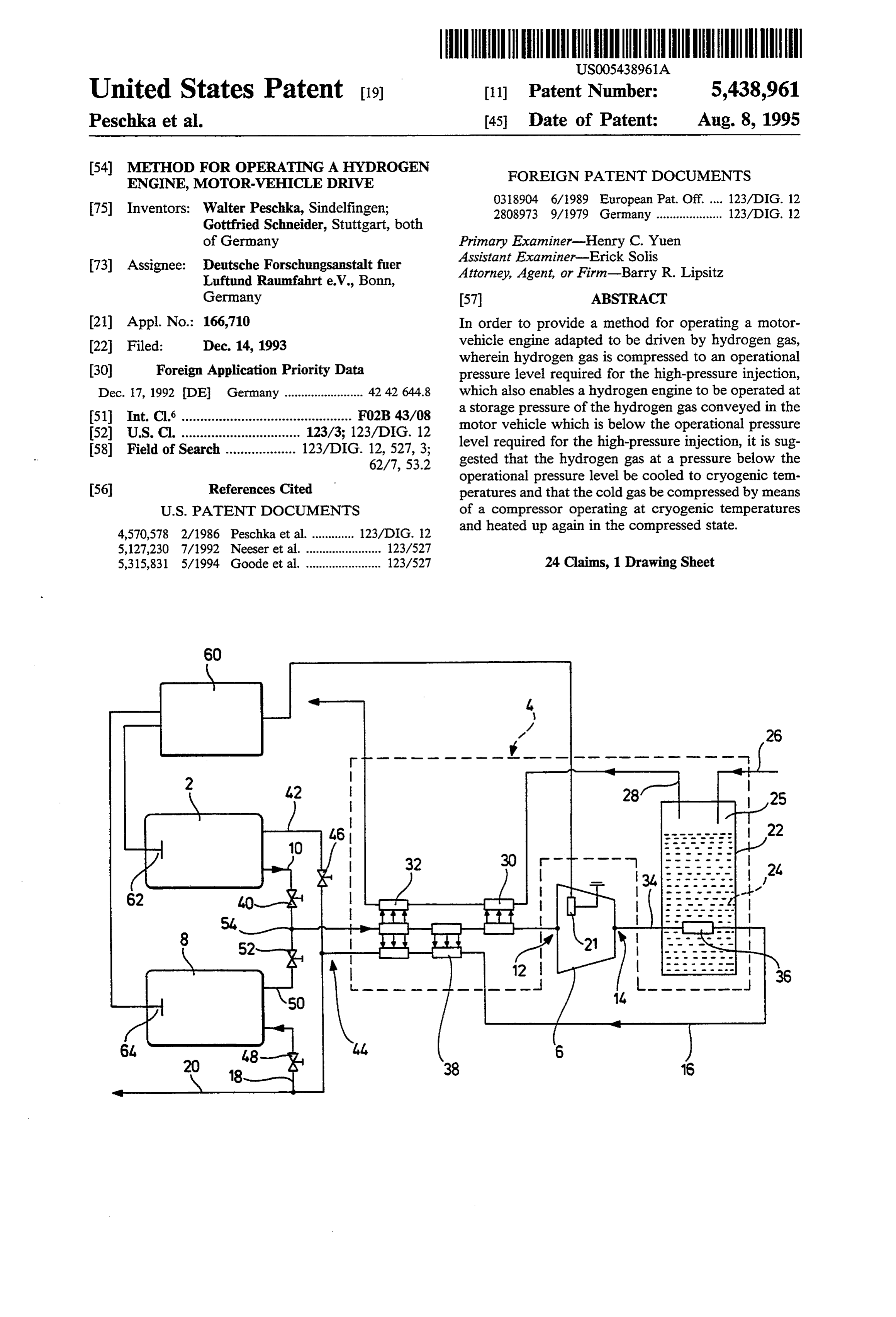
Germany 57 ABSTRACT (21) Appl. No.: 166,710 In order to provide a method for operating a motor (22 Filed: Dec. 14, 1993 vehicle engine adapted to be driven by hydrogen gas, wherein hydrogen gas is compressed to an operational 30 Foreign Application Priority Data pressure level required for the high-pressure injection, Dec. 17, 1992 DE Germany ........................ 42 42 644.8 which also enables a hydrogen engine to be operated at 51) Int. Cl' .............................................. FO2B 43/08 a storage pressure of the hydrogen gas conveyed in the 52 U.S.C. ................................ 123/3; 123/DIG. 12 motor vehicle which is below the operational pressure 58) Field of Search ................... 123/DIG. 12, 527, 3; level required for the high-pressure injection, it is sug 62/7, 53.2 gested that the hydrogen gas at a pressure below the operational pressure level be cooled to cryogenic tem 56 References Cited peratures and that the cold gas be compressed by means
4,570,578 2/1986 Peschka et al. ............. 123/DIG. 12 and heated up again in the compressed state. 5,127,230 7/1992 Neeser et al. ....................... 123/527 5,315,831 5/1994 Goode et al. ....................... 123/527 24 Claims, 1 Drawing Sheet
Page 2
Drawing sheet — no readable text.
Page 3
cal dimensions as well as the drive requirements of the
METHOD FOR OPERATING A HYDROGEN "cold' compressor can be reduced approximately by ENGINE, MOTOR-VEHICLE DRIVE the factor 4-5 in relation to a compressor operating at ambient temperature.
The invention relates to a method for operating a 5 Although the gas to be compressed can, within the motor-vehicle engine adapted to be driven with hydro meaning of the invention, be cooled in any optional gen gas, in which hydrogen gas is compressed to an manner, i.e., for example, by using any optional thermal operational pressure level required for the high-pres motor, it has proven to be particularly advantageous for sure injection. the hydrogen gas which is to be compressed to be In addition, the invention relates to a motor-vehicle 10 cooled by means of a cryogenic medium. A cryogenic drive comprising a hydrogen engine and a means for medium is to be understood in this respect as fundamen increasing the pressure of hydrogen gas conveyed in a tally any substance which is cooled to cryogenic tem first pressure-gas storage means to an operational pres peratures and suitable for the specific use, i.e., in partic sure level required for the high-pressure injection in the ular, liquid nitrogen or oxygen or liquid argon or their
The high-pressure injection in hydrogen-operated vapors. In view of the heavy and voluminous pressure-gas motor vehicle engines is necessary for achieving the storage engine characteristics corresponding to the present along andmeans which receive the hydrogen gas taken standard of engines operated with conventional fuel; in gen stored thereindue which, to the mass portion of the hydro the interests of a good internal mixture formation and modate hardly more thanisabout which only about 2%, can accom short injection periods, a minimum injection pressure of (which corresponds to 40-60 l 10-15 kg of hydrogen of petrol equivalent) approximately 150 bar is customarily assumed. How even in commercial vehicles, such as trucks or buses, ever, for a maximum storage pressure in the range of the resources required for taking along the amount of approximately 200-300 bar within a storage means for cryogenic medium necessary for carrying out the inven hydrogen pressure gas conveyed with the vehicle, this 25 tive method are relatively small. For example, for cool results in a maximum possible utilization of only 50% of ing one kilogram of hydrogen only about 0.65 kg (0.81) the hydrogen gas conveyed in the pressure-gas storage means for the combustion in the hydrogen engine. Prob of liquid nitrogen are required in the most favorable lems also arise when filling the storage means of hydro case.present
On account of the infrastructure developed up to gen-operated vehicles because at the “gas stations' the 30 the the Supply time, no problems are to be expected with of, in particular, liquid nitrogen.
minimum injection pressure of at least approximately 150 bar must be available, and for "filling up' even the With a view to performing the method in the most maximum storage pressure in the range of between 200 economic way possible, it is recommended that the gas and 300 bar and this is, from a technical point of view, to be compressed and the compressed gas be cooled and enormously complicated and hardly acceptable when 35 heated, respectively, by means of a counterflow heat. taking the technical safety requirements into consider exchanger system.
ation. When cooling by means of a cryogenic medium, it is, This situation could be met by using a system for in addition, advantageous to exploit the cooling capac increasing pressure in the vehicle in the form of a con ity of the vapors, the so-called cold gas enthalpy, to as ventional compressor. The compression to the opera great an extent as possible by using the vaporizing cryo tional pressure level required for the high-pressure in genic medium to cool the gas to be compressed in that jection, by means of a compressor of a conventional these vapors are conducted, for example, along pipes construction, would, however, entail considerable diffi conveying the gas to be cooled.
culties since such a compressor is too voluminous and The energy or power required by the compressor for too heavy and, in addition, unsuitable for use in motor 45 compressing the gaseous hydrogen, which is cooled to vehicles due to the power requirements of its drive. cryogenic temperatures, to a predeterminable pressure The object underlying the invention is, therefore, to is reduced further in accordance with the invention provide a method and a device of the type described at when the compression is essentially carried out isother the outset which also enable a hydrogen engine to be mally, i.e. when the heat resulting during the course of operated at a storage pressure of the hydrogen gas con 50 compression is immediately drawn off. veyed in the motor vehicle which is below the opera The compressor can be driven in any optional manner tional pressure level required for the high-pressure in for carrying out the inventive method but preferably by jection. the motor-vehicle engine. When carrying out the inven This object is accomplished in the method described tive method, the possibility is also given of using the at the outset in that the hydrogen gas at a pressure 55 compressor for the regenerative braking of the vehicle below the operational pressure level is cooled to cryo in that it is driven on the motor side or the gear side genic temperatures and that the cold gas is compressed when the vehicle is intended to be braked and thereby by means of a compressor operating at cryogenic tem loads the motor or the gear and contributes to reducing peratures and heated again in the compressed state. the speed of the vehicle.
Due to the fact that the compression of the gaseous Insofar as cryogenic argon or cryogenic nitrogen or hydrogen for the high-pressure injection is carried out another cryogenic medium, which has protective gas at cryogenic temperatures, the compressor used for this properties at an ambient temperature, is used for cool compression, which operates at cryogenic tempera ing, their vapors can, in a further development of the tures, can be of considerably smaller dimensions, due to inventive method, be used for forming a protective gas the lower specific gas volume of the cold hydrogen, 65 sheath around parts of the motor vehicle which are than if compression were carried out at "room tempera critical from a safety point of view. ture'. If, for example, compression is carried out at a In addition, it is also conceivable and advantageous temperature of approximately 70 Kelvin, the geometri for the cryogenic medium is to be used for the cooling
Page 4
or air-conditioning of the passenger compartment or thermal motors operating at different temperature lev even the cargo or luggage space of the vehicle. els are provided or when the cooling device comprises It has proven to be particularly advantageous for a plurality of stages which can be operated with differ vaporized nitrogen to be supplied to the combustion ent cryogenic media at different respective boiling ten chamber of the engine. This means that harmful exhaust peratures which are "more or less cryogenic' so that emissions are reduced, comparable to the exhaust gas heat can be withdrawn from the hydrogen gas to be recirculation. cooled at different temperature levels between ambient In accordance with a further variation of the inven temperature and the cryogenic compression tempera tive method, liquid or vaporizing oxygen is used as ture. Preferably, staggered counterflow heat exchanger cryogenic medium and this is supplied to the vehicle O systems are used for a transmission of heat in a plurality engine for the combustion in the gaseous state. This of stages from the hydrogen gas which is to be cooled creates the possibility of operating the hydrogen engine and compressed to the vaporized cryogenic medium or rather the motor vehicle at zero emissions, provided which is hereby heated.
a corresponding amount of liquid oxygen is taken along, In a preferred embodiment of the inventive motor in that the resulting H2O is condensed by way of suit 15 vehicle drive, the high-pressure side of the compressor able measures. is, at least during the operation of the compressor, The additional object underlying the invention is to cooled by the cooling device, whereby an isothermal provide and design a motor-vehicle drive of the type compression, i.e. a compression at minimum power described at the outset such that the hydrogen engine can also be operated at a storage pressure of the hydro required ried out.
by the compressor, can, in particular, be car gen conveyed in the motor vehicle which is below the required operational pressure level and to construct a SorThe at hydrogen gas compressed by the cold compres cryogenic temperatures can, however, be heated motor-vehicle drive of this type such that it is suitable to ambient temperature during transport into the second for carrying out the inventive method described above. storage means for pressure gas or during storage within This additional object is accomplished in develop 25 ment of the invention in that, in the motor-vehicle the second storage means or even during transport from drive, a cooling device is provided for cooling the hy the second storage means for pressure gas to the com drogen gas which is at a pressure below the operational bustion chamber of the hydrogen engine. A motor-vehi pressure level to cryogenic temperatures and a com cle drive is, however, preferred, in which a heat ex pressor operating at cryogenic temperatures is provided changer is provided between the high-pressure side of for compressing the cold gas to the operational pressure the compressor and the second pressure-gas storage level and that the high-pressure side of the compressor means for heating the hydrogen gas compressed to the is connected to a second storage means for pressure gas. operational pressure level. In this respect, it is particu With such an inventive motor-vehicle drive, a com larly advantageous for the hydrogen which is to be pression of the hydrogen gas to an operational pressure 35 cooled to flow through this heat exchanger since, in this level required for the high-pressure injection is case, the cooling capacity of the cooled and compressed achieved, whereby the compressor used for this, which hydrogen gas can be used for cooling the hydrogen gas operates at cryogenic temperatures, has a much smaller still to be compressed and this makes the operation of size, a lower weight as well as smaller power require the inventive motor-vehicle drive even more economic. ments than would be necessary for a compressor operat A preferred motor-vehicle drive is designed in accor ing at ambient temperature. Since a compressor operat dance with an additional inventive concept such that ing at ambient temperature cannot be used in a vast the cooling device is connected to the engine for sup number of motor vehicles due to its size and its drive plying vaporized cryogenic medium, in particular nitro requirements, it is the inventive motor-vehicle drive gen or oxygen, to the combustion chamber of the en which first makes it at all possible to utilize the gaseous 45 gine. In the case of nitrogen, this can bring about a hydrogen in the pressure-gas storage means more or less reduction in harmful exhaust emissions, comparable to completely for the combustion in the engine. the exhaust gas recirculation, and in the case of oxygen, Any optional cooling device, in particular any op the hydrogen engine can be operated free of emissions, tional thermal motor, can be provided for cooling the provided the H2O resulting as product of combustion is hydrogen gas to be compressed. It is, however, particu 50 condensed.
larly advantageous for the cooling device to be opera In addition, it is suggested that the motor-vehicle ble with a cryogenic medium. The cooling device can drive be designed such that the compressor can either therefore comprise, in particular, a vessel for receiving be driven by the hydrogen engine or that the compres a cryogenic medium, in particular liquid nitrogen, oxy sor has an electric drive which can be connected either gen, liquid argon and others. In addition, it is advanta 55 to the electrical system of the motor vehicle or to a geous for a cooling device which is operable by means mains power supply separate from the vehicle, for ex of a cryogenic medium to be designed such that the cold ample a battery independent of the electrical system of gas enthalpy of gaseous, i.e. vaporized cryogenic me the motor vehicle which, for its part, can be charged by dium can be exploited for cooling the hydrogen to be a local mains power supply.
compressed. The cooling device can therefore com In order to compress the hydrogen gas, it is conceiv prise, in particular, line means for drawing off the va able to use a manual control for starting the cooling porizing cryogenic medium, to which the hydrogen gas device as well as the cold compressor. However, a which is to be cooled and compressed can be thermally motor-vehicle drive is preferred, in which a control coupled. comprising a pressure sensor is provided for automati Within the scope of a particularly good utilization of 65 cally switching on the compressor when the pressure in the cooling capacity made available by the cooling the first or in the second pressure-gas storage means device, it is advantageous for this to be of a multiple drops below the operational pressure level necessary stage design. This can, for example, be achieved when for the high-pressure injection.
Page 5
It has proven to be just as advantageous for the no rection of flow. The cooling capacity of the compressed tor-vehicle drive to comprise a control having a pres hydrogen gas which is to be heated up can therefore be sure sensor for switching off the compressor when the used for cooling the hydrogen gas which is to be com pressure in the second storage means for pressure gas pressed and cooled, as explained previously for vapor exceeds a predeterminable value. ized cryogenic nitrogen.
Finally, it is suggested that the motor-vehicle drive The cooling device illustrated here comprises four be constructed such that the high-pressure side of the stages, a first stage formed by the thermal coupling 36 compressor is connected not only to the second storage to the liquid nitrogen bath at 70 Kelvin as well as a means for pressure gas but also to the motor-vehicle second, third and fourth stage formed by the counter engine so that in the case of a medium or low load state, 10 flow heat exchangers 30, 38 and 32, respectively. The in particular, the compressed hydrogen gas can be sup heat exchangers are arranged in this order proceeding plied directly to the engine without first being stored in from low to high temperatures and dimensioned such the second pressure-gas storage means. that hydrogen to be compressed is cooled down from Additional advantages, details and features of the ambient temperature to at least approximately the tem invention result from the following description as well 15 perature of the liquid nitrogen and that, thereby, the as the drawing of a preferred embodiment of the inven vaporized cryogenic nitrogen as well as the compressed tive motor-vehicle drive. cold hydrogen can be heated up to at least approxi
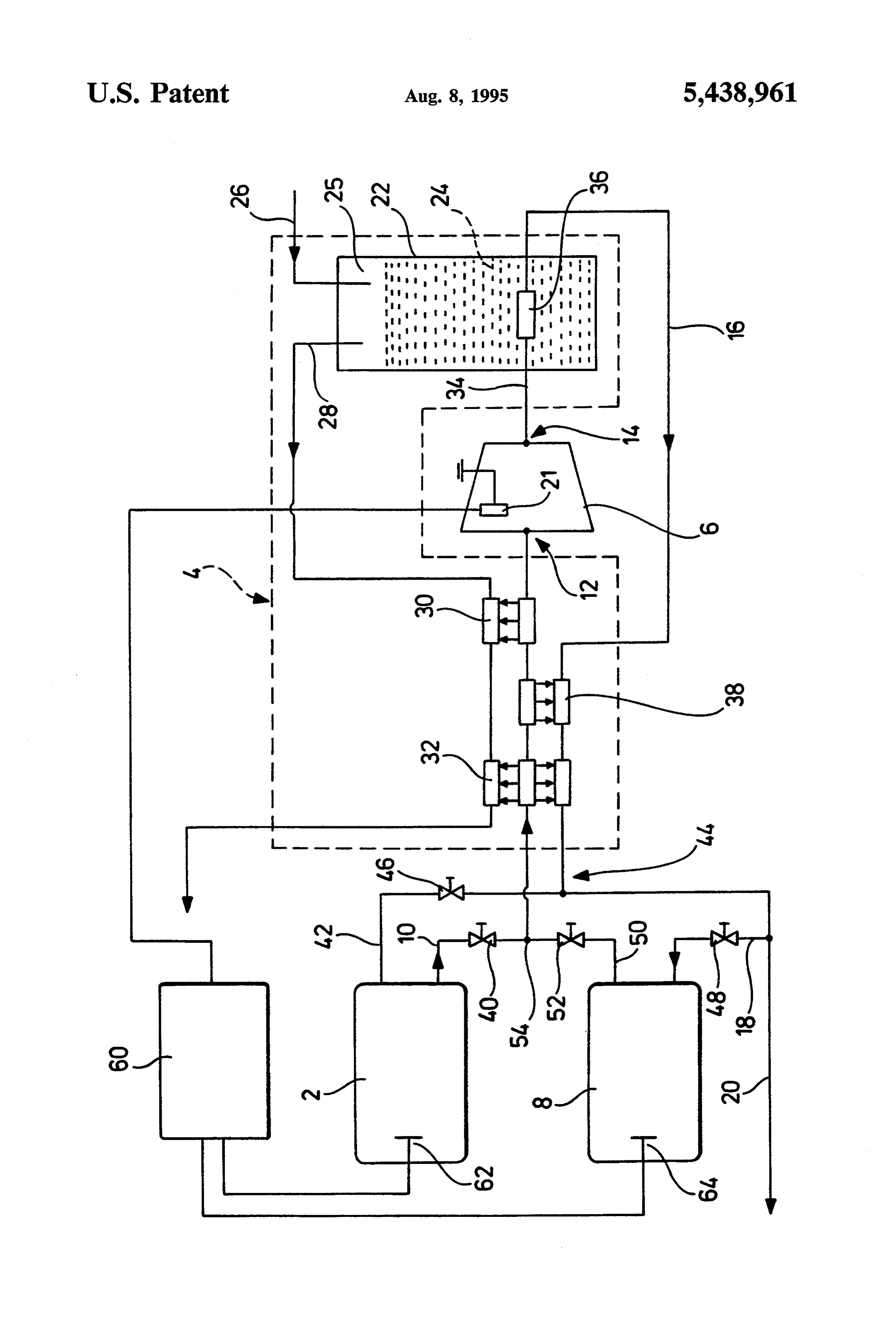
BRIEF DESCRIPTION OF THE DRAWING
mately ambient temperature.
To control the removal from the first pressure-gas
FIG. 1 shows: a schematic illustration of part of a storage means, the first line 10 has a check valve 40. A preferred embodiment of the inventive motor-vehicle third line 42 leads from the first pressure-gas storage drive with two pressure-gas storage means, a cooling means to a section 44 of the second line 16 on the warm device and a cold compressor. side. Provided the pressure in the first pressure-gas The embodiment of the inventive motor-vehicle storage means is above the operational pressure level drive illustrated in the drawing comprises, in detail, a 25 required for the high-pressure injection, hydrogen can first storage means 2 for pressure gas, a cooling device be withdrawn from the first pressure-gas storage means 4, a compressor 6 operating at cryogenic temperatures 2 via this third line 42, via the section 44 on the warm and a second storage means 8 for pressure gas. side as well as via the second section 20 of the second A first line 10 leads from the first pressure-gas storage line 16 branching off to the engine and supplied to the means 2 to a low-pressure side 12 of the compressor 6 30 motor-vehicle engine for the combustion. and hydrogen gas to be compressed is taken from the As soon as the pressure in the first pressure-gas stor first pressure-gas storage means 2 and supplied to the age means 2 falls below the operational pressure level, a compressor 6 via this line. A second line 16 leads away stop valve 46 arranged in the third line 42 is closed and from the high-pressure side 14 of the compressor 6 and once the check valve 40 arranged in the first line 10 is then branches into a line section 18 leading to the sec 35 opened hydrogen gas is withdrawn via the first line 10 ond pressure-gas storage means 8 as well as into a sec and compressed to the operational pressure level in the ond line section 20 leading to the motor-vehicle engine inventive manner. Provided, however, hydrogen gas at which is not illustrated. The compressor 6 is driven by a pressure above the operational pressure level is stored an electric drive 21. in the second pressure-gas storage means 8, hydrogen The cooling device 4 comprises a vessel 22 for receiv gas can be withdrawn from this second pressure-gas ing a cryogenic medium 24, in the illustrated case liquid storage means 8 once a stop valve 48 arranged in the nitrogen. A filling line 26 opens into an upper region 25 first section 18 of the second line 16 is opened and sup of the vessel 22 and liquid nitrogen can be supplied to plied via the second line section 20 to the motor-vehicle the vessel 22 via this line; a vapor line 28 also leads away engine for the combustion.
from the upper region 25 of the vessel 22 for carrying 45 Finally, a connecting line 50 with a stop valve 52 is off the liquid nitrogen vaporizing out of the vessel 22. provided between a section 54 of the first line 10 on the Counterflow heat exchangers 30 and 32 are successively warm side and the second pressure-gas storage means 8. arranged in the vapor line 28 and the first line 10 con If, for example, during the filling up of the first pres veying the hydrogen gas to be cooled. During opera sure-gas storage means 2 the check valve 40 and the tion of the motor-vehicle drive, heat is withdrawn from 50 stop valve 52 are opened, the second pressure-gas stor the hydrogen gas to be compressed via these counter age means 8 is filled at the same time with hydrogen gas flow heat exchangers 30 and 32 due to the vaporized at the storage pressure of the gas pump. cryogenic nitrogen. In this respect, the hydrogen gas is The two pressure-gas storage means 2 and 8 are illus cooled to approximately 80 Kelvin and the vaporized trated in the drawing as being of the same size which is, nitrogen heated to ambient temperature. 55 however, not in any way intended to imply the neces A section 34 of the second line 16 leading away from sity of the two pressure-gas storage means having the the high-pressure side 14 of the cold compressor 6 is same dimensions. The second pressure-gas storage kept at the boiling temperature of the liquid nitrogen by means 8 can, in particular, have a smaller volume than means of a thermal coupling 36 which is in direct the first pressure-gas storage means 2.
contact with the liquid nitrogen bath. The high-pressure 60 Furthermore, a control 60 having a pressure sensor side 14 of the compressor 6 is cooled, in particular, via 62 and 64 in each of the pressure-gas storage means 2 this section 34 which is of significance for drawing off and 8, respectively, is provided. If the pressure in one of the compression heat released during compression. the pressure-gas storage means 2 or 8 falls below the A counterflow heat exchanger 38 is provided in the operational pressure level required for the high-pres second line 16 and in the first line 10 between the coun 65 sure injection, the compressor 6 is automatically started terflow heat exchangers 30 and 32; and the counterflow by the control 60 and the valves brought into the corre heat exchanger 32 which also interacts with the first line sponding positions. Similarly, the control switches the 10 is provided behind the heat exchanger 38 in the di compressor off automatically when the pressure in the
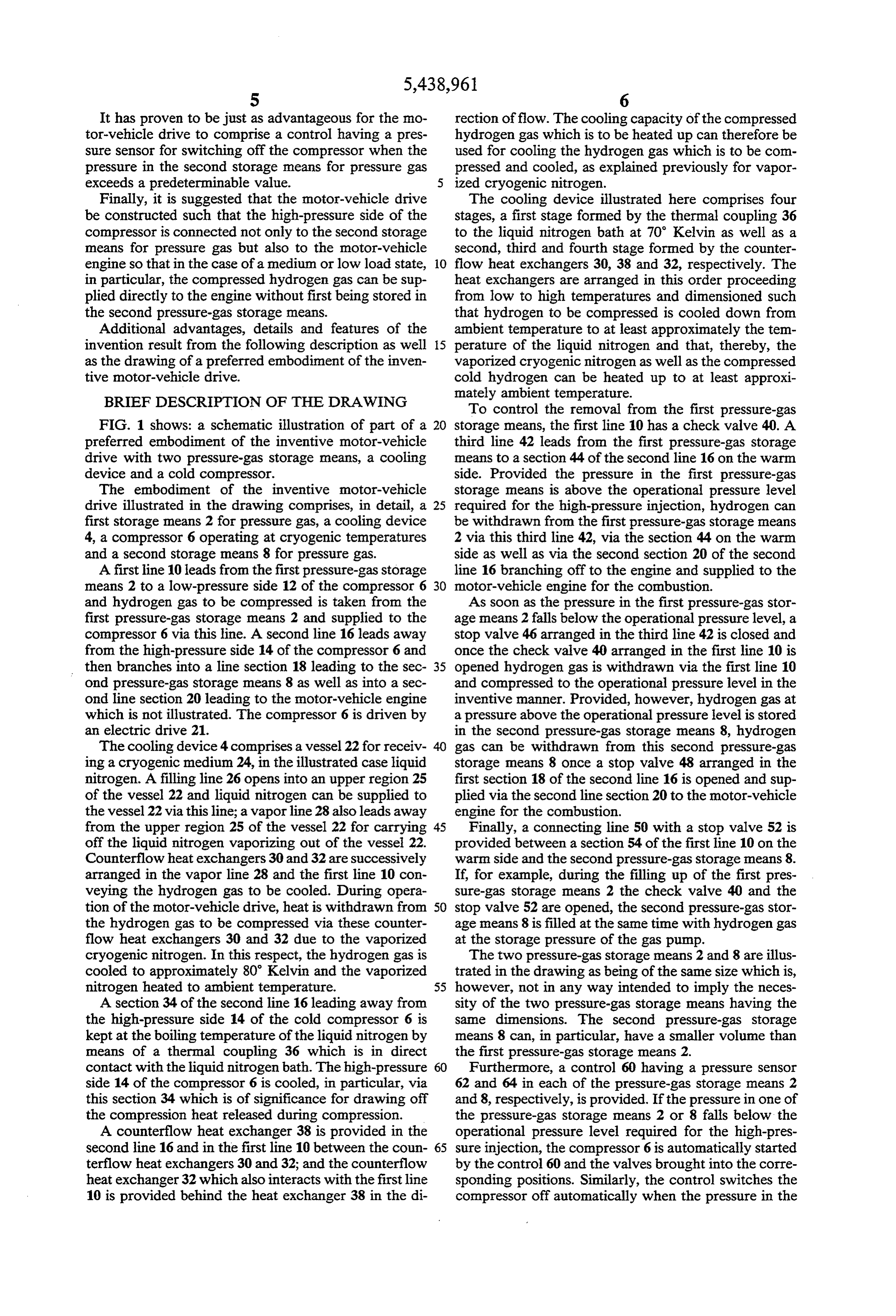
Page 6
second pressure-gas storage means 8 exceeds a predeter a hydrogen injector for injecting hydrogen gas into minable value. said hydrogen engine at said operational pressure. What is claimed is: 11. The motor-vehicle drive of claim 10, further com 1. A method for operating a motor-vehicle engine prising a second storage means for storing hydrogen gas adapted to be driven by hydrogen gas comprising the 5 at said operational pressure, said second storage means steps of: being connected to a high-pressure side of said con storing hydrogen gas at a storage pressure and a stor pressor.
age temperature in a storage means; 12. The motor-vehicle drive of claim 10, wherein said cooling device is adapted to be operated with a cryo transferring the hydrogen gas from the storage means 10 genic to a cooling device; medium.
13. The motor-vehicle drive of claim 10, wherein said cooling the hydrogen gas with the cooling device to cooling device is of a multiple-stage design. a cryogenic temperature below the storage temper 14. The motor-vehicle drive of claim 11, wherein said ature; high-pressure side of said compressor is adapted to be compressing the cooled hydrogen gas to an opera- 15 cooled by said cooling device.
tional pressure above the storage pressure in a com 15. The motor-vehicle drive of claim 11, wherein a pressor operating at a cryogenic temperature; and heat exchanger for heating hydrogen gas compressed to injecting the compressed hydrogen gas at said opera said operational pressure is provided between said high tional pressure into the motor-vehicle engine. pressure side of said compressor and said second storage 2. The method of claim 1 comprising the further step 20 eaS.
of heating the hydrogen gas after said compressing step. 16. The motor-vehicle drive of claim 15, wherein said 3. The method of claim 1, wherein the hydrogen gas heat exchanger is adapted for throughflow of hydrogen is cooled by a cryogenic medium. gas to be cooled.
4. The method of claim 2, wherein the hydrogen gas 25 17. The motor-vehicle drive of claim 12, wherein said cooling device is connected to said hydrogen engine for is cooled and heated by a counterflow heat exchanger supplying system. vaporized cryogenic medium to a combus 5. The method of claim 1, wherein the compressing of tion chamber of said hydrogen engine. the hydrogen gas is essentially carried out isothermally. compressor is adapted todrive 18. The motor-vehicle of claim 10, wherein said be driven by said hydrogen 6. The method of claim 1, wherein the compressor is 30 engine.
driven by the motor-vehicle engine. 19. The motor-vehicle drive of claim 10, wherein said 7. The method of claim 6, wherein the compressor is compressor has an electric drive adapted to be con used for regenerative braking of the motor-vehicle in nected to an electrical system of the motor vehicle. that it is driven by a transmission of the motor vehicle 20. The motor-vehicle drive of claim 10, wherein said during braking. 35 compressor has an electric drive adapted for connection 8. The method of claim 3, wherein vaporized cryo to an electric power supply separate from the motor genic medium is supplied to a combustion chamber of vehicle.
the motor-vehicle engine. 21. The motor-vehicle drive of claim 11, further com 9. The method of claim 8, wherein oxygen is used as prising a control having a pressure sensor for automati the cryogenic medium and supplied to the motor-vehi cally switching on said compressor when the pressure cle engine for combustion in a gaseous state. in at least one of said first and second storage means 10. A motor-vehicle drive comprising: drops below the operational pressure. a hydrogen engine; 22. The motor-vehicle drive of claim 11, further com a first storage means for storing hydrogen gas at a 45 prising cally a control having a pressure sensor for automati switching off said compressor when the pressure storage pressure and a storage temperature; in said second storage means exceeds a predeterminable a cooling device for receiving hydrogen gas trans value.
ferred from said first storage means, and cooling 23. The motor-vehicle drive of claim 11, wherein said transferred hydrogen gas to a cryogenic tempera compressor has a high pressure side connected to said ture below the storage temperature; 50 motor-vehicle engine.
a compressor for compressing the cooled hydrogen 24. A hydrogen-operated motor-vehicle comprising a gas at cryogenic temperatures to an operational motor-vehicle drive as defined in claim 10. pressure above the storage pressure; and ck k x: k k
Provenance
- Collection
- Cited prior art
- Original PDF
- patentimages.storage.googleapis.com →
- Filed
- 1993-12-14
- Pages
- 6
- Method
- pdftotext (the PDF's own text layer) + pdftoppm 300dpi page scans
- Source
- Google Patents bibliographic record
- Granted
- 1995-08-08
- Inventors
- Walter Peschka; Gottfried Schneider; Deutsches Zentrum fuer Luft und Raumfahrt eV
- Transcribed from
- patentimages.storage.googleapis.com →