patent · US5404712
Laser initiated non-linear fuel droplet ignition
11 April 1995
Page 1 — bibliographic record
United States Patent (19) 11 Patent Number: 5,404,712 Few et al. 45 Date of Patent: Apr. 11, 1995 54) LASER INITIATED NON-LINEARFUEL Lavid et al., “Photochemical Ignition of Premixed Hy DROPLET GENTION drogen/Oxidizer Mixtures With Excimer Lasers'. Jimmy D. Few; James W. L. Lewis, M. Lavid, “Photochemical Ignition of Gaseous Mix (75) Inventors: both of Tullahoma, Tenn. tures', pp. 97-100 (no date). E. Dabora, "Laser Ignition of Liquid Fuel Drops', pp.
73 Assignee: University of Tennessee Research 119-133. 7th ICOGER, Gottingen, Fed. Rep. of Ger Corporation, Knoxville, Tenn. many, Aug. 20-24, 1979.
21 Appl. No.: 957,613 Lavid et al., “Infrared Multiphoton Ignition of Alco hols', pp. 69-1-69–4. Chemical and Physical Processes 22 Filed: Oct. 6, 1992 in Combustion 1986 (no month provided). 5ll Int. Cl. .............................................. FO2C 7/264 M. Lavid, "Radiative Augmented Combustion', An 52 U.S. C. .................... or 8 as a so duo so 888 & 8 w 48 w 8 60/39,821 nual Technical Report AFOSR-TR Aug. 1984.
58 Field of Search ............. 60/39.06, 39.821, 39.826, M. Lavid et al., "Infrared multiphoton Ignition and 60/39.828; 123/143 B, 143 R; 431/1, 2, 6, 258 Enhancement of Combustion”, Final Report, NSF
(56) References Cited M. Lavid, "Radiation/Catalytic Augmented Combus
3,258,910 7/1966 Seymour .......................... 60/39,821 3,473,879 10/1969 Berberich ......................... 60/39.82 Primary Examiner-Timothy S. Thorpe 3,861,371 1/1975 Gamell .................................... 431/ Attorney, Agent, or Firm-Perman & Green 4,035,131 7/1977 Cerkanowicz ................... 60/39.821 57 ABSTRACT
4,314,530 2/1982 Giacchetti....................... 123/143 R Method and apparatus for igniting an air/fuel spray (26) 4,343,687 8/1982 Ronn .............................. 204/157.41 comprised of fuel droplets. The apparatus includes a 4,416,226 1/1983 Nishida et al. .................. 123/143 B coherent optical source (12) for introducing at least one 4,434,753 3/1984. Mukainakano et al. ........ 123/143 B pulse of coherent radiation into the air/fuel spray. The 4,556,020 12/1985 Hickling .................................. 431/6 4,726,336 2/1988 Hoppie et al. .................. 123A143 B pulse generates free electrons and initiates a develop 4,947,640 8/1990 Few et al. . ment of a plasma within the air/fuel spray. The coher ent source maintains the pulse of coherent radiation and
FOREIGN PATENT DOCUMENTS pumps the developing plasma to higher energies. The 1236561 6/1971 United Kingdom . pulse is terminated at a time after the plasma has 1360196 7/1974 United Kingdom . reached a predetermined energy and before ignition of
OTHER PUBLICATIONS
the air/fuel spray. The non-linear ignition system of the invention employs a gas/vaporinterface region at a fuel
Copy of Notification of Trans. of In’t Search Report droplet surface and an electric field that extends from dated 5 Jan. 1994, for counterpart, foreign filed patent and exists outside of a fuel droplet. Free electrons are application No. PCT/US93/09633. accelerated to higher energies by the electric field sur Brad E. Forch et al., Technical Report BRL rounding the fuel droplet. The accelerated electrons TR-27409, U.S. Army Ballistic Research Laboratory, initiate a breakdown near adjacent fuel droplets and the entitled “Photochemical Ignition Studies II . . . 'Jun. liberation of further free electrons. In a short period of 1986. time an avalanche process occurs that creates a high Andrezik W. Miziolek et al. Technical Report BRL density of free electrons and ions which results in the TR-2644, U.S. Army Ballistic Research Laboratory, formation of a plasma. “Photochemical Ignition Studies. I. Laser Ignition of
Flowing Premixed Gases', Feb., 1985. 6 Claims, 1 Drawing Sheet
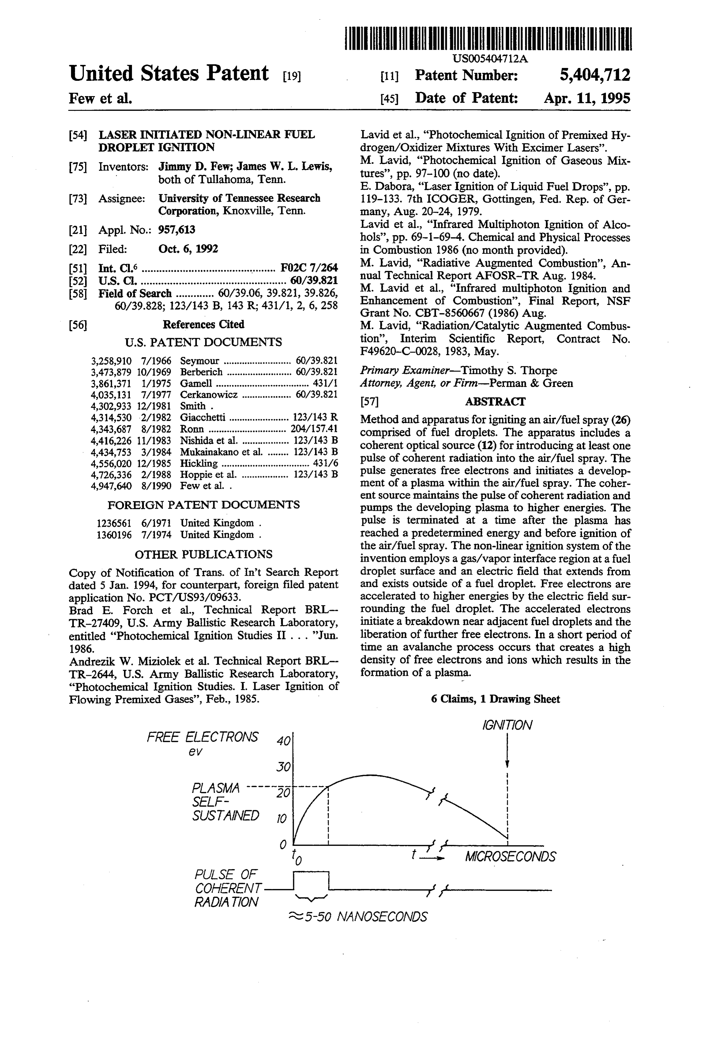
IGNITION
FREE ELECTRONS
SUSTAINED to
--- MCROSECONDS
PULSE OF
RADATION N-N-1 -- - ast 5-50 NANOSECONDS
Page 2
Drawing sheet — no readable text.
Page 3
Report BRL-TR-2644, U.S. Army Ballistic Research
LASER NITATED NON-LNEAR FUEL Laboratory, "Photochemical Ignition Studies. I. Laser DROPLET IGNITION Ignition of Flowing Premixed Gases', February 1985.
FIELD OF THE INVENTION
1981, entitled "Jet Engine Augmentor Operation at
This invention relates generally to ignition systems High Altitudes” by Marvin M. Smith there is disclosed and, in particular, to the ignition of fuel droplets by a a pulsed CO2 TEA laser that is employed to generate laser initiated process. laser-supported absorption (LSA) waves within a jet engine augmentor. The LSA waves are initiated by a
BACKGROUND OF THE INVENTION 10 laser beam reflecting off of targets, such as fuel droplets, The laser ignition of fuel droplets, such as those found in the eye of a cyclonic air action in a recirculation zone in the combustion chamber of a gas turbine engine, of the augmentor. This is said to cause the emission of provides several significant advantages over conven electrons which serve as priming electrons to break tional spark plug type ignitors. For example, with a down air into a plasma of high temperature (10,000 to laser ignitor the combustion process can be started in a 15 20,000 K). The LSA waves are said to be initiated by more optimum chamber position. Spark ignitors are directing a 10.6 micron wavelength converging beam typically positioned at a peripheral, non-optimal posi having a minimum intensity of 6x10⁸W/cm2. The air tion of a combustion chamber, while the fuel spray to be breakdown is said to proceed via inverse bremsstrah ignited is located in a central portion adjacent to a fuel lung heating. It is stated that a hot airplasma of 1-2 ev injector. Also, a laser ignition system that operates out 20 is formed which propagates back up the laser beam side the combustion chamber, with an appropriate opti away from the formed plasma where most of the laser cal coupling into the fuel spray, is not subject to the beam energy is absorbed. The system of Smith is said to type of degradation experienced by internally mounted measure the ambient air pressure and to vary the pulse spark ignitors. This degradation of spark ignitors is repetition rate of the laser such that the fuel-air ratio in known to cause eventual failure after prolonged use. 25 the wave combustion is continuously maintained at a In U.S. Pat. No. 4,947,640, issued Aug. 14, 1990, high thermal efficiency. Smith also makes reference to entitled "Gas Turbine Engine Photon Ignition System', the two of the present inventors describe method and appa withuse of "additives” that may be used in conjunction the fuel.
ratus for igniting a hydrocarbon fuel that is comprised of droplets of hydrocarbon fuel. The hydrocarbon fuel 30 ofThe teaching of Smith does not address the problem is provided as an air/fuel spray. Electromagnetic radia forlow use powered and light-weight laser ignition systems within a gas turbine engine combustor. As is tion having wavelengths primarily within a range of approximately 185 nm to approximately 400 nm (UV) evident from his disclosure, Smith envisions a high generated and directed into the air/fuel spray. The powered laser source to generate LSA waves within droplets absorb the energy, are heated, fragmented and 35 the engine augmentor.
ignited. The use of electromagnetic radiation within the However, one important criteria for an aircraft laser ultraviolet region is shown to be beneficial because of a ignition system is that the system be a low powered high absorption of radiation within this wavelength system having a small physical size and weight. It is thus range by hydrocarbon fuels such as JP-4 and JP-5. one object of this invention to provide for a laser initi The following U.S. and foreign patents are cited as 40 ated ignition of a fuel spray within a combustion cham relating to the ignition of and/or the preconditioning of ber with a low powered laser source. fuels with electromagnetic energy: It is a further object of this invention to provide for a U.S. Pat. No. 4,035,131, issued Jul. 12, 1977, entitled laser initiated non-linear ignition process of a fuel spray “Control of the Initiation of Combustion and Control of within a combustion chamber of a gas turbine engine. Combustion' by A. E. Cerkanowicz; U.S. Pat. No. 45 SUMMARY OF THE INVENTION 4,726,336, issued Feb. 23, 1988, entitled “UV Irradiation
Apparatus and Method for Fuel Pretreatment Enabling The foregoing and other problems are overcome and Hypergolic Combustion' by L. O. Hoppie et al.; U.S. the objects of the invention are realized by method and Pat. No. 3,258,910, issued Jun. 8, 1962, entitled “Fiber apparatus for igniting an air/fuel spray comprised of Optics Ignition” by R. J. Seymour; U.S. Pat. No. 50 fuel droplets. The apparatus includes a laser optical 3,473,879, issued Oct. 21, 1969, entitled "Shock Wave Source for introducing at least one pulse of coherent Burner' by B. Berberich; U.S. Pat. No. 3,861,371, is optical radiation into the air/fuel spray. The radiation sued Jan. 21, 1975 entitled "Ignition System for Engine' Source provides a light pulse that generates free elec to J. Gamell; U.S. Pat. No. 4,416,226, issued Nov. 22, trons and initiates a development of a plasma within the 1983, entitled “Laser Ignition Apparatus for an Internal 55 air/fuel spray. The source maintains the pulse of laser Combustion Engine' by M. Nishida et al.; U.S. Pat. No. radiation and pumps the developing plasma to higher 4,434,753, issued Mar. 6, 1984, entitled "Ignition Appa energies. The pulse is terminated at a time after the ratus for Internal Combustion Engine' to Mukainakano plasma has reached a predetermined energy and before et al.; and two U.K. Patents to D. Brown, both entitled ignition of the air/fuel spray.
"Ignition Systems', specifically: 1,236,561, published 60 In accordance with the invention, the pulse width of Jun. 23, 1971, and 1,360,196 published, Jul. 17, 1974. the incident laser beam may be made relatively short as The following two technical reports are cited for compared to the amount of time to achieve ignition, teaching the ignition of premixed flowing gases with thereby achieving low powered operation. The process electromagnetic energy: Brad E. Forchet al., Technical of plasma generation occurs within several tens of nano Report BRL-TR-27409, U.S. Army Ballistic Research 65 seconds after the laser pulse is introduced into a com Laboratory, entitled “Photochemical Ignition Studies. bustion chamber, such as a combustion chamber associ II Oxygen-Atom Two-Photon Resonance Effects', ated with a gas turbine engine. The actual, global igni June, 1986; and Andrezik W. Miziolek et al. Technical tion of the air/fuel spray may not occur for up to some
Page 4
number of microseconds after the pulse is first applied. coupled to a radiation delivery means, such as, for ex However, the pulse width of the laser source can be ample, an optical fiber 16 which delivers the laser radia made significantly shorter than the amount of time that tion to a focussing element 18. The focussing element 18 elapses between plasma development and the ignition of provides a focussed beam 20 of laser radiation. The the air/fuel spray. That is, the pulse of coherent, laser 5 focussed beam 20 is directed to within a combustion radiation is introduced and removed within a period of chamber 22. The combustion chamber 22 is preferably time that is less than a time required to achieve ignition. the combustion chamber of a gas turbine engine, al In accordance with the teaching of the invention, the though other combustion chamber embodiments also pulse of coherent radiation initiates the development of benefit from the teaching of the invention. A fuel injec the plasma, and then pumps the plasma to an energy at 10 tor 24 is provided for introducing an air/fuel spray 26 which the plasma becomes self-sustaining. This advan into the combustion chamber 22. The air/fuel spray 26 tageously provides for a relatively low powered opera includes fuel droplets having a diameter within a range, tion as compared to the prior art. typically, of 20 micrometers to 1000 micrometers or The non-linear ignition system of the invention em greater. The mean diameter of fuel droplets within the ploys a gas/vapor interface region at the fuel droplet 15 air/fuel spray 26 is a function of several parameters, surface and an electric field that extends from and exists including fuel temperature and the design of the injec outside of a fuel droplet. The shape and extent of the tor 24. The focussed beam 20 is positioned such that the electric field is a function of the index of refraction of focal point 20a is located within the fuel spray 26. Posi the droplet at the laser wavelength, the droplet size, the tioning the focal point 20a within the fuel spray 26 droplet composition, and other factors. Free electrons 20 increases the probability that one or more fuel droplets are accelerated to higher energies by the electric field will be at the focal point 20a.
surrounding the fuel droplet. These accelerated elec In FIG. 1 the focussing element 18 may be a lens, or trons initiate a breakdown near adjacent droplets and may be embodied in a self-focussing type of optical the liberation of additional free electrons. In a short fiber. Also, it is within the scope of the invention to period of time an avalanche process occurs that creates 25 provide a plurality of fiber optic conductors 18 for a high density of free electrons and ions which form a providing a plurality of focussed beams 20 within the plasma. fuel spray 26, thereby increasing the probability that the In accordance with a method of igniting an air/fuel non-linear ignition process will be initiated. spray comprised of fuel droplets there are disclosed the Also, it is within the scope of the invention to provide steps of (a) providing the air/fuel spray within a com 30 a feedback mechanism for varying a pulse rate and/or a bustion chamber; (b) introducing at least one pulse of pulse width of the laser 12. In FIG. 1 this feedback coherent radiation into the air/fuel spray, the at least mechanism includes a silicon photodiode 28 that is re one pulse interacting with free electrons and initiating a sponsive to wavelengths associated with the flame development of a plasma within the air/fuel spray; (c) within the combustion chamber 22. The silicon photodi maintaining the at least one pulse of coherent radiation 35 ode 22 generates a signal indicating that ignition has for pumping the developing plasma; and (d) terminating been achieved, the signal being fed back to the pulse the at least one pulse of coherent radiation at a time controller 14 for disabling the pulsing of the laser 12. after the plasma has reached a predetermined energy This feedback mechanism may also be employed to and before ignition of the air/fuel spray. advantage if the flame within the combustion chamber BRIEF DESCRIPTION OF THE DRAWING 22 is lost, so as to reinitiate the ignition process by en abling the laser 12 to generate pulses. Manual control of
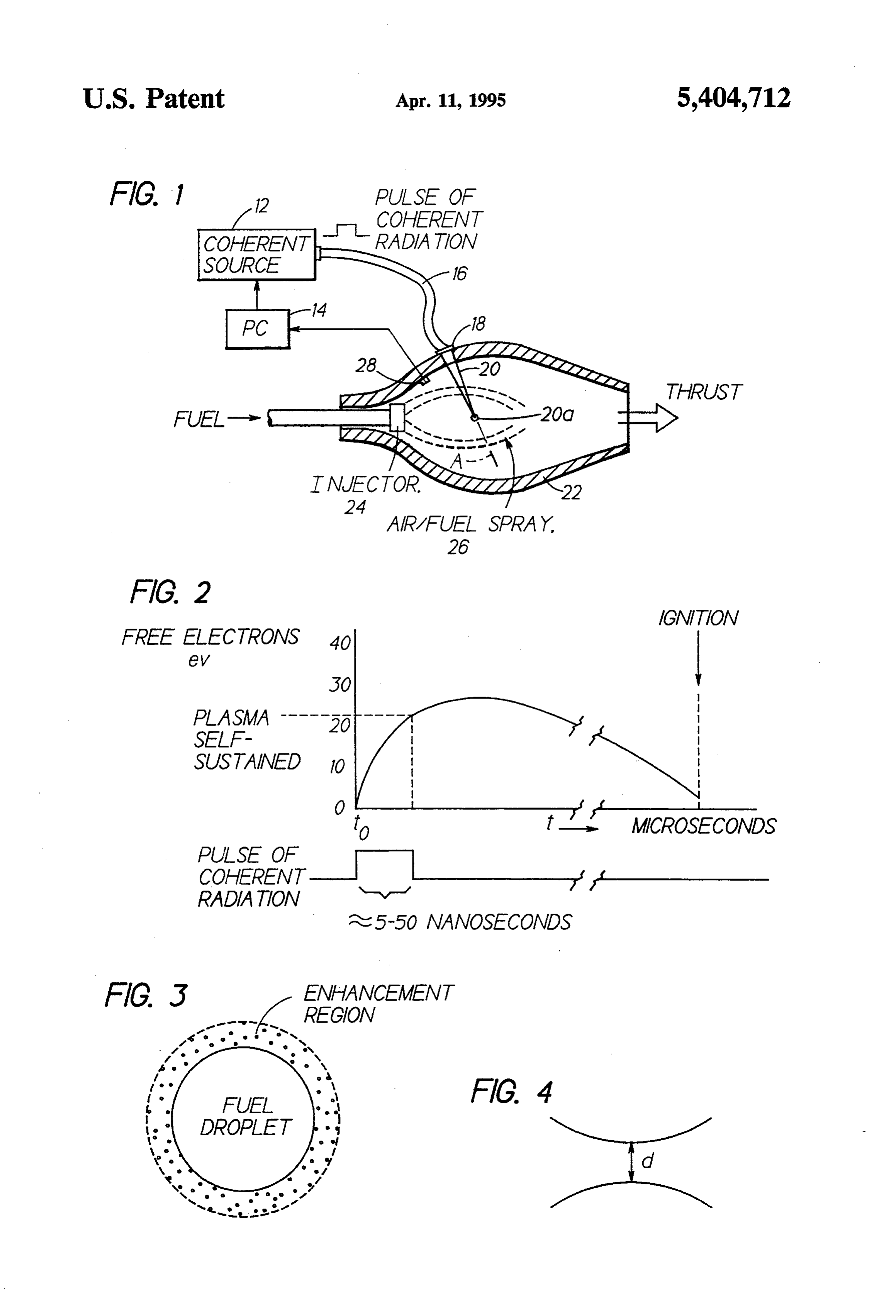
The above set forth and other features of the inven the laser 12 operation is generally always provided. tion are made more apparent in the ensuing Detailed In accordance with the invention the ignition of the Description of the Invention when read in conjunction air/fuel spray 26 proceeds by a non-linear process, as with the attached Drawing, wherein: 45 opposed to a linear process. In a linear process, the fuel FIG. 1 is a block diagram showing the laser ignition droplets absorb the electromagnetic radiation and are system of the invention coupled to a combustion cham heated thereby to an ignition temperature. Although ber of a gas turbine engine for igniting a fuel spray providing ignition, the linear system typically requires therein; significantly more input power than the non-linear pro FIG. 2 is a graph showing, as a function of time, the 50 cess described herein.
energy of free electrons of a plasma that is laser-initiated In contradistinction to the linear system, the non-lin within a combustion chamber; ear ignition system of the invention relies upon a gas/- FIG. 3 is an enlarged view, not to scale, of a fuel vapor interface region at the droplet surface and upon droplet and the enhancement region surrounding the an electric field that extends from and exists outside of droplet; and 55 a fuel droplet. This electric field is generated by the FIG. 4 is an illustration of a focal region of a laser interaction of the droplet and the laser energy contained beam. within the pulsed beam 20. The shape and extent of this DETAILED DESCRIPTION OF THE electric field is a function of the index of refraction of INVENTION the droplet at the laser wavelength, the droplet size, the droplet composition, and other factors.
Referring to FIG. 1 there is shown a laser ignition Referring to FIG. 2 it can be seen that a pulse of system constructed and operated in accordance with coherent radiation having a predetermined pulse width the invention. The system includes a coherent source or and power density is introduced into the combustion laser 12 having a pulse controller (PC) 14 coupled chamber 22 at time (to). The focussed pulse initiates a thereto. It should be understood that the coherent 65 breakdown process, including the formation of a shock source 12 may include, if desired, frequency doubling or wave. Initially, typically but a few free electrons are tripling apparatus, Q-switching apparatus, and/or other generated from the gas/vapor surrounding a fuel drop optical devices. An output of the laser 12 is optically let. These free electrons are then accelerated to higher
Page 5
energies by the aforementioned electric field surround is initially approximately one electron volt. However, ing the fuel droplet. These accelerated electrons initiate after the plasma is developed energies of approximately a breakdown in the gas/vapor surrounding adjacent 30 electron volts may be achieved. In this regard it is droplets and the liberation of further free electrons. noted that energies of approximately 10 electron volts Initially, free electron movement is approximately col are required to disassociate a molecule, while 15 elec linear with the axis (A) of the focussed beam 20. How tron ever, as the plasma builds the electron movement di it canvolts is sufficient to ionize oxygen molecules. Thus, verges from the axis (A) of the beam 20 and rapidly that required tobeionize readily seen that energies significantly above the oxygen molecules are present spreads throughout the air/fuel spray26. The free elec within the plasma of the combustion chamber. trons are accelerated to higher energies, forming “hot” O electrons, which extend over a large area of the com As can be seen in FIG. 2, the pulse width of the inci bustion chamber 22. The plasma of free electrons and dent laser beam 20 is relatively short compared to the ions that is generated within the combustion chamber amount of time to achieve ignition. That is, the process 22 may have a temperature approaching 20,000 K. of plasma generation occurs within several tens of nano As employed herein, a plasma is considered to be a 15 Seconds after the laser pulse is introduced into the com gaseous region containing free electrons and ions at a bustion chamber 22. However, the actual, global igni given density or concentration. Typical electron/ion tion of the fuel spray 26 may not occur for up to some densities associated with plasmas are in the range of 108 number of microseconds. As a result, the pulse width of cm3 to 1010 cm3. It has been found that the use of the the laser radiation can be made significantly shorter invention results in a plasma having significantly higher 20 than the amount of time that elapses between plasma densities in the range of 1016 cm-3 to 1018 cm3. The development and the ignition of the air/fuel spray 26. pulse of laser energy is maintained for pumping the That is, the pulse of coherent radiation is introduced developing plasma to at least a point whereat the plasma becomes self-sustaining; that is, to a point where the into ment, the combustion chamber to initiate plasma develop maintained at least until the plasma becomes self plasma will exist for a period of time without requiring 25 sustained, input energy from the laser beam. As employed herein, that is less and then removed, all within a period of time the point at which the plasma becomes self-sustained is advantageouslyaprovides than time required to achieve ignition. This for a low powered operation, considered to be at free electron energies in the range of relative to the linear systems of the prior art, and to the approximately 20 electron volts (ev) to approximately 30 ev. 30 high powered system described by Smith in the above The plasma generation is believed to operate by a mentioned U.S. Pat. No. 4,302,933. As was noted above, multi-photon process wherein bound electrons absorb Smith generates a LSA wave, that is, a propagating several photons, each photon of lesser energy than an thermal wave. The laser of Smith is thus required to ionization energy. For example, a laser beam of approxi maintain the plasma so as to provide the thermal wave. mately one micrometer wavelength initially generates 35 More specifically, the generation of an LSA-wave is free electrons having energies of approximately one consistent with a longer pulsewidth (microsecond) laser electron volt. Absorption of several such low energy Source. In contradistinction, the pulsewidth taught by photons by an electron bound to an oxygen atom, this invention, which is on the order of nanoseconds, is within a relatively short period of time, results in the sufficiently short such that the formation of an absorp electron absorbing sufficient energy to cause the atom tion wave is unlikely. That is, the formation time of such to become ionized. The resulting ionized oxygen atom a wave is believed to be much greater than the pulse thus contributes a free electron to the plasma. width of the source 12. This invention requires only that The actual ignition of the air/fuel spray is believed to the free electrons absorb the laser energy. It is further proceed primarily by a diffusion and recombination believed that the subsequent electron motion is not process. The fully developed, self-sustaining plasma 45 solely toward the laser source, as is indicated in U.S. contains free electrons and ions. As the plasma begins to Pat. No. 4,302,933.
cool, free electrons are captured by ions to create neu The ignition process utilizes the presence of free elec tral, excited atoms. These neutral, excited atoms in turn trons. These electrons may be naturally present, or may create neutral, excited molecules/atoms which are the precursors to ignition. The recombination process that 50 be
the result of photoionization processes from gaseous vapor species of the fuel droplet itself. As seen in results in ignition may require several microseconds, as FIG. 3, the droplet provides a region near the surface indicated by FIG. 2. At the time of ignition, the remain for which there is an enhancement of the electric field ing free electrons are believed to have energies on the produced by the laser source/fuel droplet interaction. order of approximately one to approximately five elec This enhancement region has an approximate thickness
Initially, it has been found that the fuel spray 26 ap of 1 wavelength. Significantly, there is no requirement pears substantially transparent to the laser beam 20, and for an eye of a cyclonic air action as stated in U.S. Pat. relatively little absorption of the beam 20 occurs. How No. 4,302,933.
ever, as the plasma builds within the combustion cham As has been previously described, the teaching of this ber 22 the absorption of the laser pulse 20 has been 60 invention is directed towards providing a low powered found to increase until, finally, the energy of the laser ignition system. This aspect of the invention is made pulse 20 is almost totally absorbed by the plasma. Laser apparent by a comparison with the system described in energy absorptions of 90-95% are typical for the fully U.S. Pat. No. 4,302,933. A minimum converging beam developed plasma. This increased absorption further intensity that is disclosed in 4,302,933 is 6X 10⁸ W/cm2 heats the plasma and "pumps” the plasma energy to 65 (utilizing a 10.6 micron wavelength). higher levels. FIG. 4 illustrates a focal region of a laser, where d is As was stated, for a laser with an approximately one a minimum diameter of a focal volume. A minimum micrometer wavelength the energy of the free electrons intensity Imin is given by
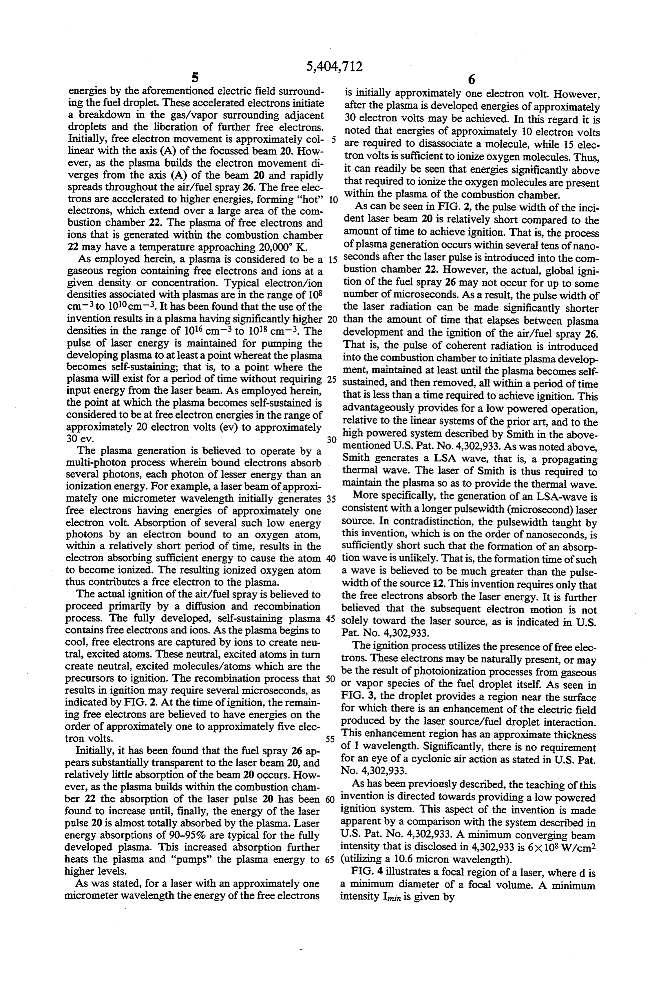
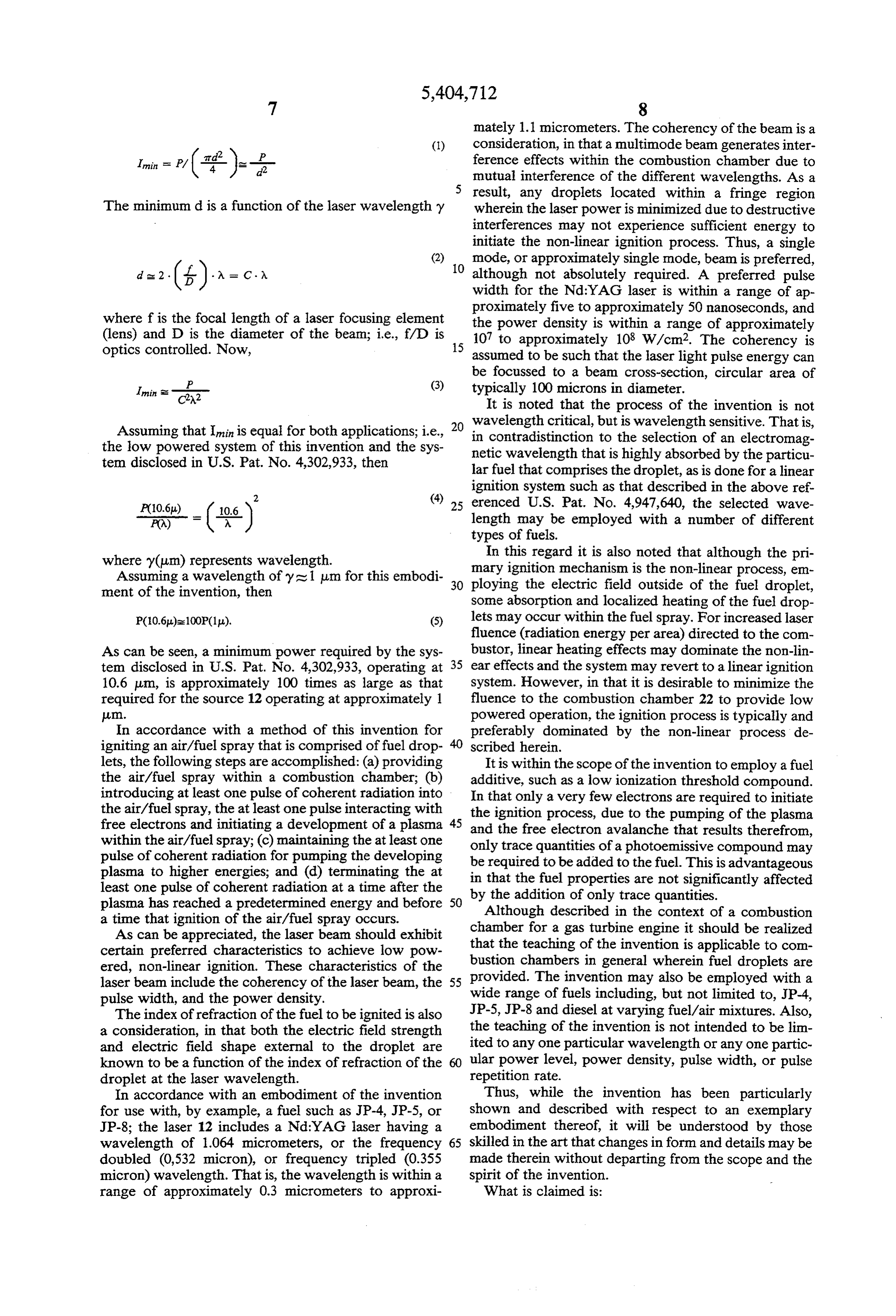
Page 6
mately 1.1 micrometers. The coherency of the beam is a
(1) consideration, in that a multimode beam generates inter ference effects within the combustion chamber due to
Imin = P/ (#)--i- mutual interference of the different wavelengths. As a result, any droplets located within a fringe region
The minimum d is a function of the laser wavelength y wherein the laser power is minimized due to destructive interferences may not experience sufficient energy to initiate the non-linear ignition process. Thus, a single (2) mode, or approximately single mode, beam is preferred, d = 2 (f) = c 10 although not absolutely required. A preferred pulse width for the Nd:YAG laser is within a range of ap proximately five to approximately 50 nanoseconds, and where f is the focal length of a laser focusing element the power density is within a range of approximately (lens) and D is the diameter of the beam; i.e., f/D is 15 107 to approximately 108 W/cm2. The coherency is optics controlled. Now, assumed to be such that the laser light pulse energy can be focussed to a beam cross-section, circular area of
P (3) typically 100 microns in diameter.
It is noted that the process of the invention is not wavelength critical, but is wavelength sensitive. That is,
Assuming that Imin is equal for both applications; i.e., 20 in the low powered system of this invention and the sys netic contradistinction to the selection of an electromag tem disclosed in U.S. Pat. No. 4,302,933, then wavelength that is highly absorbed by the particu lar fuel that comprises the droplet, as is done for a linear
ignition system such as that described in the above ref
P(10.6) ( 10.6 ) 25 erenced U.S. Pat. No. 4,947,640, the selected wave P(A) length may be employed with a number of different types of fuels.
where y(um) represents wavelength. In this regard it is also noted that although the pri Assuming a wavelength of y's 1 um for this embodi 30 ployingmary ignition mechanism is the non-linear process, em ment of the invention, then the electric field outside of the fuel droplet, some absorption and localized heating of the fuel drop
P(10.6)s 100P(1p). lets may occur within the fuel spray. For increased laser
fluence (radiation energy per area) directed to the com
As can be seen, a minimum power required by the sys bustor, linear heating effects may dominate the non-lin tem disclosed in U.S. Pat. No. 4,302,933, operating at 35 ear effects and the system may revert to a linear ignition 10.6 um, is approximately 100 times as large as that system. However, in that it is desirable to minimize the required for the source 12 operating at approximately 1 fluence to the combustion chamber 22 to provide low l. powered operation, the ignition process is typically and In accordance with a method of this invention for preferably dominated by the non-linear process de igniting an air/fuel spray that is comprised of fuel drop scribed herein.
lets, the following steps are accomplished: (a) providing It is within the scope of the invention to employ a fuel the air/fuel spray within a combustion chamber; (b) additive, such as a low ionization threshold compound. introducing at least one pulse of coherent radiation into In that only a very few electrons are required to initiate the air/fuel spray, the at least one pulse interacting with free electrons and initiating a development of a plasma 45 the ignition process, due to the pumping of the plasma within the air/fuel spray; (c) maintaining the at least one onlythe and free electron avalanche that results therefrom, trace quantities of a photoemissive compound may pulse of coherent radiation for pumping the developing be required to be added to the fuel. This is advantageous plasma to higher energies; and (d) terminating the at in that the fuel properties are not significantly affected least one pulse of coherent radiation at a time after the by plasma has reached a predetermined energy and before 50 the addition of only trace quantities. Although described in the context of a combustion a time that ignition of the air/fuel spray occurs. chamber for a gas turbine engine it should be realized As can be appreciated, the laser beam should exhibit that the teaching of the invention is applicable to com certain preferred characteristics to achieve low pow bustion chambers in general wherein fuel droplets are ered, non-linear ignition. These characteristics of the provided. The invention may also be employed with a laser beam include the coherency of the laser beam, the 55 pulse width, and the power density. wide range of fuels including, but not limited to, JP-4, The index of refraction of the fuel to be ignited is also JP-5, JP-8 and diesel at varying fuel/air mixtures. Also, a consideration, in that both the electric field strength the teaching of the invention is not intended to be lin and electric field shape external to the droplet are ited to any one particular wavelength or any one partic known to be a function of the index of refraction of the ular power level, power density, pulse width, or pulse droplet at the laser wavelength. repetition rate.
In accordance with an embodiment of the invention Thus, while the invention has been particularly for use with, by example, a fuel such as JP-4, JP-5, or shown and described with respect to an exemplary JP-8; the laser 12 includes a Nd:YAG laser having a embodiment thereof, it will be understood by those wavelength of 1.064 micrometers, or the frequency 65 skilled in the art that changes in form and details may be doubled (0,532 micron), or frequency tripled (0.355 made therein without departing from the scope and the micron) wavelength. That is, the wavelength is within a spirit of the invention.
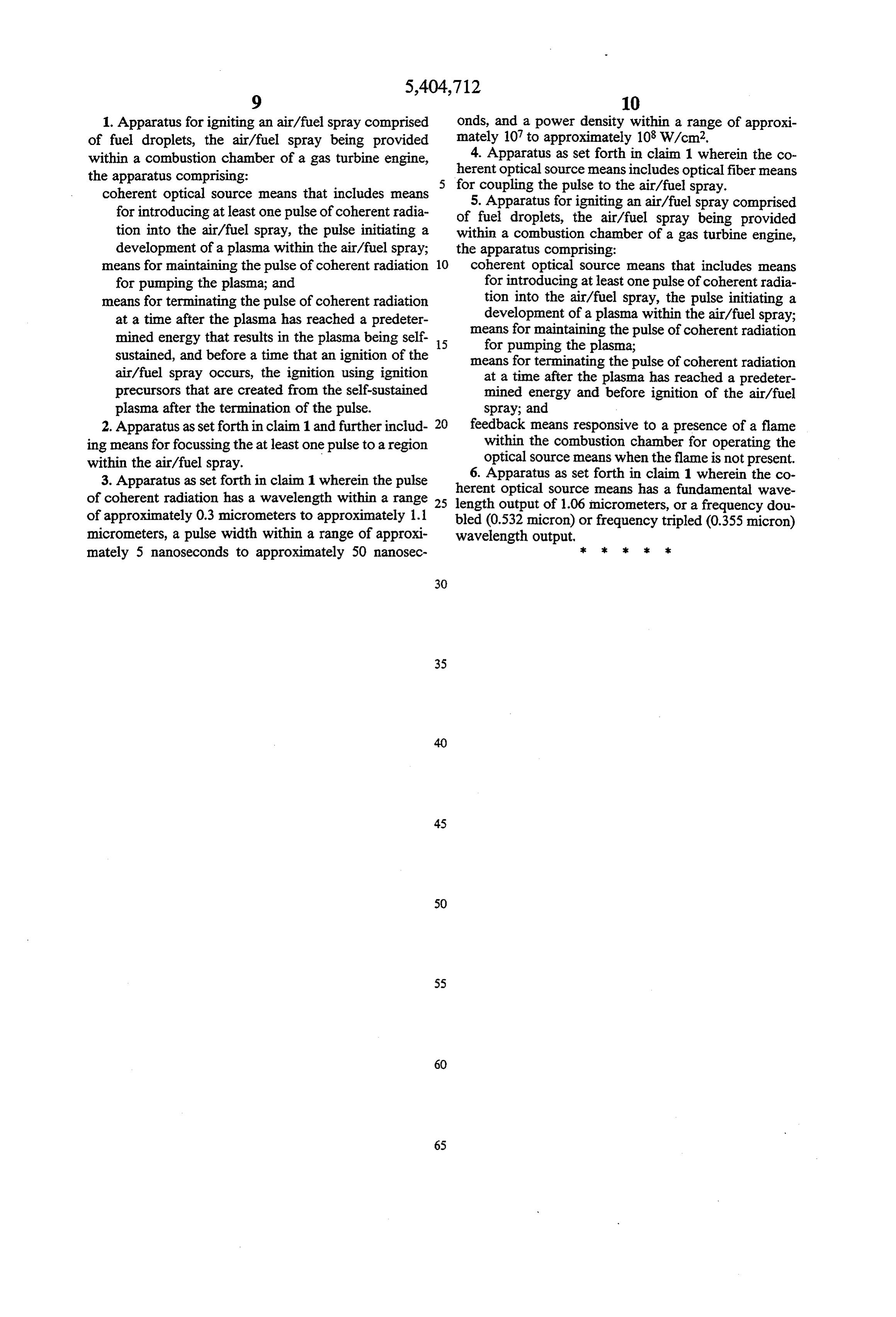
range of approximately 0.3 micrometers to approxi What is claimed is:
Page 7
1. Apparatus for igniting an air/fuel spray comprised Onds, and a power density within a range of approxi of fuel droplets, the air/fuel spray being provided mately 107 to approximately 108 W/cm2. within a combustion chamber of a gas turbine engine, 4. Apparatus as set forth in claim 1 wherein the co the apparatus comprising: herent optical source means includes optical fiber means coherent optical source means that includes means for coupling the pulse to the air/fuel spray. for introducing at least one pulse of coherent radia of fuel droplets,forthe 5. Apparatus igniting an air/fuel spray comprised air/fuel spray being provided tion into the air/fuel spray, the pulse initiating a within a combustion chamber of a gas turbine engine, development of a plasma within the air/fuel spray; the apparatus comprising:
means for maintaining the pulse of coherent radiation 10 coherent optical source means that includes means for pumping the plasma; and for introducing at least one pulse of coherent radia means for terminating the pulse of coherent radiation tion into the air/fuel spray, the pulse initiating a at a time after the plasma has reached a predeter development of a plasma within the air/fuel spray; mined energy that results in the plasma being self 15 means for maintaining the pulse of coherent radiation for pumping the plasma;
sustained, and before a time that an ignition of the means for terminating the pulse of coherent radiation air/fuel spray occurs, the ignition using ignition at a time after the plasma has reached a predeter precursors that are created from the self-sustained mined energy and before ignition of the air/fuel plasma after the termination of the pulse. spray; and 2. Apparatus asset forthin claim 1 and further includ 20 feedback means responsive to a presence of a flame ing means for focussing the at least one pulse to a region within the combustion chamber for operating the within the air/fuel spray. optical source means when the flame is not present. 6. Apparatus as set forth in claim 1 wherein the co 3. Apparatus as set forth in claim 1 wherein the pulse herent optical source means has a fundamental wave of coherent radiation has a wavelength within a range 25 length output of 1.06 micrometers, or a frequency dou of approximately 0.3 micrometers to approximately 1.1 bled (0.532 micron) or frequency tripled (0.355 micron) micrometers, a pulse width within a range of approxi wavelength output, mately 5 nanoseconds to approximately 50 nanosec 3 s
Provenance
- Collection
- Cited prior art
- Original PDF
- patentimages.storage.googleapis.com →
- Filed
- 1992-10-06
- Pages
- 7
- Method
- pdftotext (the PDF's own text layer) + pdftoppm 300dpi page scans
- Source
- Google Patents bibliographic record
- Granted
- 1995-04-11
- Inventors
- Jimmy D. Few; James W. L. Lewis; University of Tennessee Research Foundation
- Transcribed from
- patentimages.storage.googleapis.com →