patent · US4574752
Internal combustion engine shutdown device
11 March 1986
Page 1 — bibliographic record
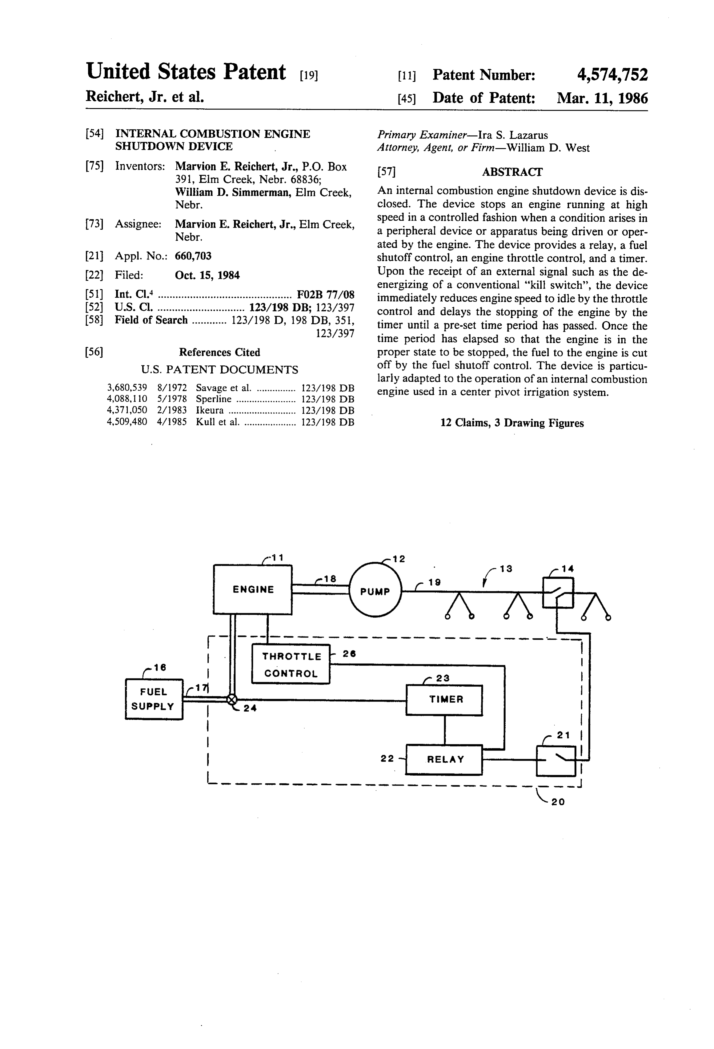
United States Patent (19) 11 Patent Number: 4,574,752 Reichert, Jr. et al. (45) Date of Patent: Mar. 11, 1986 54 INTERNAL COMBUSTION ENGINE Primary Examiner-Ira S. Lazarus SHUTDOWN DEVICE Attorney, Agent, or Firm-William D. West (75) Inventors: Marvion E. Reichert, Jr., P.O. Box 57 ABSTRACT
William D. Simmerman, Elm Creek, An internal combustion engine shutdown device is dis Nebr. closed. The device stops an engine running at high 73) Assignee: Marvion E. Reichert, Jr., Elm Creek, speed in a controlled fashion when a condition arises in Nebr. a peripheral device or apparatus being driven or oper ated by the engine. The device provides a relay, a fuel 21 Appl. No.: 660,703 shutoff control, an engine throttle control, and a timer. 22) Filed: Oct. 15, 1984 Upon the receipt of an external signal such as the de energizing of a conventional "kill switch', the device (51) Int. Cl." .............................................. FO2B 77/08 immediately reduces engine speed to idle by the throttle (52) U.S. Cl. .............................. 123/198 DB; 123/397 control and delays the stopping of the engine by the (58) Field of Search ............ 123/198 D, 198 DB, 351, timer until a pre-set time period has passed. Once the 123/397 time period has elapsed so that the engine is in the 56) References Cited proper state to be stopped, the fuel to the engine is cut
larly adapted to the operation of an internal combustion 3,680,539 8/1972 Savage et al. ............... 123/198 DB engine used in a center pivot irrigation system.
4,509,480 4/1985 Kull et al. .................... 123/198 DB 12 Claims, 3 Drawing Figures
FUE
SUPPLY
Page 2
Drawing sheet — no readable text.
Page 3
time to avoid excessive wear to the engine or other
INTERNAL COMBUSTION ENGINE SHUTDOWN damage to the pump and/or the supply line. The engine DEVICE is abruptly stopped by cutting off the fuel to the engine or by switching off the ignition system by the kill
BACKGROUND OF THE INVENTION 5 switch. Diesel and gasoline engines are normally 1. Field of the Invention stopped by closing off the fuel supply while natural gas The invention relates to an internal combustion en and propane fueled engines are normally stopped by gine shutdown device, and in particular to a device for cutting off the ignition.
a sequential controlled stopping of such an engine used 10 Examples of a number of prior art engine shut-down to power a center pivot irrigation pump. devices can be found in representative patents. Gener 2. Discussion of the Technical Problems ally, the prior art relates to devices adapted to engines Internal combustion engines including diesel and used in motor vehicles which must be shutoff due to a gasoline fueled engines are often used as a source of collision or some other emergency situation particular stationary power in applications where the operation of to motor vehicles. Very few devices relate to stationary the engine is controlled by automatic devices instead of 5 engine applications and none known are directed to by human operators. One such application is in a center providing a controlled timed shutdown in order to re pivot irrigation system in which the engine is used to duce engine wear or system damage in the event of a provide power to run the pump. problem in an external apparatus being powered by the As conditions change which effect the continued safe engine.
operation of such a system, the engine must be stopped 20 until the condition is remedied. A missalignment in a thatU.S. Pat. No. 3,550,717 to Doty discloses a device closes the fuel line in a moving engine in the event center pivot is one example of a condition which would of a collision or theft. The invention brings about an necessitate an engine shutdown. Since the operator is immediate stopping of the engine rather than a reduc not available to stop the engine, the shutdown must be tion to idle speed first.
The ordinary device for automatically stopping an safeU.S. Pat. No. 3,371,667 to MacMillan disclosed a fail throttle control system for a vehicle in which the engine used to provide power to a pump in a center pivot irrigation system is a conventional "kill switch' engine speed is reduced to idle in the event the accelera which is is a switch directly sensitive to misalignment or tor is jammed. The invention provides for continued some other unsafe condition. When the kill switch is 30 operation of the engine at a reduced speed rather than a activated by the unsafe condition, it shuts off the engine timed shutdown.
by shutting off the ignition or stopping the fuel from U.S. Pat. No. 3,888,219 to Rogerson discloses an reaching the engine. The use of such a directly con overspeed protection device for limiting the speed of a nected kill switch to stop an engine is well known in the motor vehicle engine. The invention relates to the art. 35 throttle linkage and is not responsive to an external A kill switch can also be used in an indirect method of condition.
stopping an engine. One example of an indirect method U.S. Pat. No. 4,102,316 to Valbert relates to a hydro is the use of a normally energized kill switch (energized mechanical shutoff for an internal combustion engine. while operating) which is de-energized in the event that The invention is actuated in response to internal condi pump pressure falls below a certain set point. Such an 40 tions of the engine such as low oil pressure or high irrigation system is also fitted with a mechanical dump temperature and is not responsive to external condi valve which opens in the event of a misalignment, tions.
thereby decreasing pump pressure and de-energizing U.S. Pat. No. 4,106,469 to Dey discloses an automatic the kill switch. As in the direct system, once the kill motor kill system in the event the air cleaning system switch is de-energized the engine is immediately 45 becomes clogged. The invention is responsive to the stopped. internal condition of reduced manifold pressure. Many stationary installations of internal combustion U.S. Pat. No. 4,193,385 to Katsumata et al. discloses engines set the operating speed of the engine at a very an engine stopping device for magneto ignition engines high rate in order to achieve the best efficiency and which such as lawnmowers which insures that the en power level. While operating within these high power 50 gine does not restart while it is in the process of stop settings the engines develop high internal temperatures. ping. The invention provides a device for stopping the Unfortunately, the stopping of an engine abruptly at engine by means of the ignition rather than by only such a high power setting can damage the engine and shutting off the fuel.
reduce engine life. On the other hand, a reduction to U.S. Pat. No. 4,237,997 to Swanson discloses a switch idle speed followed by a time period for the engine to 55 and throttle lever combination to limit an overspeed stabilize at the lower power setting would tend to pro condition in a snowmobile engine. The invention is not long engine life and minimize engine wear. responsive to external conditions. In many applications, such as in a center pivot irriga U.S. Pat. No. 4,333,827 to Cummins, II discloses an tion system, the system is protected from losing the automatic shutdown device that is responsive to a re water prime by having a check valve installed in the 60 duced pressure of a pump inlet. The invention provides irrigation supply line. If the engine is abruptly brought for an immediate engine stopping to prevent damage to to a stop, the sudden pressure surge against the check the pump. Since the situation is an emergency, the en valve could cause damage to the valve or to the pump gine must be stopped immediately. The device, while itself. By reducing engine speed to idle for a period of stopping the engine in response to reduced pressure time, the pressure is reduced in stages without a poten- 65 does not provide for a time for the engine to operate at tially damaging surge. idle before the complete engine shutoff occurs. Prior art "kill switch' engine stopping devices do not As can be seen from the foregoing discussion, an allow the engine speed to be reduced for a period of inexpensive device is needed that will provide an auto
Page 4
matic controlled shut down for a stationary engine in trol. The fuel shutoff control stops the fuel supply to the order to allow the engine operating parameters as well engine thereby bringing the engine to a stop from a low as pump system pressure to stabilize at a reduced level power setting.
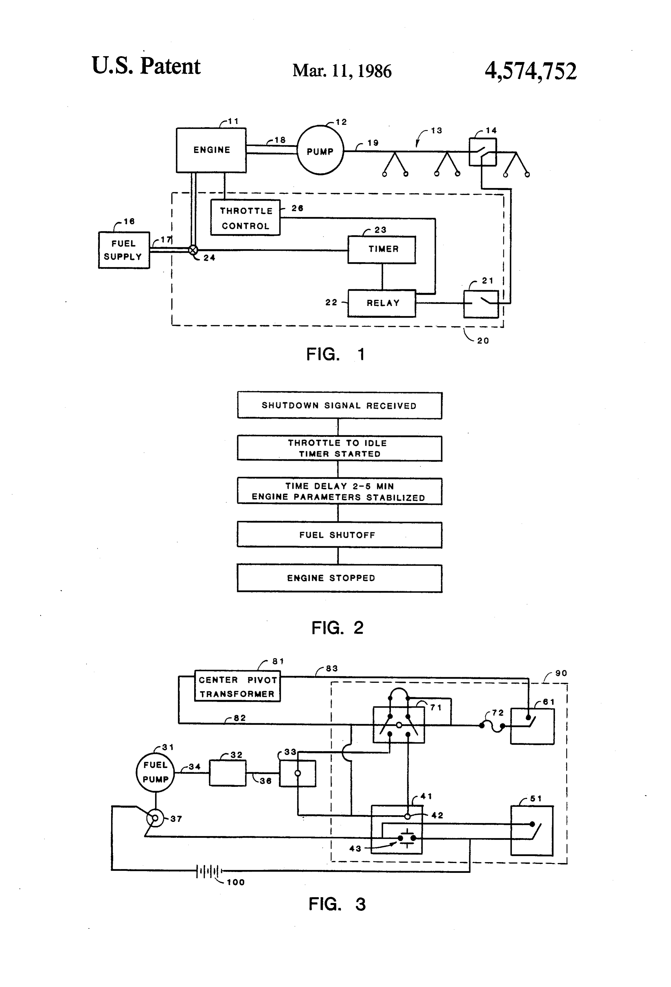
for an adjustable period of time before the engine is BRIEF DESCRIPTION OF THE DRAWINGS stopped. The device must be responsive to external conditions of both the direct and indirect type. It must The advantages of this invention will become appar be reliable and capable of being easily tested. The de ent upon consideration of the following detailed disclo vice should provide an adjustable idle operation time sure of the invention, especially when taken in conjunc which can be set for the particular engine and equip tion with the accompanying drawings, wherein: ment being powered by it. The device should be un 10 FIG. 1 is a schematic diagram of a center pivot irriga complicated in design, easily installed on existing en tion system including an internal combustion engine gines of numerous types, easily repaired, not subject to shutdown device in accordance with the present inven damage by vibration, and simple to manufacture. The tion.
instant invention is directed to all of these needs as well FIG. 2 is a diagrammatical representation of the se as to others as explained in the following summary. 15 quence of events occurring in the shutdown of an inter SUMMARY OF THE INVENTION nal combustion engine an accordance with the present invention.
It is a feature of the invention to provide an internal FIG. 3 is a schematic diagram of the electrical con combustion engine shutdown device. nections of a particular embodiment of the invention. It is another feature of the instant invention to pro 20 DESCRIPTION OF THE PREFERRED vide an inexpensive device useful in the controlled stop EMBODIMENT ping of an engine to prolong the life of the engine.
It is another feature of the instant invention to pro The apparatus of the instant invention is depicted vide an inexpensive device useful in the controlled stop generally in FIG. 1. As can be seen by reference to FIG. ping of an engine to prolong the life of the external 25 1, the invention is generally contained within the equipment powered by the engine. dashed lines 20 and includes a throttle control 26, a fuel It is another feature of the instant invention to pro shutoff valve 24, a timer 23, a relay 22, and test switch vide an internal combustion engine shutdown device 21. The apparatus 20 is connected to an internal com which is sensitive to a condition external to the condi bustion engine 11 and an external safety kill switch 14. tion of the engine. 30 For the purposes of understanding the device it has It is another feature of the instant invention to pro been shown in FIG. attached to and in association vide an internal combustion engine shutdown device with a center pivot irrigation system 13 which includes which will allow the operating parameters of the engine an engine 11 with a fuel supply 16, and a pivot irrigation to stabilize at a reduced engine speed before the engine pipe system 19 supported by a number of towers. The is completely stopped. 35 fuel supply 16 which is a tank or other supply of fuel is It is yet another feature of the instant invention to connected to the engine 11 by way of a fuel line 17 provide an internal combustion engine shutdown device having a control or shutoff valve 24 in the line 17 by to be used with a stationary engine. which the fuel can be shut off from the engine 11. The It is yet another feature of the instant invention to fuel shutoff valve 24 is of a type well known in the art provide an internal combustion engine shutdown device 40 and provides complete fuel shutoff with the activation to be used with a stationary engine powering a pump. of a solenoid or other type of fuel valve shutoff. It is a still further object of the invention to provide Continuing with reference to FIG. 1, it is to be noted an internal combustion engine shutdown device to be that throttle control 26 is attached to engine 11 by a used in a center pivot irrigation system. conventional method of a solenoid actuated rod at It is a still further object of the invention to provide 45 tached to the carburetor throttle on gasoline powered an internal combustion engine shutdown device to be engines and to the fuel pump on diesel powered engines. used in a center pivot irrigation system which will allow The throttle control 26 in either case is provided with the system pressures to be gradually reduced by operat an adjustable connecting link 32 as shown in FIG. 3 ing the engine at a reduced engine speed before the which allows the engine speed at idle to be adjusted for engine is completely stopped. 50 the particular conditions in the application employed. It is a still further object of the invention to provide Timer 23 in FIG. 1 could be any delay timer such as a an internal combustion engine shutdown device to be two position pneumatic timer, an R-C circuit or any used in a center pivot irrigation system employing a mechanical or electrical timer.
conventional kill switch. Relay 22 could be any relay which upon receipt of a These and other features and objects are attained 55 signal activates two succeeding functions. In the pre according to the instant invention by providing an inter ferred embodiment depicted in FIG. 3 the relay 71 is an nal combustion engine shutdown device having a relay, electrical double-pole contact magnetic switch relay. a fuel shutoff control, an engine throttle control, and an The relay is electrically connected between the external adjustable timer; in which the relay is connected to both condition switch 14 (as shown in FIG. 1 but not shown the throttle control and the timer and the timer is con 60 in FIG. 3) and both the timer 23 and throttle control 26. nected to the fuel shutoff control. Upon the receipt of A test switch 21 is provided to simulate the activation of an external signal such as the de-energizing of a conven external condition switch 14. Switch 14 is also known as tional "kill switch', the relay immediately reduces en a center "pivot safety switch'. Test switch 21 is also gine speed to idle by activating the throttle control. The known as a "system bypass switch' or "bypass switch'. adjustable timer is also started by the relay at the same 65 Test switch 21 is electrically connected between exter time. Once a pre-set time period has elapsed putting the nal condition switch 14 and relay 22. engine and or the external equipment in the proper state The general operation of the device will now be to be stopped, the timer activates the fuel shutoff con described with reference to FIGS. 1 and 2. With engine
Page 5
11 operating and having fuel supplied from fuel supply about two minutes is optimum for most applications. In 16 by way of supply line 17 with valve 24 open, engine any case the operator sets the adjustable timer 41 for 11 drives pump 12 by way of power takeoff 18. Pump 12 whatever delay is appropriate. At the end of the pre-set provides system 13 with pressure. Test switch 21 is delay period the timer 41 completes the fuel shutoff closed so that the misalignment switch 14 will trigger circuit, thus closing the fuel shutoff valve solenoid 37 relay 22. When there is a misalignment or some unsafe which stops the engine.
external condition of the irrigation system 13, switch 14 As can be seen with reference to FIG.3 a fuel shutoff activates relay 22 to activate the throttle control 26 and bypass switch 51 is provided to bypass the timer and timer 23 simultaneously. Throttle control 26 set the allow for the testing of the fuel shutoff valve 37 as well throttle or engine speed to idle. Timer 23 counts down 10 as the starting of the engine.
a pre-set time and then activates fuel shutoff valve 24. Additional test lights could be added to indicate if the The sequence of events as depicted in FIG. 2 summarize solenoids 33 and 37 have been fully activated. In that the general operation of the device. case, the lights let the operator see whether or not the The preferred embodiment as shown in FIG. 3 con fuel is completely shutoff and whether the throttle has forms with the general depiction in FIG. 1 but includes 15 been completely reduced to the lowest adjusted setting. the specific components used in conjunction with a Those lights (not shown) would have simple contact diesel engine providing power in a center pivot irriga switches which are activated by a complete travel of tion system. Referring now to FIG.3 it can be seen that the solenoid. The timer 41, relay 71, switch 51, switch in the preferred embodiment the throttle control 33 is an 61, fuse 72 and indicator lights (if any) are housed in a electrically operated solenoid driving a linkage rod 36 20 compact housing. It is contemplated that the circuit or attached to an adjustable threaded connector 32 (which portions of the circuit can be reduced to a printed cir could be a simple turnbuckle) and fuel pump control cuit board or any other method known in the art. rod 34. Since in the preferred embodiment power is The operation of the device will now be discussed provided by a diesel engine, the control of the engine with reference to FIGS. 1, 2, and 3 and in respect to the speed is accomplished by control of the fuel pump 31. 25 preferred embodiment. To start the system the test Throttle control 33 when activated pushes rod 34 by switch 61 is set to an off or open position. The timer way of adjuster 32 and rod 36 to slow the speed of the bypass switch 51 is set to allow fuel valve 37 to remain engine. Electrically actuated fuel shutoff valve 37 is open. The engine 11 is started and the manual throttle connected to engine battery 100 and timer 41. Fuel (not shown) on the engine is set at the operating RPM. shutoff valve 37 is an ordinary fuel shutoff valve well 30 Test switch 61 is set to an on or closed position and the known in the art. Battery 100 is normally a 12 or 24 volt timer bypass switch 51 is released. The throttle (not lead/acid battery well known in the art and is part of shown) is set to the desired idle position and the pump the engine electrical system. 12 is started. As the pivot system 13 operates correctly Some center pivot irrigation systems use electrical the engine 11 continues to run within its operating speed power and electrically driven pumps in which the sta 35 range. If there is a misalignment or if one or more of the tionary engine powers a generator which in turn pro pivot drive wheels become stuck, the pivot kill switch vides electrical power to run the system including both 14 (misalignment switch) de-energizes by releasing the the pump as well as the drive motors to move the sys relay 71 which makes contact with both the timer 41 tem itself. Other systems use an engine driven pump and and the throttle control 33. The throttle control 33 electric motors to move the tower mounted supply 40 reduces the engine speed to idle and the timer 41 counts pipes over the ground. In this later type of system a down a pre-set time until it actuates the fuel shutoff 37 source of high voltage electricity is available. thereby stopping the engine 11. A misalignment switch 14 (not shown in FIG. 3) is Although specific applications, materials, compo part of a center-pivot system and is connected to the 110 nents, connections, sequences of events, and methods volt electrical power supply from the center pivot 45 have been stated in the above description of the pre transformer. That switch 14 (FIG. 1) is normally ener ferred embodiment of the invention, other suitable ma gized until a misalignment occurs at which time electri terials, other applications, components and process cal power normally available from transformer 81 steps as listed herein may be used with satisfactory (FIG. 3) by way of circuit path 82 and 83 is ceased. results and varying degrees of quality. In addition, it Transformer electrical power holds a two pole mag 50 will be understood that various other changes in details, netic contact 71 (relay) open but when the misalignment materials, steps, arrangements of parts and uses which switch (not shown in FIG. 3) is triggered by a misalign have been herein described and illustrated in order to ment or tower stoppage or for whatever reason, circuit explain the nature of the invention will occur to and path 82 and 83 is opened. Relay 71 is then released. As may be made by those skilled in the art, upon a reading can be seen in FIG. 3 an on/off test switch 61 is pro 55 of this disclosure, and such changes are intended to be vided in circuit path 83 as well as fuse 72. included within the principles and scope of this inven Since relay 71 is connected to both timer 41 and tion as hereinafter claimed.
throttle control solenoid 33 which are electrically pow We claim:
ered by the engine battery, both are immediately actu 1. An internal combustion engine shutdown device ated. Throttle control 33 reduces engine speed to a 60 for the controlled stopping of an internal combustion pre-set adjustable setting. The turnbuckle adjustment 32 engine upon the receipt of a signal, the engine of the provides that pre-set engine speed. Timer 41 is also type having an ignition system, a fuel supply in fluid started. Timer 41 in the preferred embodiment is an communication with the engine and an engine speed off-delay pneumatic timer which can be adjusted for a control; the device comprising:
delay period of from zero to five xinutes. Although 30 65 a relay means for relaying the signal; to 45 seconds of operation at idle is probably sufficient, a timing means for determining a pre-set time period; in order to insure that the temperatures and pressures a throttle control means for controlling said engine are stabilized it is contemplated that a time period of speed control; and
Page 6
an engine stopping means for stopping the engine 10. The engine shutdown device as described in claim wherein said relay means is operably connected to 9 wherein said engine stopping means comprises an said timing means and to said throttle control electrically operated fuel shutoff valve operably con means and wherein said timing means is operably nected to said timing means.
connected to said engine stopping means and 9 wherein 11. The engine shutdown device as described in claim wherein said throttle control means is operably electrically said engine stopping means comprises an operated ignition shutoff switch operably connected to said engine speed control.
2. The engine shutdown device as described in claim connected between said engine ignition system and said 1 wherein said relay means comprises an electrical dou 10 timing means.
12. A method for the controlled stopping of an inter ble-pole relay. nal combustion engine upon the receipt of a signal, the 3. The engine shutdown device as described in claim engine of the type having a fuel supply in fluid commu 1 wherein said timing means comprises an off-delay nication with the engine and an engine speed control; pneumatic timer. the method comprising the steps of: 4. The engine shutdown device as described in claim 15 providing a relay means for relaying the signal; 1 wherein said engine stopping means comprises an a timing means for determining a pre-set time per electrically operated valve in fluid communication be iod; a throttle control means for controlling said tween the fuel supply and the engine. engine speed control; and an engine stopping 5. The engine shutdown device as described in claim means for stopping the engine wherein said relay 1 wherein said throttle control means comprises a sole 20 means is operably connected to said timing noid. means and to said throttle control means and 6. The engine shutdown device as described in claim wherein said timing means is operably connected 5 wherein said throttle control means further comprises to said engine stopping means and wherein said an adjustable rod operably connected between said 25 throttle control means is operably connected to solenoid and said engine speed control. said engine speed control; 7. The engine shutdown device as described in claim relaying the signal by the relay means to the timing 1 further comprising a test switch operably connected means to start the timing means; between said signal and said relay means. relaying the signal to the throttle control means to reduce the engine speed by slowing said engine 8. The engine shutdown device as described in claim speed control;
7 further comprising a fuse operably connected between delaying a pre-set period of time by use of the timing said test switch and said relay means. means; and 9. The engine shutdown device as described in claim stopping the engine by activating said engine stop 8 further comprising a fuel shutoff bypass switch opera ping means. s: k k k se bly connected to said electrically operated fuel valve, 35
Provenance
- Collection
- Cited prior art
- Original PDF
- patentimages.storage.googleapis.com →
- Filed
- 1984-10-15
- Pages
- 6
- Method
- pdftotext (the PDF's own text layer) + pdftoppm 300dpi page scans
- Source
- Google Patents bibliographic record
- Granted
- 1986-03-11
- Inventors
- Marvion E. Reichert, Jr.; William D. Simmerman
- Transcribed from
- patentimages.storage.googleapis.com →