patent · US5363828
Fuel vapor processing apparatus of internal combustion engine
15 November 1994
Page 1 — bibliographic record
United States Patent 19 11 Patent Number: 5,363,828 Yamashita et al. (45) Date of Patent: Nov. 15, 1994 54 FUEL VAPOR PROCESSINGAPPARATUS FOREIGN PATENT DOCUMENTS
OF INTERNAL COMBUSTON ENGINE
75 Inventors: Osao Yamashita, Tokai; Yasunori 3-17169 2/1991 Japan. Nakatsu, Aichi, both of Japan 40318267 11/1992 Japan ..................... .............. 123/518 Primary Examiner-E. Rollins Cross 73 Assignee: Aisan Kogyo Kabushiki Kaisha, Assistant Examiner-Thomas N. Moulis Ohbu, Japan Attorney, Agent, or Firm-Cushman, Darby & Cushman 21 Appl. No.: 92,821 (57) ABSTRACT In a fuel vapor processing apparatus of a fuel tank for an 22 Filed: Jul.19, 1993 internal combustion engine, fuel vapor in the fuel tank is 30 Foreign Application Priority Data supplied to a fuel vapor collecting canister filled with an absorbent, and is absorbed and collected therein, and
Jul. 22, 1992 JP Japan .................................. 4-195221 the absorbed fuel in the canister is introduced into the downstream of a suction air throttle valve in a suction 51 int. C. ............................................. F02M 25/08 air passage through a control valve. The fuel vapor 52 U.S. C. ................................ 123/520; 123/198 D processing apparatus comprises a three-way valve hav 58 Field of Search ............... 123/518, 519, 520, 521, ing three openings which are connected to an airport of 123/198 D the canister, an upper air chamber of the fuel tank, and
an air release port, a pressure sensor provided in such a manner that the pressure sensor is closer to the fuel tank
4,862,856 9/1989 Yokoe et al. ........................ 123/519 ates the three-way valve so as to communicate the air 4,949,695 8/1990 Uraniski et al... ... 123/520 port of the canister with the upper air chamber of the 5,056,494 10/1991 Kayanuma .......................... 123/519 fuel tank and to introduce a suction negative pressure 5,146,902 9/1992 Cook et al. .. ... 123/198 D into piping portions of the fuel vapor processing appara 5,158,054 10/1992 Otsuka ............................ 123/198 D tus through the control valve, so that when the pressure 5,191,870 3/1993 Cook ............................... 123/198 D in the piping portions reaches a predetermined value, 5,193,512 3/1993 Steinbrenner et al.......... 123/198 D the control unit closes the control valve, and that when 5,220,898 6/1993 Kidokoro et al. ... ... 123/520 a change of signals transmitted from the pressure sensor 5,259,353 1 1/1993 Nakai et al. .............. ... 123/520 in accordance with time thereafter exceeds a predeter 5,259,355 11/1993 Nakashima et al. ................ 123/520 mined range, the control unit judges it as abnormality.
5,267,470 12/1993 Cook ................................... 123/520 5,275,144 1/1994 Gross .............................. 123/198 D 2 Claims, 3 Drawing Sheets
SIGNAL OF ENGINE
ROTATIONAL SPEED
Page 2
Drawing sheet — no readable text.
Page 3
Drawing sheet — no readable text.
Page 4
Drawing sheet — no readable text.
Page 5
signals transmitted from the pressure sensor in accor
FUEL VAPOR PROCESSINGAPPARATUS OF dance with time thereafter exceeds a predetermined INTERNAL COMBUSTON ENGINE range, the control unit judges it as abnormality. Moreover, according to a second aspect of the inven
BACKGROUND OF THE INVENTION 5 tion, a fuel vapor processing apparatus of a fuel tank for 1. Industrial Field of the Invention an internal combustion engine, in which fuel vapor in The present invention relates to a fuel vapor process the fuel tank is supplied to a fuel vapor collecting canis ing apparatus which is able to detect abnormality of a ter through a tank internal pressure control valve, and is fuel tank or the like in an automobile. absorbed and collected therein, and the absorbed fuel in 10 the canister is introduced into the downstream of a 2. Description of Related Art
Japanese Utility Model Unexamined Publication No. suction air throttle valve in a suction air passage 3-17169 discloses a fuel vapor purge system in a fuel through a control valve, comprises a three-way valve vapor processing apparatus of a fuel tank in which fuel having three openings which are connected to a dia vapor in the fuel tank is supplied to a fuel vapor collect 15 phragm chamber of the tank internal pressure control ing canister and absorbed/collected by an absorbent valve, the downstream of the suction air throttle valve filled in the canister, and the absorbed fuel in the canis in the suction air passage, and an air release port, respec ter is introduced, via a purge line, to the downstream of tively, an open and close valve connected to an airport a suction air throttle valve in a suction air passage. In of the canister, a pressure sensor provided in such a this publication, there is proposed a self-diagnosis de manner that the pressure sensor is closer to the fuel tank vice of the fuel vapor purge system in the fuel vapor 20 than the control valve is, and a control unit which oper processing apparatus of the fuel tank, comprising means ates the three-way valve so as to communicate the dia for judging whether or not the fuel vapor purge system phragm chamber of the tank internal pressure control is in a range for fuel purge, means for detecting the valve with the downstream of the suction air throttle pressure in the purge line, and means for judging valve in the suction air passage, to close the open and whether the system is normal or abnormal, on the basis 25 of the pressure in the purge line which pressure is close valve, and to introduce a suction negative pres sure into piping portions of the fuel vapor processing judged to be in the fuel-purge range or out of the range, apparatus through the control valve, so that when the by use of detection signals produced from the detecting pressure in the piping portions reaches a predetermined leaS.
value, the control unit closes the control valve, and that
In the above-described conventional technique, self 30 when diagnosis whether or not cracks exist in the purge line is sensorainchange of signals transmitted from the pressure accordance with time thereafter exceeds a carried out while an airport of the canister is kept open to communicate with the atmosphere. Consequently, it predetermined normality.
range, the control unit judges it as ab is impossible to detect abnormalities in a main body of Furthermore, according to a third aspect of the in the canister and the fuel tank. There has conventionally 35 vention, a fuel vapor processing apparatus of a fuel tank been a problem that abnormality all over the fuel vapor for an internal processing apparatus and piping portions cannot be in the fuel tankcombustion engine, in which fuel vapor is supplied to a fuel vapor collecting detected.
canister through a tank internal pressure control valve,
SUMMARY OF THE INVENTION 40 and is absorbed and collected therein, and the absorbed It is therefore an object of the present invention to fuel in the canister is introduced into the downstream of provide a fuel vapor processing apparatus which can a suction air throttle valve in a suction air passage Solve the above-mentioned problem and can detect through a control valve, comprises a solenoid for open abnormality by shutting off a whole of a fuel tank, the ing the tank internal pressure control valve, an open and fuel vapor processing apparatus and piping portions at 45 close valve connected to an air port of the canister, a the time of self-diagnosis. pressure sensor provided in such a manner that the In order to achieve the above object, according to a pressure sensor is closer to the fuel tank than the control first aspect of the present invention, a fuel vapor pro valve is, and a control unit which operates the solenoid cessing apparatus of a fuel tank for an internal combus so as to open the tank internal pressure control valve, to tion engine, in which fuel vapor in the fuel tank is sup 50 close the open and close valve, and to introduce a suc plied to a fuel vapor collecting canister filled with an tion negative pressure into piping portions of the fuel absorbent, and is absorbed and collected therein, and vapor processing apparatus through the control valve, the absorbed fuel in the canister is introduced into the so that when the pressure in the piping portions reaches downstream of a suction air throttle valve in a suction a predetermined value, the control unit closes the con air passage through a control valve, comprises a three 55 trol valve, and that when a change of signals transmit way valve having three openings which are connected ted from the pressure sensor in accordance with time to an air port of the canister, an upper air chamber of thereafter exceeds a predetermined range, the control the fuel tank, and an air release port, respectively, a unit judges it as abnormality.
pressure sensor provided in such a manner that the In the present invention, abnormality detection is pressure sensor is closer to the fuel tank than the control 60 basically carried out while the engine is on. valve is, and a control unit which operates the three In a structure according to the first aspect of this way valve so as to communicate the air port of the invention, with the engine being on, the control unit canister with the upper air chamber of the fuel tank and operates the three-way valve so as to communicate the to introduce a suction negative pressure into piping airport of the canister with the upper air chamber of the portions of the fuel vapor processing apparatus through 65 fuel tank, and also opens the control valve so that a the control valve, so that when the pressure in the pip suction-pipe negative pressure at the downstream of the ing portions reaches a predetermined value, the control suction air throttle valve in the suction air passage is unit closes the control valve, and that when a change of introduced into piping portions of the fuel vapor pro
Page 6
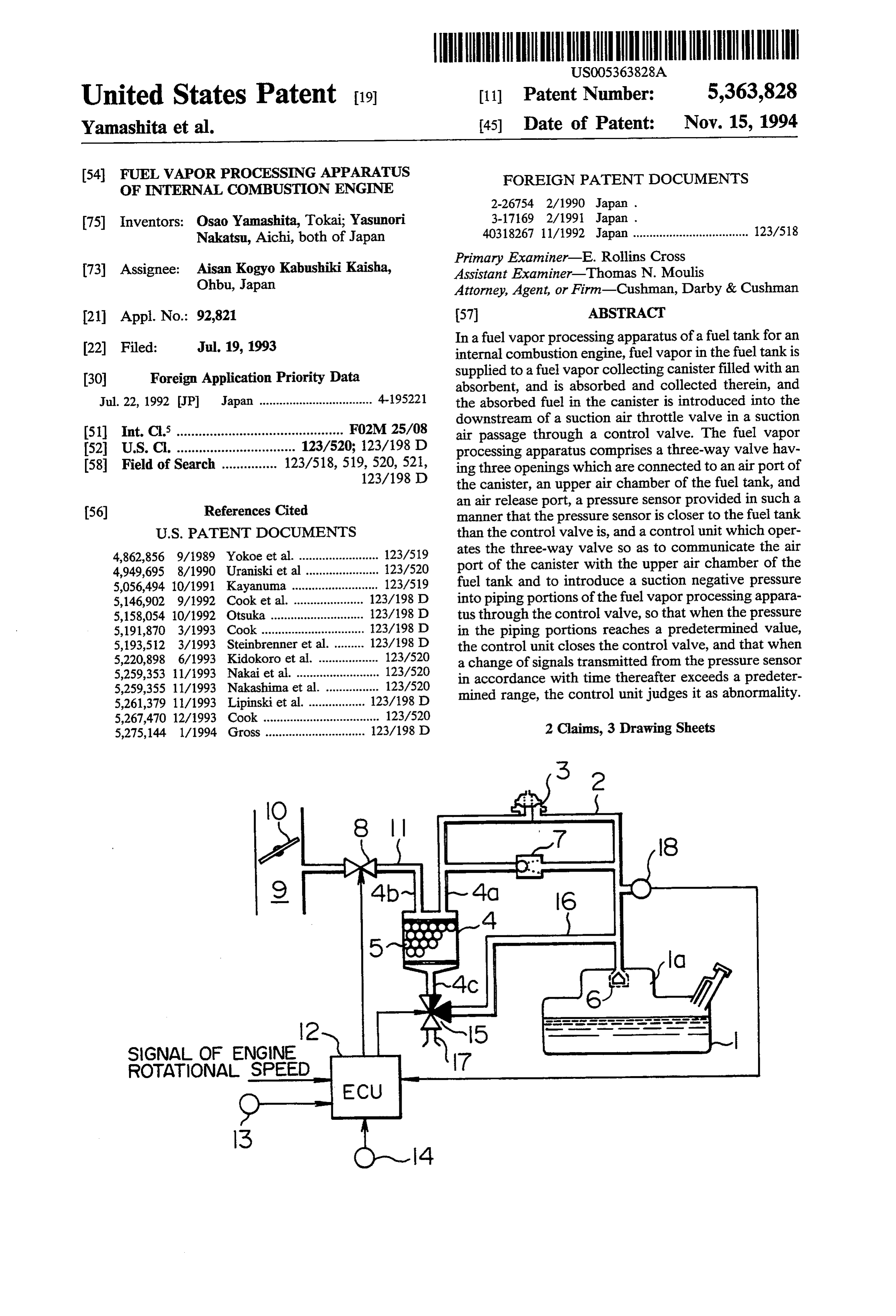
cessing apparatus. When the pressure in the piping por The tank internal pressure control valve 3 is of the tions reaches a predetermined negative pressure, the known structure which includes a diaphragm. When control unit closes the control valve. If any of the pip the pressure in the fuel tank 1 is at a predetermined ing portions and the like has cracks and leaks the air, the value or less, the control valve 3 is closed, and when it pressure in the piping portions is drastically raised, and exceeds the predetermined value, the control valve 3 is signals from the pressure sensor are abruptly changed. opened, to thereby communicate the upper air chamber Consequently, the control unit monitors a change of the 1a and the tank port 4a with each other. signals in accordance with time and judges whether the A check valve 7 of the known structure for prevent abnormality exists or not. ing breakage of the fuel tank due to negative pressure is In a structure according to the second aspect of this O connected in parallel to the tank internal pressure con invention, with the engine being on, the control unit trol valve 3, as shown in FIG. 1. The check valve 7 is operates the three-way valve so as to introduce a suc opened when the pressure in the fuel tank 1 is not more tion-pipe negative pressure at the downstream of the than a predetermined value.
suction air throttle valve in the suction air passage into A control valve 8 is inserted in a purge passage 11 the diaphragm chamber of the tank internal pressure 15 which connects the purge port 4b of the canister 4 with control valve, thereby opening the tank internal pres the downstream of a suction air throttle valve 10 of a sure control valve, and the control unit also closes the suction air passage 9. Duty-ratio control of the control open and close valve connected to the air port of the valve 8 is performed by a control unit 12 so as to control canister. At the same time, the control unit opens the the purge flow rate.
control valve so as to introduce the suction-pipe nega 20 The control unit 12 calculates an appropriate purge tive pressure into the piping portions of the fuel vapor flow rate in accordance with engine operating condi processing apparatus. tions during normal operation on the basis of a signal of When the pressure in the piping portions reaches a engine rotational speed and signals from a suction-pipe predetermined value, the control unit closes the control negative pressure sensor 13 and an exhaust-system air valve. 25 fuel ratio (O2) sensor 14. Then, the control unit 12 regu After that, the control unit monitors signals from the lates the duty ratio of the control valve 8. pressure sensor. When a change of the signals in accor A three-way valve 15 has three openings which are dance with time exceeds a predetermined range, the connected to the airport 4c of the canister 4, to a bypass control unit judges it as abnormality that the piping passage 16 communicated with the upper air chamber portions or the like leak the air. 30 1a of the fuel tank 1, and to an air release port 17, as A structure according to the third aspect of the in shown in FIG. 1. In this illustration, the opening con vention is similar to the structure according to the sec nected to the bypass passage 16 is closed. ond aspect of the invention in many respects. Therefore, There is also provided a pressure sensor 18 which the function will be described in the preferred embodi detects a pressure in the vapor passage 2 and outputs an ment below. 35 electric signal of the detected pressure to the control unit.
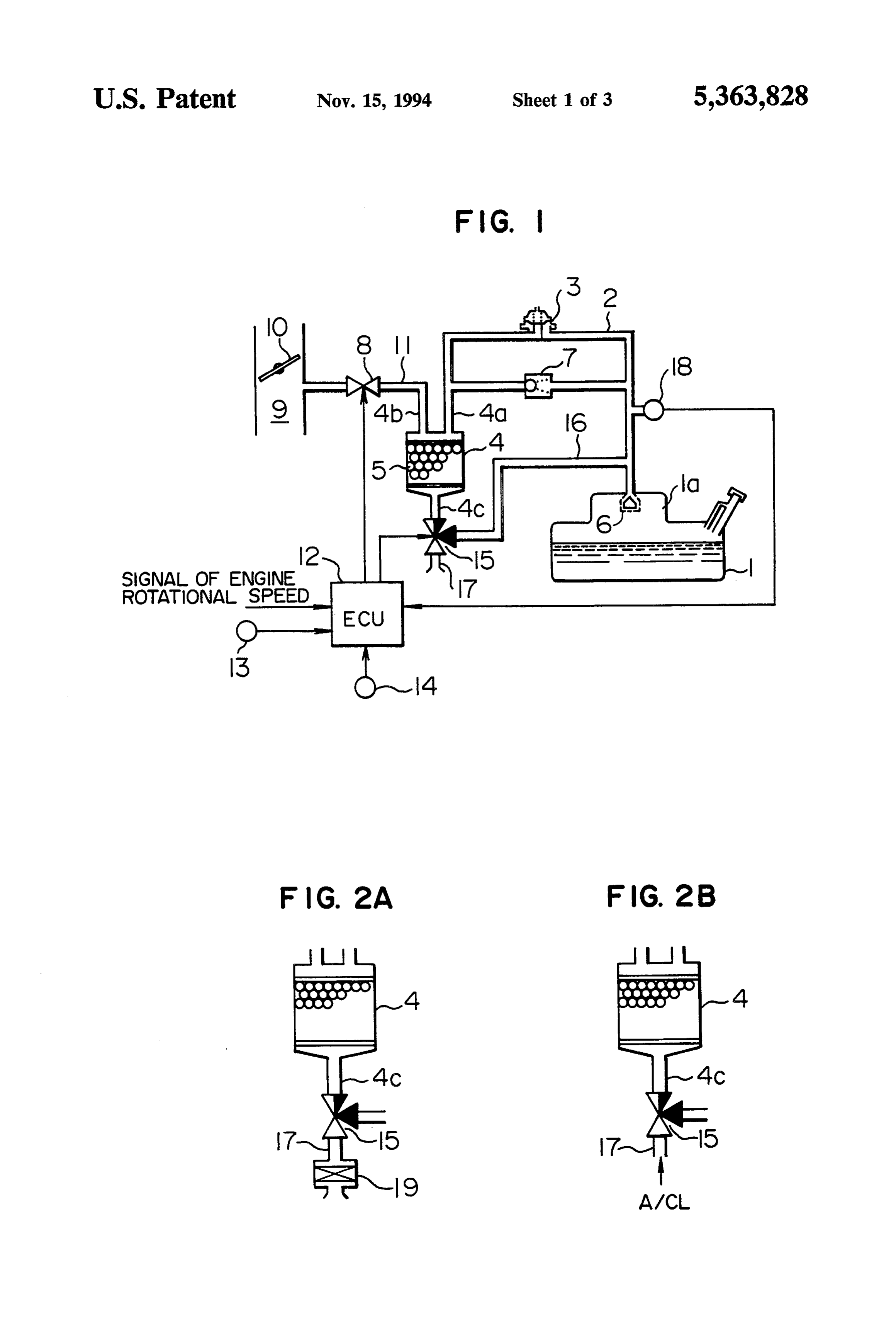
BRIEF DESCRIPTION OF THE DRAWINGS In the first embodiment, abnormality detection of a FIG. 1 is a diagram showing a structure of a first fuel vapor processing apparatus is carried out in the embodiment according to the present invention; following manner.
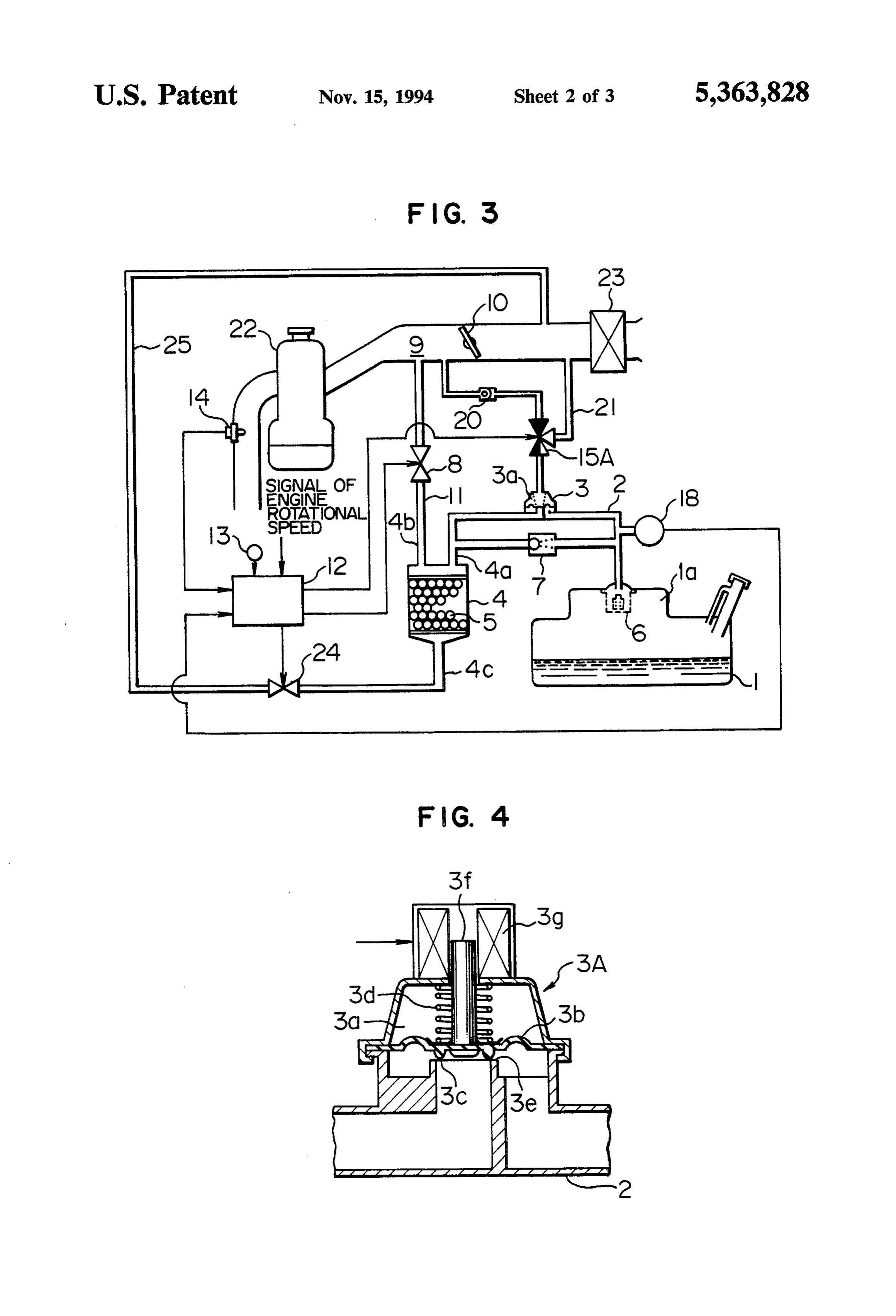
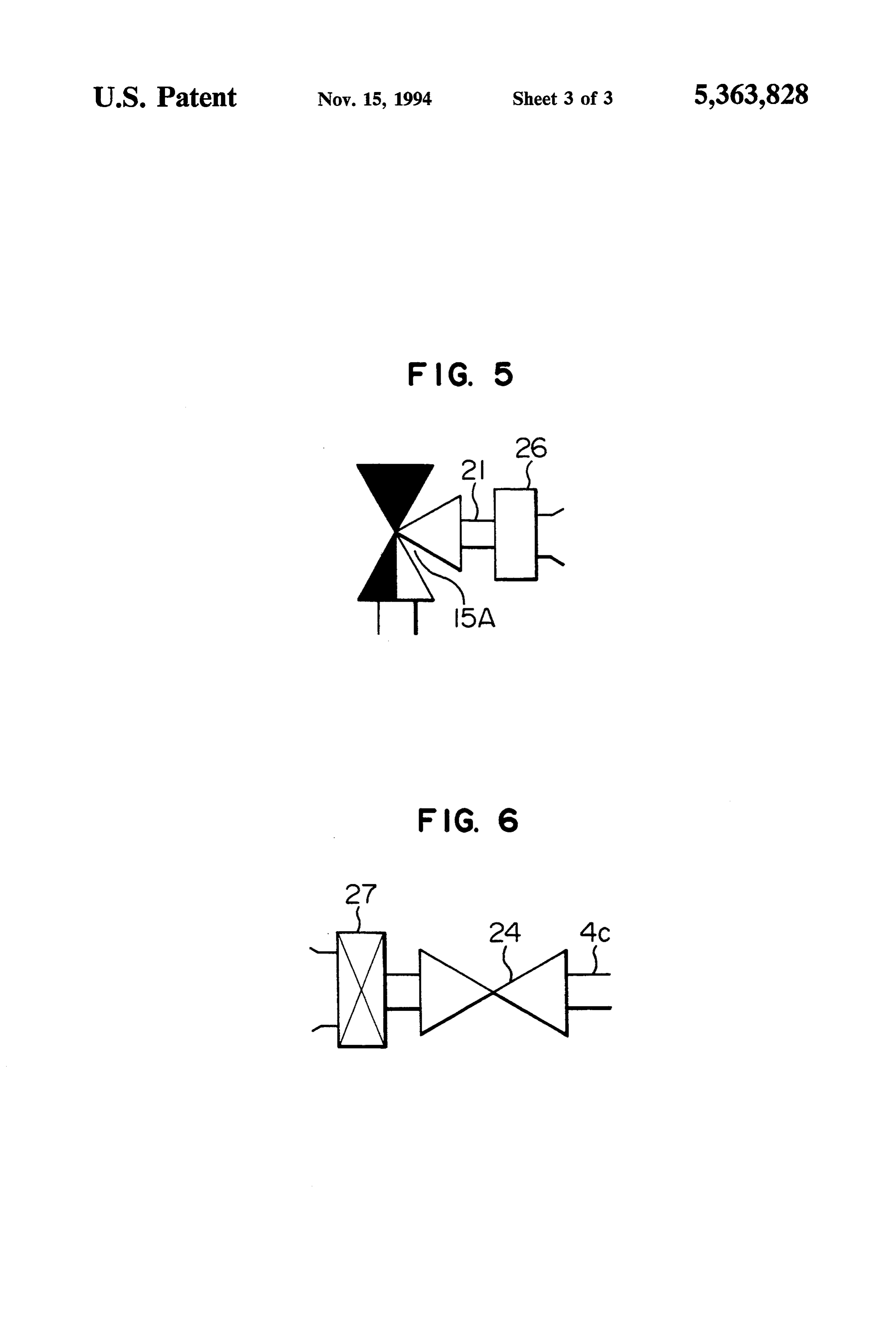
FIGS. 2A and 2B are partial modification diagrams in This abnormality detection is performed while the which the first embodiment shown in FIG. 1 is partially engine is on. First, the control unit 12 switches the modified; three-way valve 15 so as to communicate the airport 4c FIG. 3 is a diagram showing a structure of a second with the bypass passage 16 and also to close the air embodiment according to the invention; release port 17. At the same time, the control valve 8 is FIG. 4 is a vertical cross-sectional view showing a 45 opened under the duty-ratio control by the controll unit tank internal pressure control valve in a third embodi 12, and a suction-pipe negative pressure is introduced ment according to the invention; into the purge passage 11.
FIG. 5 is a partial modification diagram in which the The introduced negative pressure is detected by the embodiment shown in FIG. 3 is partially modified; and negative pressure sensor 18 and read by the control unit FIG. 6 is another partial modification diagram in 50 12. When it reaches a predetermined negative pressure, which the embodiment shown in FIG. 3 is partially the control unit 12 closes the control valve 8. modified. In this condition, all the piping in the fuel vapor pro cessing apparatus including the fuel tanki and the canis
DETALED DESCRIPTION OF THE ter 4 are communicated with one another. The control PREFERRED EMBODIMENTS 55 valve 8 and the three-way valve 15 shut the communi A first embodiment shown in FIG. 1 illustrates a cation with the outside, and thus, all the piping are structure according to the first aspect of the present hermetically sealed. - invention. Referring to FIG. 1, a fuel tank 1 for a vehi Therefore, if none of these pipes have cracks and cle includes an upper air chamber 1a, and a vapor pas leak, the sealed negative pressure is seldom decreased, sage 2 communicates the upper air chamber 1a with a and even if there is a change, it is merely a pressure tank port 4a of a canister 4 via a tank internal pressure change owing to a temperature change. control valve 3. If the piping have cracks or the like and leak, a An absorbent 5 composed of active carbon is filled in change in the negative pressure in accordance with time the canister 4. The canister 4 has a purge port 4b and an exceeds a predetermined range, and consequently, the airport 4c. A float valve 6 is provided on an opened end 65 control unit 12 judges it as abnormality. portion of the vapor passage 2 inside of the upper air In the first embodiment, when the suction-pipe nega chamberla, and the float valve 6 is closed, for example, tive pressure is introduced at the time of abnormality when the vehicle turns over. detection the pressure change is monitored by the con
Page 7
trol unit 12 through the signals from the pressure sensor leak due to cracks or the like, signals from the pressure 18, and compared with a pressure change during normal sensor 18 are abruptly changed in accordance with operation, so that abnormality of the control valve 8 time, so that when the pressure change exceeds a prede and the three-way valve 15 can be also detected. termined range, the control unit 12 judges it as abnor When abnormality detection is finished, the control mality of the piping portions.
valve 8 is operated under duty-ratio control after the In this manner, abnormality in all the piping portions three-way valve 15 recovers the condition shown in of the fuel vapor processing apparatus is detected. FIG. 1. In this manner, fuel vapor is prevented from In the second embodiment, during abnormality detec being released into the atmosphere through the air port tion, the three-way valve 15A is switched to close the 4c of the canister 4. 10 open and close valve 24 and to operate the control FIGS. 2A and 2B illustrate partially modified em valve 8 under duty-ratio control, thereby introducing bodiments of the first embodiment shown in FIG. 1. the suction-pipe negative pressure into the piping por FIG. 2A shows the case where a filter 19 is inserted in tions of the fuel vapor processing apparatus. When a the air release port 17 of the three-way valve 15, and change of the negative pressure until the introduced FIG. 2B shows the case where the air release port 17 of 15 negative pressure reaches a predetermined value is the three-way valve 15 is connected to an air cleaner monitored by the control unit 12 on the basis of outputs A/CL. from the pressure sensor 18, it is also possible to detect FIG. 3 shows a second embodiment according to the whether the open and close valve 24, the three-way present invention corresponding to a structure accord valve 15A, the tank internal pressure control valve 3, ing to the second aspect of the invention. 20 the control valve 8 and so forth are abnormal or not. In this drawing, component parts indicated by refer This isjudged by the control unit 12 when the change of ence numerals 1 (a fuel tank) to 14 (an air-fuel ratio (O2) the negative pressure is compared with a pressure sensor) have substantially the same functions as those of change during normal operation.
the first embodiment indicated by common reference When abnormality detection is finished, the open and numerals in FIG. 1 so that the explanation thereof will 25 close valve 24 is opened, and thereafter, the control be omitted. valve 8 is operated under the duty-ratio control, and the A three-way valve 15A has three openings which are three-way valve 15A is switched to recover the condi connected to a diaphragm chamber 3a of a tank internal tion shown in FIG. 3.
pressure control valve 3, to the downstream of a suction FIG. 4 illustrates an essential portion of a third em air throttle valve 10 of a suction air passage 9 via a 30 bodiment according to the present invention which is check valve 20, and to an air release port 21 connected obtained by partially modifying the embodiment shown to the upstream of the suction air throttle valve 10. in FIG. 3. In the third embodiment, the three-way valve FIG. 3 further shows an engine 22 and an air cleaner 15A and the check valve 20 in the second embodiment 23 which is installed in an upstream portion of the suc are not used, and the tank internal pressure control tion air passage 9. An open and close valve (a solenoid 35 valve 3 is substituted by a tank internal pressure control valve) 24 operated by a control unit 12 is inserted in a valve 3A shown in FIG. 4. This third embodiment passage 25 which connects an airport 4c of a canister 4 corresponds to the third aspect of the invention. to the upstream of the suction air throttle valve 10 of the The tank internal pressure control valve 3A com suction air passage 9. prises a diaphragm 3b integrally formed with a valve In the second embodiment shown in FIG. 3, abnor body 3c, a spring 3d provided in a diaphragm chamber mality detection is carried out in the following manner. 3a so as to urge the diaphragm 3b downwardly, a valve This abnormality detection is performed while the seat 3e which functions cooperatively with the valve engine is on. First, with the engine being on, the three body 3c, and a solenoid 3g which upwardly attracts a way valve 15A is switched from the illustrated condi plunger 3fattached to the diaphragm 3b. tion so as to communicate the diaphragm chamber 3a 45 During normal operation, the solenoid 3g is not mag with the downstream of the suction air throttle valve 10 netized. The pressure in a fuel tank 1 is applied to the of the suction air passage 9 and also to close the air lower surface of the diaphragm 3b through a vapor release port 21. passage 2, and when the applied pressure exceeds a As a result, a suction-pipe negative pressure is applied predetermined value, the diaphragm 3b is moved up to the diaphragm chamber 3a through the check valve 50 wardly against the force of the spring 3d, and the tank 20 so that the tank internal pressure control valve 3 is internal pressure control valve 3A is opened. opened to communicate an upper air chamber 1a of the As a result, fuel vapor flows from an upper air cham fuel tank 1 with the canister 4 via a vapor passage 2. ber 1a of the fuel tank 1 into a canister 4 through the When the control unit 12 switches the three-way vapor passage 2, and is absorbed and collected by an valve 15A in this manner, it simultaneously closes the 55 absorbent 5.
open and close valve 24, and a control valve 8 is opened At the time of abnormality detection, with the engine under duty-ratio control. Then, the suction-pipe nega being on, a control unit 12 supplies an excitation current tive pressure is applied, via the control valve 8, to pip to the solenoid 3g of the tank internal pressure control ing portions of a fuel vapor processing apparatus includ valve 3A so that the solenoid 3g attracts the plunger 3f ing the fuel tank 1 and the canister 4. upwardly against the force of the spring 3d, to thereby The control unit 12 detects a negative pressure in open the tank internal pressure control valve 3A and the these piping portions on the basis of a signal from a control unit 12 also closes an open and close valve 24. pressure sensor 18. When it reaches a predetermined At the same time, a control valve 8 is opened cunder negative pressure, the control unit 12 closes the control duty-ratio control, and a suction-pipe negative pressure valve 8, to thereby keep the pressure in the piping por 65 is introduced into piping portions of a fuel vapor pro tions negative. cessing apparatus.
After that, signals from the pressure sensor 18 are The control unit 12 checks signals from a pressure monitored by the control unit 12. If the piping portions sensor 18. When the pressure in the piping portions
Page 8
reaches a predetermined negative pressure, the control duce a suction negative pressure into piping por unit 12 closes the control valve 8, to thereby keep the tions of the fuel vapor processing apparatus pressure in the piping portions negative. through said control valve, so that when the pres The control unit 12 monitors signals from the pres sure in said piping portions reaches a predeter sure sensor 18 after that. If the piping portions leak due mined value, the control unit closes the control to cracks, the pressure is drastically raised, and signals valve, and that when a change of signals transmit from the pressure sensor 18 are abruptly changed. ted from the pressure sensor in accordance with Therefore, when the pressure change in accordance time thereafter exceeds a predetermined range, the with time exceeds a predetermined range, the control control unit judges it as abnormality. unit 12 judges it as abnormality of the piping portions. 10 2. A fuel vapor processing apparatus of a fuel tank for FIG. 5 illustrates an example in which the air release an internal combustion engine, in which fuel vapor in port 21 of the three-way valve 15A in the second em the fuel tank is supplied to a fuel vapor collecting canis bodiment shown in FIG. 3 is communicated with the ter through a tank internal pressure control valve, and is atmosphere through an air filter 26 in place of the air absorbed and collected therein, and the absorbed fuel in cleaner 23 in the suction air passage. 15 the canister is introduced into the downstream of a Further, FIG. 6 illustrates an example in which the suction air throttle valve in a suction air passage atmospheric air side of the open and close valve 24 through a control valve, connected to the air port 4c of the canister 4 in the said fuel vapor processing apparatus comprising: second embodiment shown in FIG. 3 is not communi a three-way valve having three openings which are cated with the suction air passage 9 but opened toward connected to a diaphragm chamber of the tank the atmosphere through an air filter 27. internal pressure control valve, the downstream of According to the present invention of the above the suction air throttle valve in the suction air pas described structure, abnormality in all the piping por sage, and an air release port; tions of the fuel vapor processing apparatus including an open and close valve connected to an air port of the fuel tank and the canister can be detected. 25 the canister;
What is claimed is: a pressure sensor provided in such a manner that said 1. A fuel vapor processing apparatus of a fuel tank for pressure sensor is closer to the fuel tank than said an internal combustion engine, in which fuel vapor in control valve is; and the fuel tank is supplied to a fuel vapor collecting canis a control unit which operates said three-way valve so ter filled with an absorbent, and is absorbed and col 30 as to communicate the diaphragm chamber of the lected therein, and the absorbed fuel in the canister is tank internal pressure control valve with the down introduced into the downstream of a suction air throttle stream of the suction air throttle valve in the suc valve in a suction air passage through a control valve, tion air passage, to close said open and close valve, said fuel vapor processing apparatus comprising: and to introduce a suction negative pressure into a three-way valve having three openings which are 35 piping portions of the fuel vapor processing appa connected to an air port of the canister, an upper ratus through said control valve, so that when the air chamber of the fuel tank, and an air release port; pressure in said piping portions reaches a predeter a pressure sensor provided in such a manner that the mined value, the control unit closes the control pressure sensor is closer to the fuel tank than said valve, and that when a change of signals transmit control valve is; and ted from the pressure sensor in accordance with a control unit which operates said three-way valve so time thereafter exceeds a predetermined range, the as to communicate the air port of the canister with control unit judges
it as: abnormality.
the upper air chamber of the fuel tank and to intro
Provenance
- Collection
- Cited prior art
- Original PDF
- patentimages.storage.googleapis.com →
- Filed
- 1993-07-19
- Pages
- 8
- Method
- pdftotext (the PDF's own text layer) + pdftoppm 300dpi page scans
- Source
- Google Patents bibliographic record
- Granted
- 1994-11-15
- Inventors
- Osao Yamashita; Yasunori Nakatsu; Aisan Industry Co Ltd
- Transcribed from
- patentimages.storage.googleapis.com →