patent · US5123836
Method for the combustion treatment of toxic gas-containing waste gas
23 June 1992
Page 1 — bibliographic record
United States Patent (19) 11) - Patent Number: 5,123,836 Yoneda et al. (45. Date of Patent: Jun. 23, 1992 54 METHOD FOR THE COMBUSTION 3,755,990 9/1973 Hardison ............................... 55/240 TREATMENT OF TOXIC GAS-CONTAINING 3,954,945 5/1976 Lange et al. . 423/337 WASTE GAS 4,048.290 9/1977 Lee ................... ... 423A336 4,108,964 8/1978 Kiratel et al. . ... 423/337 75) Inventors: Noriyuki Yoneda, Tokyo: Hidehiko 4,276.274 5/1981 Heckel ......... ... 423/337 Kudoh, Yokohama; Norio Iwamoto, 4,292,290 9/1981 Tunison ........ ... 423/336 Yokohama; Munekazu Nakamura, 4,555,389 11/1985 Soneta et al. ... ... 423/337 Yokohama; Chiaki Kojima, 4,801,437 l/1989 Konayaga et al. ... ... 423/337 Yokohama; Kunio Kaneko, 4,881,952 11/989 Masaru ...................................... 55/l 4,908,191 3/1990 Boidish et al. 423A20
Yokohama; Yoshifumi Mori, Chiba; 4,973,451 1 1/1990 Vickery .................................. 431/5 Hideto Ishikawa, Yokohama; Hiroji
Kawai, Yokohama, all of Japan FOREIGN PATENT DOCUMENTS 73) Assignee: Chiyoda Corporation, Japan 61-93310 5/1986 Japan ................................... 423/337 (21) Appl. No.: 386,639 Primary Examiner-Gary P. Straub Assistant Examiner-Peter T. DiMauro 22 Filed: Jul. 31, 1989 Attorney, Agent, or Firm-Lorusso & Loud 30 Foreign Application Priority Data
Jul, 29, 1988 (JP Japan ................................ 63-900.50
Sep. 2, 1988 JP Japan ................................ 63-218389 A method and apparatus for the combustion treatment Sep. 16, 1988 (JP) Japan ... 63-23787 of a toxic gas which forms microparticles by combus Oct. 11, 1988 (JP) Japan ... ... 63-255614 tion are disclosed wherein the toxic gas is subjected to Nov. 11, 1988 (JP) Japan ... 63-284930 a combustion treatment in a specific combustion furnace Jul. 21, 1989 JP Japan .................................. 1.189351 where the combustion gas formed is brought into 51 Int. Cl. ........................ F23D 14/00; F23G 7/06; contact with an aqueous film flowing downwards on COB 13/20; B01D 47/00 the inner wall of the furnace from the upper end portion 52 U.S. Cl. ........................................ 431/5; 423/210; thereof to the lower end portion thereof or with a 423/337; 423/DIG. 20; 10/215; 110/216; cooled surface, and then optionally with aqueous drop 10/344 lets dispersed in the interior space of the furnace. The (58) Field of Search ........... 423/337, DIG. 20, 210 E; water captures the microparticles formed by combus 55/240, 431/5, 121, 19; 110/216, 215,344; tion of the toxic gas and is discharged out of the furnace 261/DIG. 9 as a mixed flow with the combustion gas thus treated, (56) References Cited and optionally the mixed flow is successively treated in a gas-liquid separator.
2,224, 30 12/1940 Arnold .................................. 431/9 22 Claims, 10 Drawing Sheets
Page 2
Drawing sheet — no readable text.
Page 3
Drawing sheet — no readable text.
Page 4
Drawing sheet — no readable text.
Page 5
Drawing sheet — no readable text.
Page 6
Drawing sheet — no readable text.
Page 7
Drawing sheet — no readable text.
Page 8
Drawing sheet — no readable text.
Page 9
Drawing sheet — no readable text.
Page 10
Drawing sheet — no readable text.
Page 11
Drawing sheet — no readable text.
Page 12
example, contained in smoke dusts. Accordingly, it is
METHOD FOR THE COMBUSTION TREATMENT extremely difficult to remove these microparticles com OF TOXIC GAS-CONTAINING WASTE GAS pletely from the combustion gas unlike the removal of larger particles. In the prior art combustion methods as
BACKGROUND OF THE INVENTION 5 mentioned above, air is used as a combustion-supporting 1. Field of the Invention gas for burning the toxic gas and a stream of air is blown The present invention relates to a method and appara into the combustion furnace along the wall thereof in tus for the combustion treatment of a waste gas contain order to protect the surface of the inner wall from de ing toxic gas from electronics and semiconductor indus 10 posit of such microparticles, simultaneously with form tries for detoxicating such waste gas. More particularly, ing an air flow of a high linear velocity towards an exit the present invention relates to a method and apparatus of the furnace to entrain the formed microparticles in for the combustion treatment of a waste gas containing the exhaust gas to be discharged out of the combustion a toxic gas which, on combustion, is oxidized to form furnace. The exhaust gas from the furnace is then intro microparticles. The waste gas is subjected to a combus duced into a wet-type dust-removing apparatus in tion treatment in a furnace where the toxic gas is oxida 5 stalled outside the furnace where the microparticles are tively burnt and the resultant microparticles are ab captured and separated from the combustion gas which sorbed in an aqueous film or droplets, and is then dis can now be exhausted safely.
charged out of the furnace together with water absorb However, there are a number of drawbacks to be ing the microparticles without permitting the formation 20 overcome also in such an air combustion method. As of any deposit of the microparticles on the inner wall of the waste gas has to be treated in two steps with a com the furnace. bustion furnace and a wet-type dust-removing appara 2. Description of the Prior Art: tus, such a method is not efficient in operation and needs In electronics and semiconductor industries, a waste a large space for installation. Further, the removal rate gas containing gaseous toxic substances represented by of solid microparticles in the conventional wet-type arsine (AsH3), phosphine (PH3), diborane (B2H6), 25 dust-removing apparatus is inherently not so high. As monosilane (SiH4), etc. is formed in the steps for manu the solid microparticles are captured outside the com facturing semi-conductors. Since such waste gas is bustion furnace, the microparticles have to be dis highly toxic to humans, complete elimination of such charged entirely out of the furnace together with the toxic substances contained in the waste gas is necessary exhaust gas. However, it is extremely difficult to dis prior to exhaust of the waste gas to atmosphere. 30
Various methods are known for effectively eliminat charge the microparticles entirely from the furnace ing or detoxicating such toxic substances, such as a since they tend to deposit on the inner wall of the com combustion method and an adsorption method. Among bustion furnace. In the prior art methods, therefore, it is these methods, the adsorption method is easy in opera proposed that a stream of air having a relatively high linear velocity is compulsorily formed in the furnace tion and thus employed conventionally to detoxicate 35 towards an exit thereof to prevent deposit of the mi the waste gas, adsorbed onto an adsorbent so that the croparticles on the inner wall of the furnace. The for waste gas thus treated can safely be exhausted from the mation of a stream of air having such a high linear ve production system. In this adsorption method, how locity is not only economically disadvantageous but still ever, the used adsorbent contains the toxic substances and so has to be brought to a complicated secondary unsatisfactory to protect the inner wall completely from treatemnt for detoxicating it. Further, a lot of replace deposit of the microparticles. Thus, a small amount of the microparticles is permitted to deposit on the inner ment or activation of the adsorbent are required during wall even in case of using a stream of air having a very the operation. Accordingly, this adsorption method necessitates further treatment and replacements of ad high linear velocity. The amount of the microparticles sorbent and so cannot be said to be economically suit 45 deposited on the inner wall becomes larger evenly or able. locally with the lapse of time. Accordingly, a large On the other hand, the combustion method contem amount of the deposit built up on the inner wall will plates oxidative decomposition of the toxic substances eventually be dropped as a lump irregularly from time in the waste gas under combustion conditions whereby to time from the inner wall, and as a result of this phe the gaseous toxic substances are oxidatively converted 50 nomenon, the operating conditions of the combustion into solid microparticle in the form of oxides and can be furnace, especially the pressure condition for combus removed from the gaseous substances. Such combustion tion significantly fluctuate to the extent of preventing method is known, for example, in Japanese Laid-open complete combustion of the toxic gas. What is more, Patent Applin. Nos. Sho. 62-134414 and 62-152517. As deposit of the microparticles on the inner wall causes no replacements are needed for the combustion method, 55 corrosion of the furnace.
in case of mass treatment of waste gas, the combustion In such air combustion methods, the extent of the method is superior. flame stably existing in the furnace is extremely narrow Among the gaseous toxic substances, for example, relative to the flow rate of the waste gas so that the arsine is oxidatively converted according to such a burner of the furnace tends to be blown off particularly combustion method into arsenic oxide (As2O3, As2O5), in case the linear velocity of the air stream is increased phosphine into phosphorus pentoxide (P2O5), and silane with an attempt to enhance the effect of discharging the into silicon oxides (SiO, SiO2). The majority of these microparticles out of furnace. This phenomenon be oxidized solid substances are also toxic and have to be comes significant especially in case of the combustion of eliminated completely from the combustion gas prior to arsine, phosphine or the like gas which is poor to form exhaust to atmosphere. As these solid substances are 65 a flame on combustion, thus risking that the toxic gas formed in gaseous phase decomposition, the size of will be discharged without being burnt or decomposed. these particles is in the order of sub-micron, unlike If toxic gas still remains undecomposed in the exhaust ordinary particles of several microns which are, for gas from the combustion furnace, a secondary treatment
Page 13
such as an adsorption treatment becomes necessary to flowing aqueous film on the inner surface thereof to eliminate the toxic gas completely. As the volume of the gether with a means for forming aqueous droplets, exhaust gas is increased by using a stream of air having It is yet a further object of the present invention to a high linear velocity, a large size dust-removing appa provide an apparatus for the combustion treatment of a ratus will be necessary to deal with the exhaust gas. toxic gas which comprises a furnace provided with a When the oxidation in the combustion furnace is com diffusion-type burner and a cooled surface together plete, the resultant microparticles consist of highly oxi with a means for forming aqueous droplets. dized substances such as As2O5, P205 and SiO2. In case It is still further object of the present invention to use the oxidation in the combustion furnace is incomplete a buffering space for the furnace to adjust the pressure for the reasons as described above, however, the resul O in the furnace for complete combustion of the toxic gas. tant microparticles will include partially oxidized or In the preparation of semiconductors, it is generally pyrolyzed substances. For example, the combustion necessary to minimize pressure variation in the produc treatment of Ashis permits the formation of As2O3 and tion line in order to accomplish suitable crystal growth. As in addition to As2O5. Likewise, the combustion When a waste gas exhausted from the production line is treatment of PH3 also permits the formation of PO3 and 15 subjected to a combustion treatment, a variation of P, and the combustion treatment of SiH4 also permits combustion pressure is likely to be caused in the whole the formation of Si and SiO which is highly self-ignita system. Thus, a buffering space is suitably used for ble. These partially oxidized or pyrolyzed substances minimizing the pressure variation in the combustion are insoluble or sparingly soluble in water and so are device.
hardly removed from the exhaust gas by a wet-type 20 Other and further objects, features and advantages of dust-removing apparatus. Furthermore, self-ignitable the present invention will be apparent more fully from substances such as SiO are hazardous which makes their the following description.
handling difficult. It has now been found that an effective combustion of In the above mentioned prior art methods, the mi the toxic gas and entire removal of the resultant mi croparticles are discharged out of the furnace together 25 croparticles from the furnace can be attained by con with the combustion gas and then introduced into a ducting the combustion treatment in a furnace provided wet-type dust-removing apparatus or an air-liquid sepa with a diffusion-type burner, a means for forming a rator for eliminating the microparticles. In this case, the downwardly flowing aqueous film on the inner wall or wet-type dust-removing apparatus has a dual function a means for forming a cooling surface inside, and a of removing the microparticles and cooling the combus means for forming aqueous droplets, whereby the mi tion gas and is generally selected from a spray tower, a croparticles can be absorbed in the aqueous film and packed bed and a venturi scrubber. aqueous droplets and discharged from the furnace en Thus, the prior art methods involve a number of tirely to substantially prevent the inner surface from problems to be solved, especially in complete elimina deposit of the microparticles.
tion of the gaseous toxic substances by combustion and 35 In accordance with one embodiment of the present in prevention of the inner wall of the furnace from invention, there is provided a method for the combus deposit of the microparticles. Accordingly, there is still tion treatment of a toxic gas which forms microparticles a great demand to develop new method and apparatus by combustion, which comprises subjecting the toxic for the combustion treatment of gaseous toxic sub gas to a combustion treatment in a combustion furnace stances wherein the various drawbacks found in the where an aqueous film flows downwards on the inner prior art methods are overcome. wall of the furnace from the upper end portion thereof SUMMARY OF THE INVENTION to the lower end portion thereof whereby microparti cles formed by combustion of the toxic gas are captured
It is an object of the present invention to provide a with the downwardly flowing aqueous film and dis method for the combustion treatment of a toxic gas 45 charged out of the furnace.
wherein various drawbacks in the prior art methods are According to a variant of the above embodiment, the wholly overcome. method comprises subjecting the toxic gas to a combus It is another object of the present invention to pro tion treatment wherein the toxic gas is introduced si vide a method for the combustion treatment of a toxic multaneously with a combustion-supporting gas having gas wherein the combustion treatment is carried out SO an oxygen content of at least 60 vol% into a combus under specific conditions in a furnace whereby the toxic tion furnace where a diffusion-type burner is mounted gas is completely decomposed and oxidized to form downwardly from the ceiling portion thereof, and microparticles which are then absorbed completely in a burned while adjusting the total amount of non downwardly flowing aqueous film and aqueous drop inflammable gas in the furnace to less than 4 volumetric lets to prevent deposit of the microparticles on the inner 55 parts per volumetric part of the toxic gas introduced, wall of the furnace. bringing the resultant combustion gases into contact It is still another object of the present invention to with a solid cooling surface to condense steam con provide a method for the combustion treatment of a tained in the combustion gases while spraying aqueous toxic gas wherein the combustion treatment is carried droplets into the combustion gases whereby microparti. out under specific conditions in a furnace whereby the cles formed by combustion of the toxic gas are captured microparticles are cooled together with the combustion and absorbed in the dropelts and wherein the gases in gas and absorbed in aqueous droplets formed by con the combustion furnace are allowed to flow towards an densation or externally sprayed to prevent deposit of exit of the furance at a linear velocity less than 0.05 the microparticles on the inner wall of the furnace. meter/sec.
It is further object of the present invention to provide 65 According to another variant of the above embodi an apparatus for the combustion treatment of a toxic gas ment, the method comprises subjecting the toxic gas to which comprises a furnace provided with a diffusion a combustion treatment in a combustion furnace where type burner and a means for forming a downwardly an aqueous film flows downwards on the inner wall of
Page 14
the furnace from the upper end portion thereof to the a cooling medium is passed to give a solid cooling sur lower end portion thereof, while bringing the resultant face on the inner wall thereof, with an arrangement combustion gas into contact with aqueous droplets such that the diffusion-type burner is mounted in the whereby microparticles formed by combustion of the ceiling portion of the furnace, the exit is formed on the toxic gas are captured with the downwardly flowing bottom thereof, and the water-supplying device is con aqueous film and the aqueous droplets, discharging nected to the lower portion thereof.
water with absorbed the microparticles and the com According to still another variant of the second em bustion gases out of the furnace and introducing the bodiment, the apparatus comprises the combustion fur water and the gases into a gas-liquid separator directly nace connected through a backfire-preventing device to connected to the bottom of the furnace to effect separa 10 a valve of a pipe for supplying the toxic gas and pro tion of the water from the combustion gases. vided with a pressure sensor interposed between the According to still another variant of the above em furnace and the pipe and capable of detecting abnormal bodiment, the method comprises subjecting the toxic increase in pressure of the toxic gas, a flame-detecting gas to a combustion treatment in a combustion furnace sensor capable of detecting any extinguishment of the with the arrangement such that the combustion furnace 15 flame of the burner, a gas sensor positioned near the exit is connected through a backfire preventing device to a of the furnace and capable of detecting the existence of first valve of a pipe for supplying the toxic gas and a an inflammable gas in the gases discharged out the fur conventional adsorption bed tower is connected to a nace, and a control unit capable of closing the valve of second valve of the pipe, and the toxic gas is normally the pipe.
supplied to the combustion furnace by opening the first 20 According to further variant of the second embodi valve while keeping the second valvel closed, but a ment, the apparatus comprises the combustion furnace conventional adsorption treatment of the toxic gas is of the types as above mentioned which is provided with carried out by opening the second valve while keeping a buffer connected to combustion furnace and sur the first valve closed only in the case of any abnormal rounded by a flexible material isolating the inner space increase in the pressure across the toxic gas supplied 25 from the external space kept under a constant pressure, system, any extinguishment of the flame in the combus the volume of the buffer space being changeable to tion furnace or any detection of an inflammable gas in absorb variation in pressure of the gases in the furnace. the combustion gases discharged. The present invention is featured by providing an According to further variant of the embodiment, the upright combustion furnace with a means for forming method compriese subjecting the toxic gas to the com 30 an aqueous film which flows downwards on the inner bustion treatment in a manner as described above wall of the furnace from the upper end portion thereof wherein the inner pressure of the furnace is balanced to the lower end portion thereof and into the inner with the pressure of an external space kept under a space of the furnace for absorbing the microparticles in constant pressure through a buffer connected to the the aqueous film. The present invention also provides combustion furnace and surrounded by a flexible mate 35 for supplying a toxic gas and a combustion-supporting rial to isolate the inner space from the external space, gas necessary for achieving the combustion treatment of and the inner volume of the buffer is changed to absorb the toxic gas under specific conditions whereby the variation in pressure of the gases in the combustion proportion of oxygen in the combustion-supporting gas furnace. and the linear velocity of the gases in the furnace In accordance with another embodiment of the pres towards an exit thereof are properly controlled to attain ent invention, there is provided an apparatus for the complete oxidative decomposition of the toxic gas. The combustion treatment of a toxic gas which forms mi present invention also provides for providing the com croparticles by combustion, which apparatus comprises bustion furnace, if necessary, with a gas-liquid separator an upright combustion furnace provided with a diffu for removing the microparticles from the combustion sion-type burner including an inlet for the toxic gas, and 45 gas and a buffer space for balancing the inner pressure a water-supplying device for the formation of an aque of the furnace with the pressure of an external space ous film flowing downwards on the innner wall of the kept under a constant pressure.
furnace. The toxic gas as an object to be treated in the present According to a variant of the second embodiment, invention forms solid microparticles by combustion. the apparatus comprises an upright combustion furnace 50 Illustrative of such toxic gas 4 are, for example, com and a gas-liquid separator directly connected to the pounds of the elements belonging to Groups III-V of bottom of the combustion furnace, characterized in that the Periodic Table which are gaseous at ordinary ten the combustion furnace is provided with a diffusion perature, such as arsine, phosphine, diborane, selenium type burner in a ceiling portion thereof, a water jet hydride, monosilane, chlorosilane, trimethyl gallium, nozzle capable of jetting water in the circumferential 55 trimetly indium and trimethyl aluminum. Such toxic direction of the furnace in the upper end portion gas is involved in a waste gas from the steps of chemical thereof, and a water spray nozzle beneath the water jet reactions for manufacturing semi-condutors, photofi nozzle and in that the gas-liquid separator is provided bers and the like new industrial materials. The content on the upper portion thereof with a gas-exhaust pipe of the toxic gas in such a waste gas is 0.001-50% in and at the bottom thereof with a water-drain pipe. terms of volumetric percentage, the balance being hy Accordingly to another variant of the second em drogen, nitrogen, argon and the like gases according to bodiment, the apparatus comprises an upright combus the sort of waste gases. By the term "toxic gas" is meant tion furnace provided with a diffusion type burner in herein various waste gases comprised of the above men cluding an inlet for the toxic gas, a water-supplying tioned toxic gas alone or in mixture with other non device capable of spraying aqueous droplets into the 65 toxic gases. If the content of combustible gas is low in a inner space of the combustion furnace, and an exit for waste gas to be treated so that the waste gas as a whole gases and water, the combustion furnace being con is sparingly combustible and difficult to form a flame, an structed to have a jacket-type structure through which easily combustible gas such as hydrogen or methane
Page 15
may be incorporated into the waste gas to improve gas, the combustion-supporting gas (oxygen which may combustibility. In this case, a mixture of the waste gas contain nitrogen, etc.) and the air for ventilation and and the combustible gas can be regarded as a waste gas spraying are defined herein with the terminology of to be treated. "non-combustible gas'.
In the present invention, a combustion-supporting gas In the present invention, it is desirable to adjust the is used for the combustion treatment to burn the waste volume of the total non-combustible gases to less than 4 gas efficiently. Accordingly, the combustion-support volumetric parts, preferably less than 1.5 volumetric ing gas preferably has a high content of oxygen. Usu parts per volumetric part of the waste gas. This require ally, an oxygen-enriched gas or pure oxygen having an ment can easily be attained by using an oxygen-enriched oxygen content of 60-100 vol% is used as the combus O combustion-supporting gas whereby the volumetric tion-supporting gas in this invention according to the amount of nitrogen which is utterly unnecessary for the sort of the waste gas used. Thus, the term "combustion combustion reaction can correspondingly be decreased supporting gas' is used herein to mean an oxygen-con to ninimized the volume of the gases in the furnace. taining gas having an oxygen content sufficient enough Further, this requiriement brings about a number of to burn the waste gas completely. In general, the use of 15 merits mentioned above with respect to the use of the a combustion-supporting gas having a higher oxygen combustion-supporting gas having a high oxygen con content, e.g. at least 60 vol% is preferable, especially tet.
for preventing the flame from any "blown-off" phe BRIEF DESCRIPTION OF THE DRAWINGS nomenon and for converting the gaseous toxic sub stances into microparticles of a highly oxidized form 20 The present invention can more fully be understod which are easily renovable from the combustion gas in from the following description taken in conjuction with a scrubber. Further, the use of the combustion-support the accompanying drawings in which:
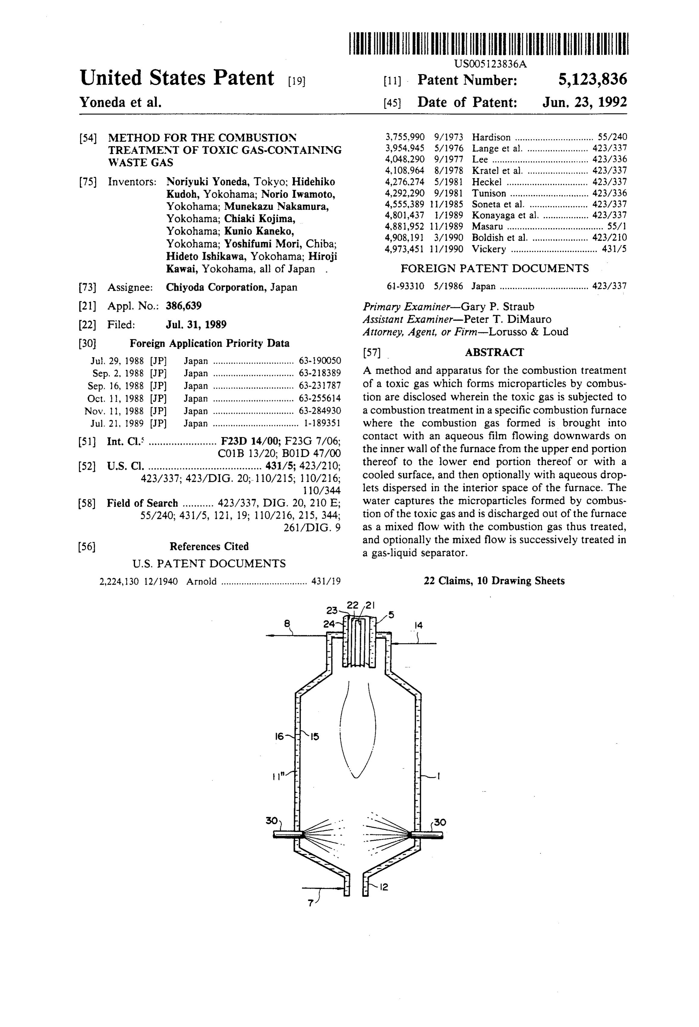
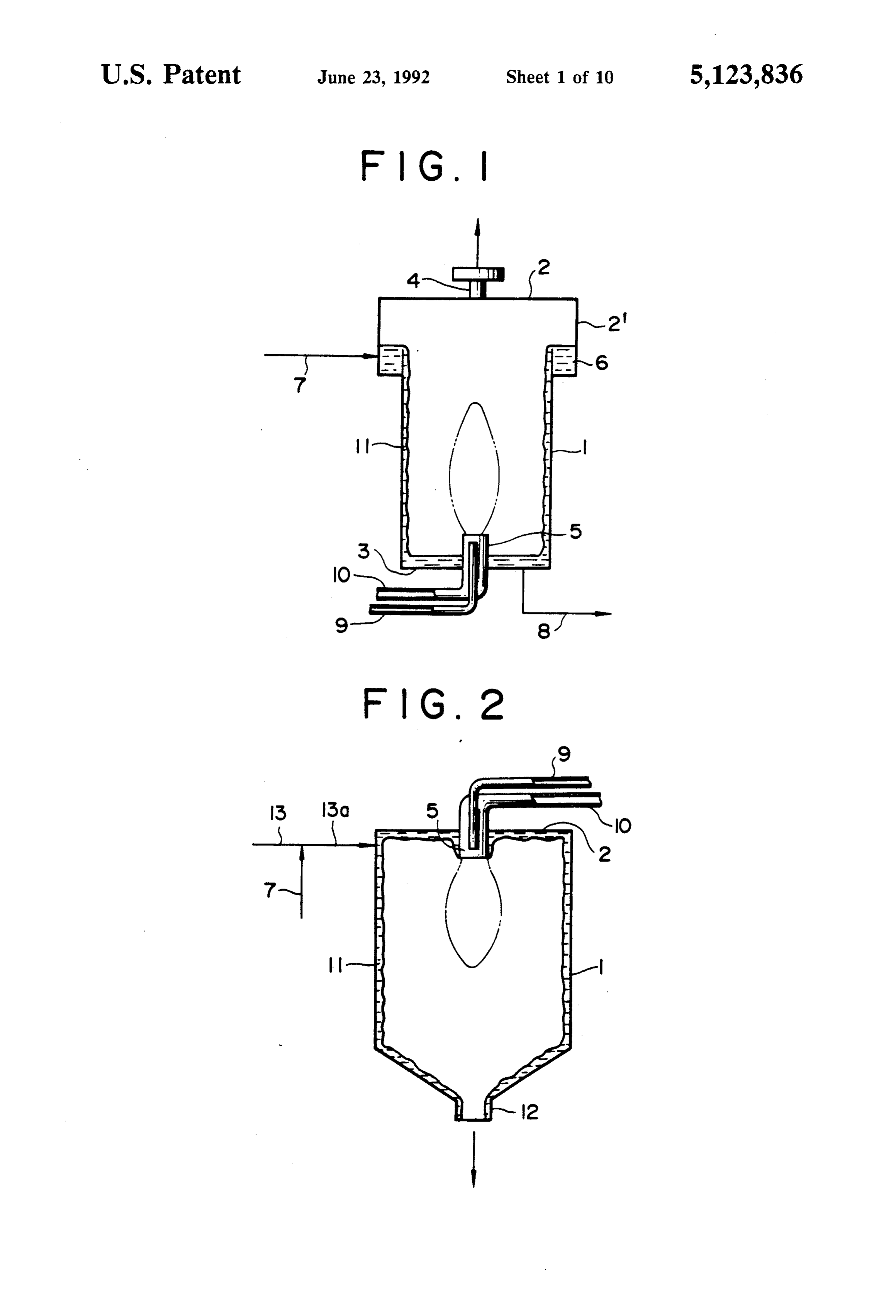
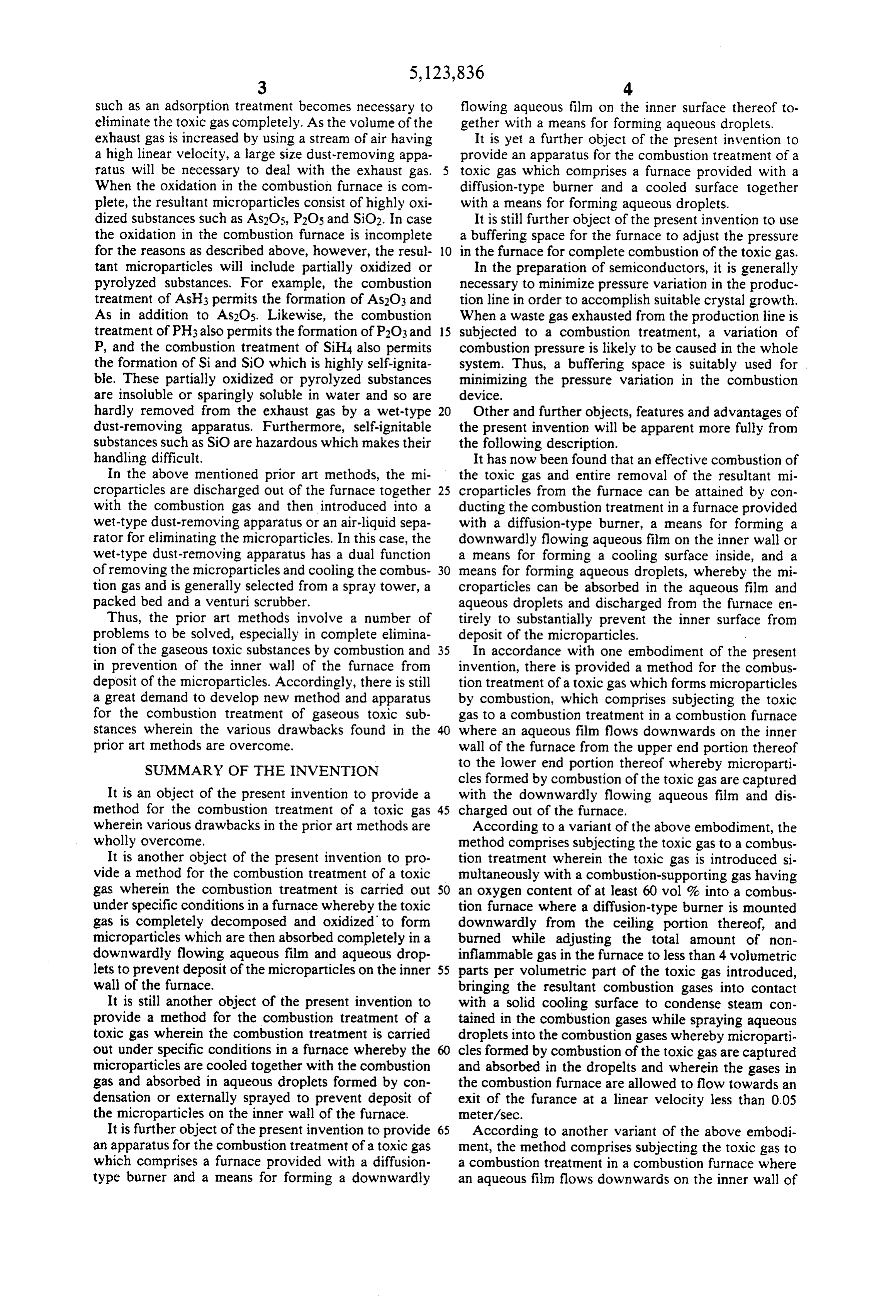
ing gas of a higher oxygen content serves to reduce the FIG. 1 is a longitudinal cross sectio of one example of amount of nitrogen in the combustion gas so that the the apparatus of this invention wherein a combustion total volume of the combustion gas discharged out of 25 burner is mounted to extend upwardly from the bottom the combustion furnace can effectively be reduced to of the combustion furnace.
make the subsequent after-treatment advantageous. FIG. 2 is a longitudinal cross section of a similar When the gasesous toxic substance is subjected to a example of the apparatus of this invention wherein a combustion treatment, the substance is oxidatively de combustion burner extends from the ceiling portion of composed in gaseous phase to form solid microparticles. 30 the combustion furnace.
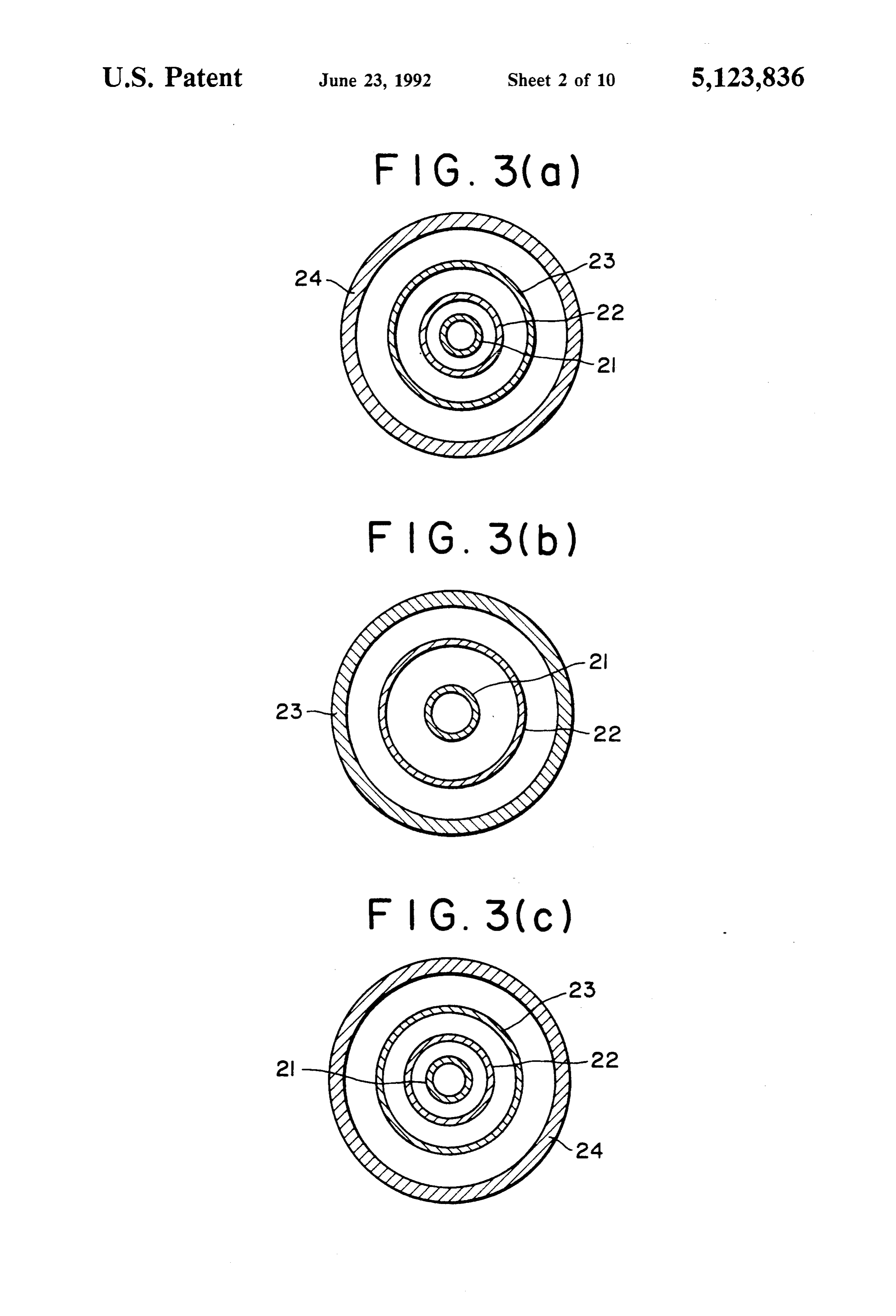
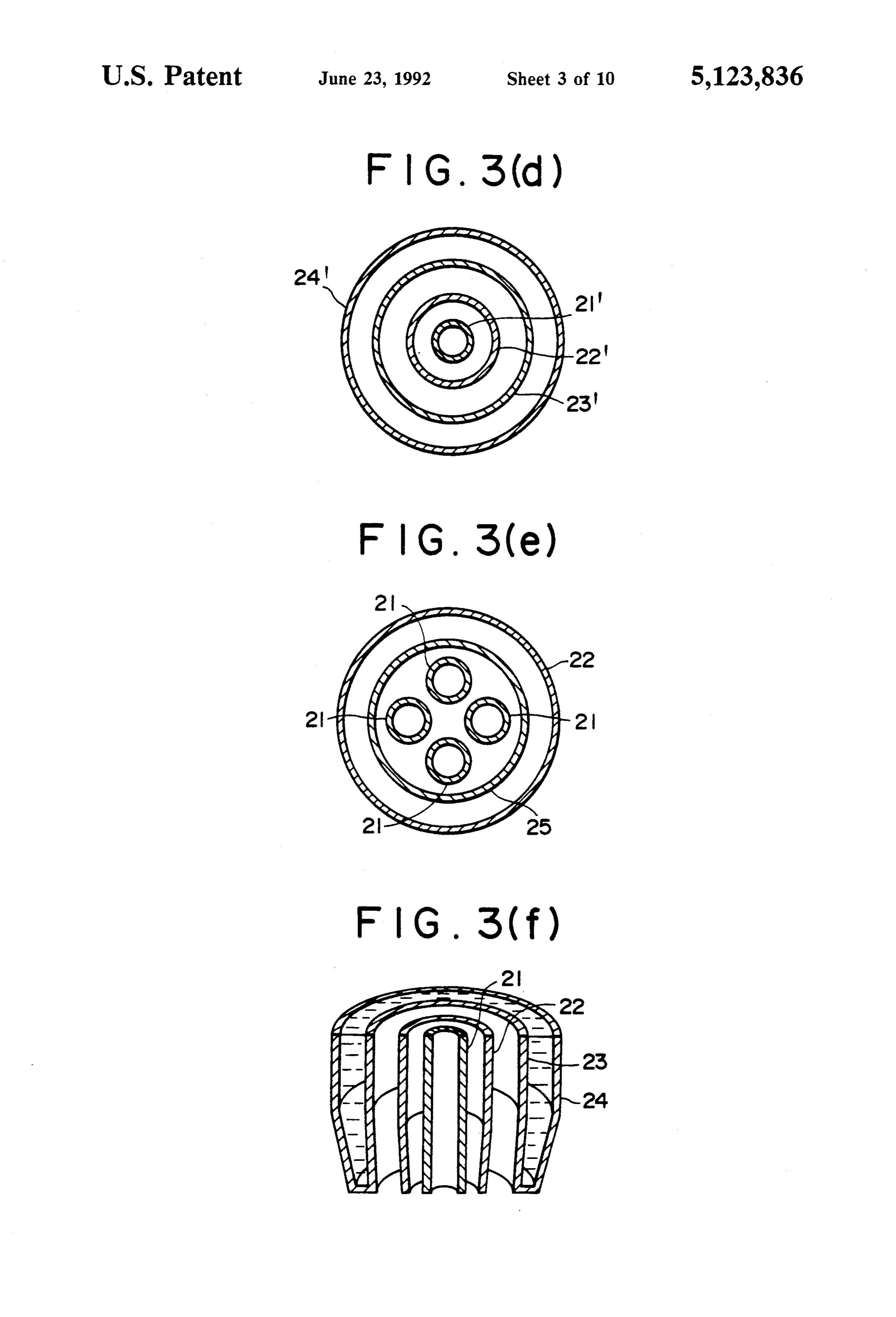
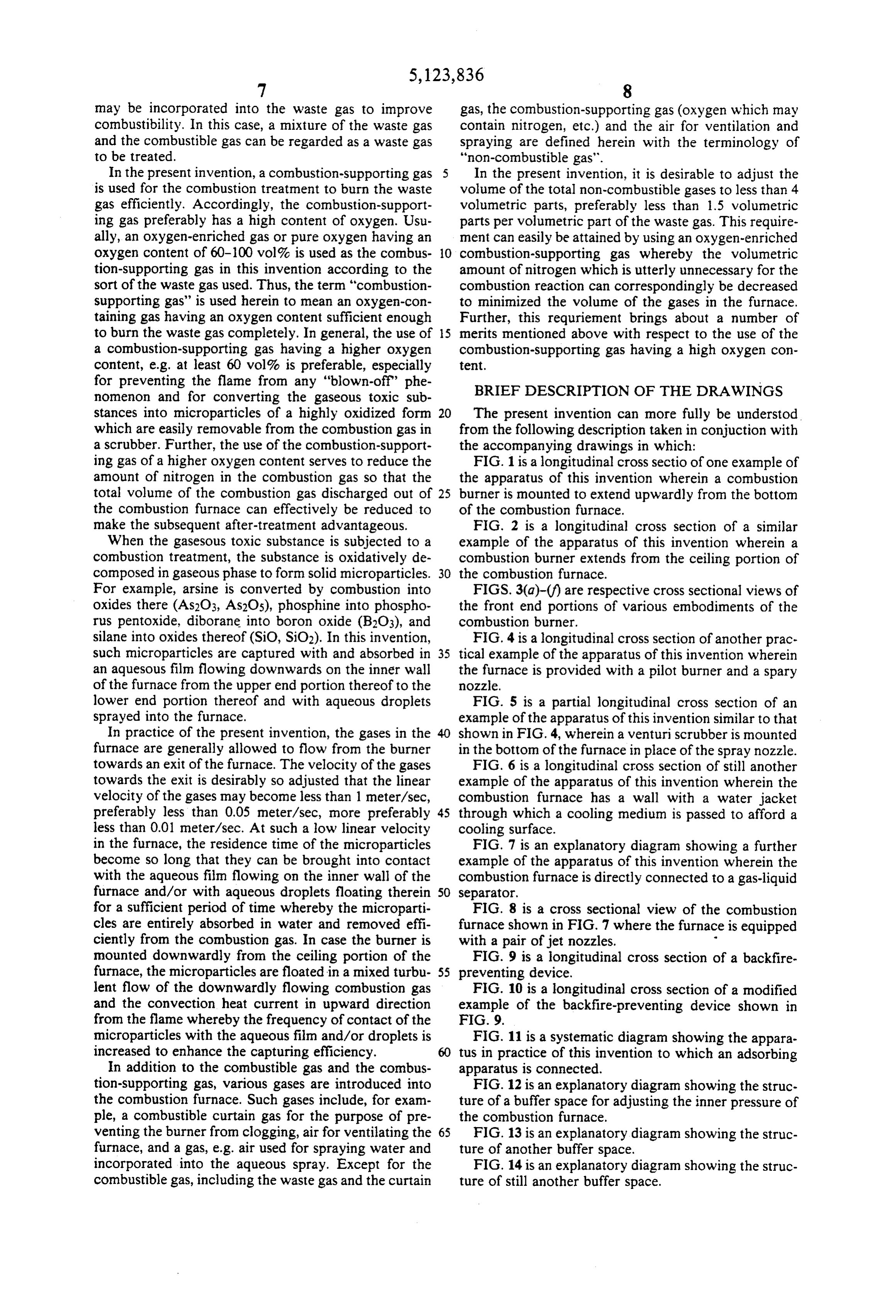
For example, arsine is converted by combustion into FIGS. 3(a)-(f) are respective cross sectional views of oxides there (As2O3, As2O5), phosphine into phospho the front end portions of various embodiments of the rus pentoxide, diborane into boron oxide (B2O3), and combustion burner.
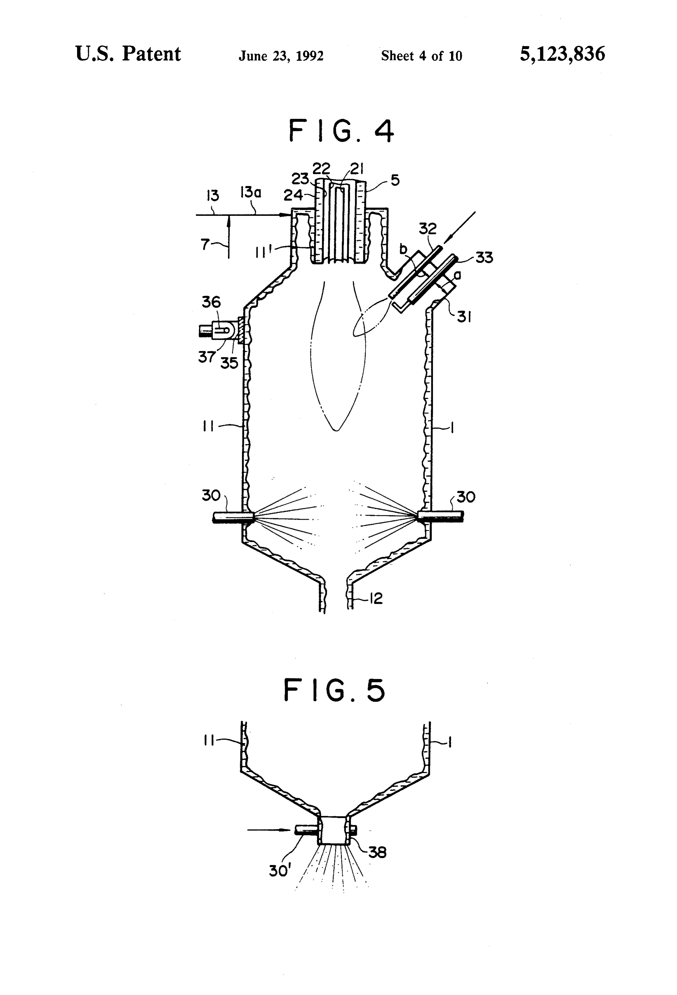
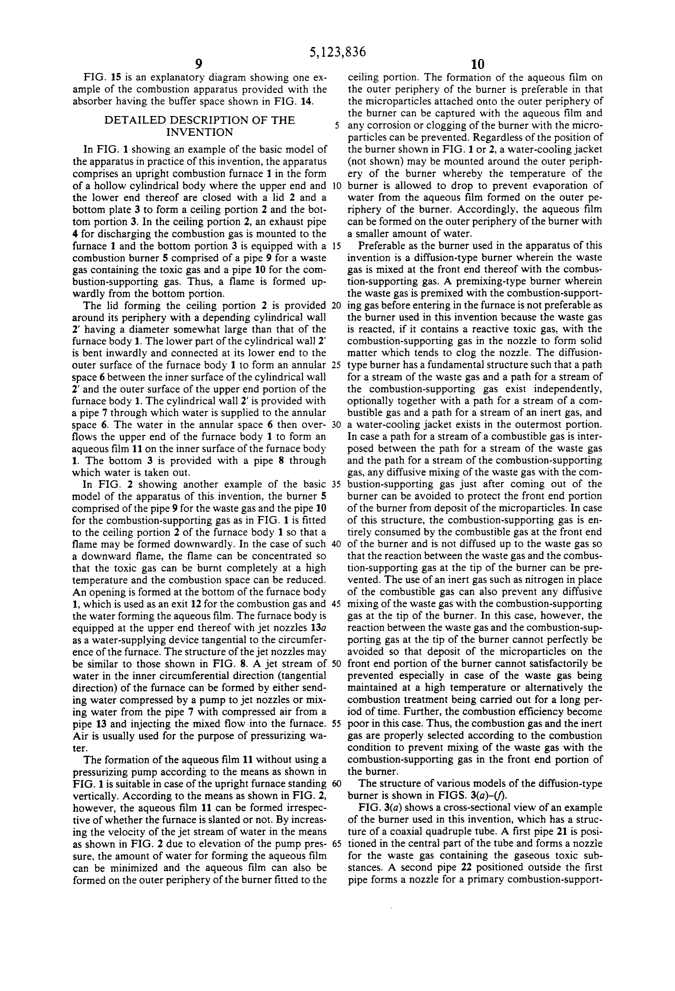
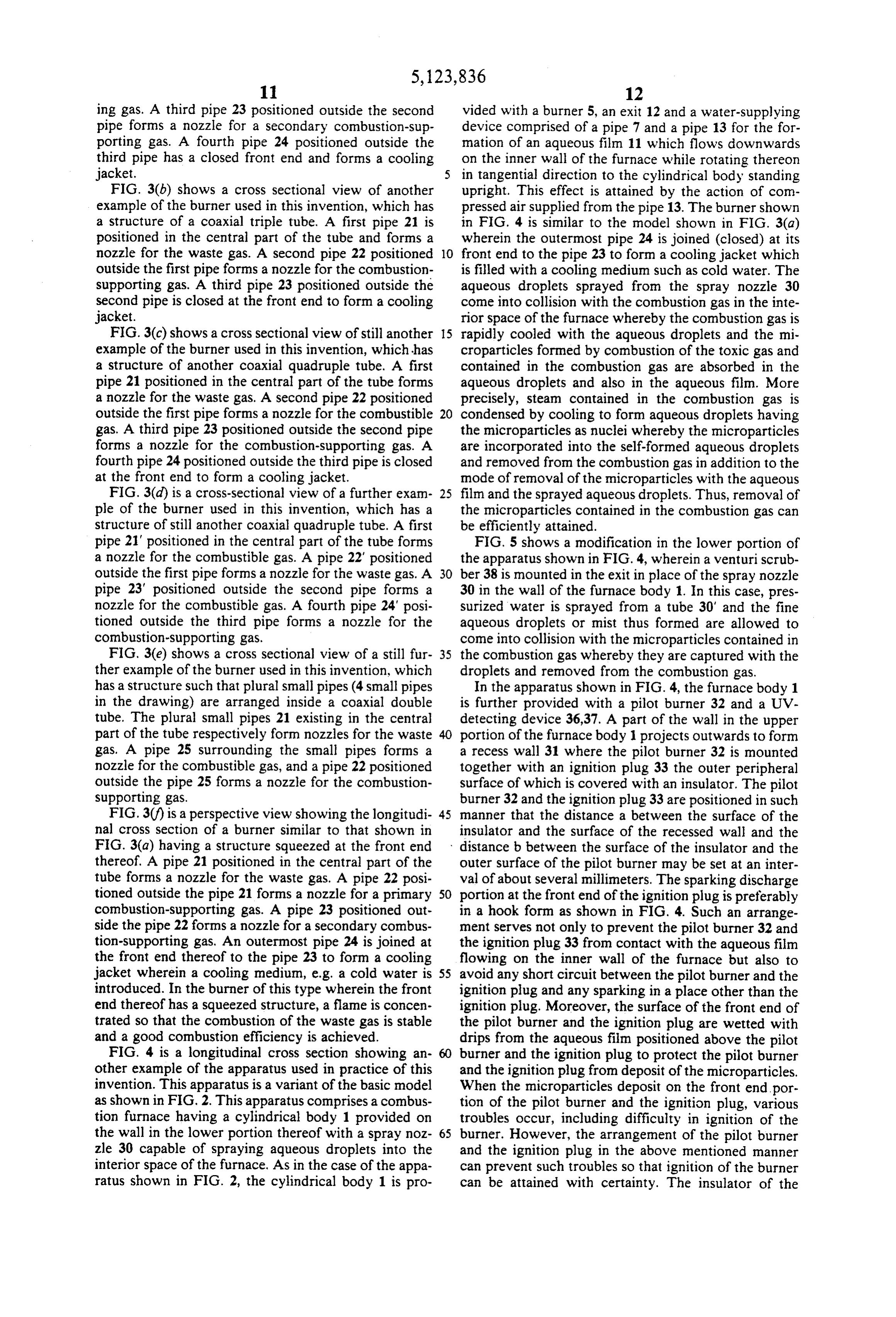
silane into oxides thereof (SiO, SiO2). In this invention, FIG. 4 is a longitudinal cross section of another prac such microparticles are captured with and absorbed in 35 tical example of the apparatus of this invention wherein an aquesous film flowing downwards on the inner wall the furnace is provided with a pilot burner and a spary of the furnace from the upper end portion thereof to the nozzle.
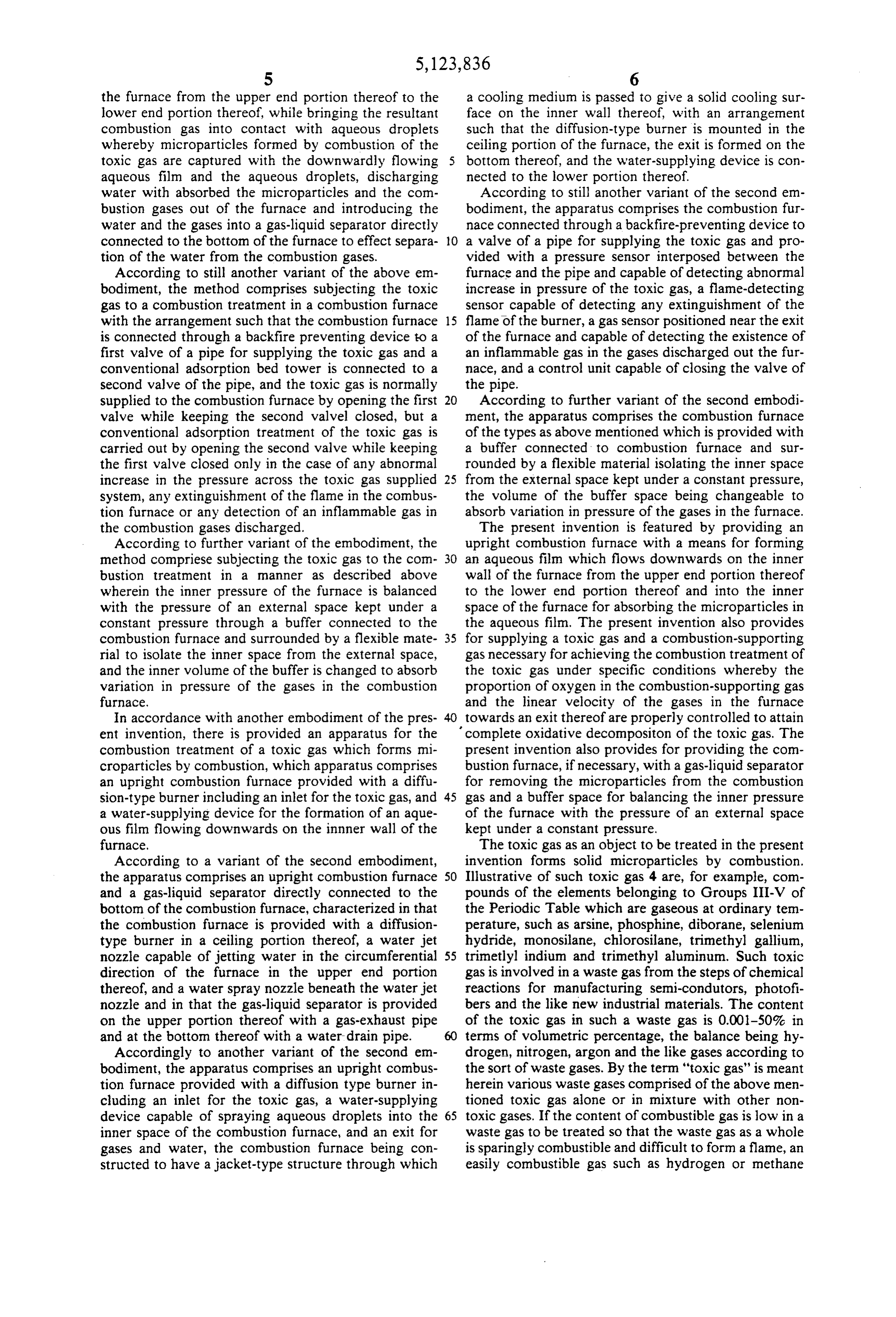
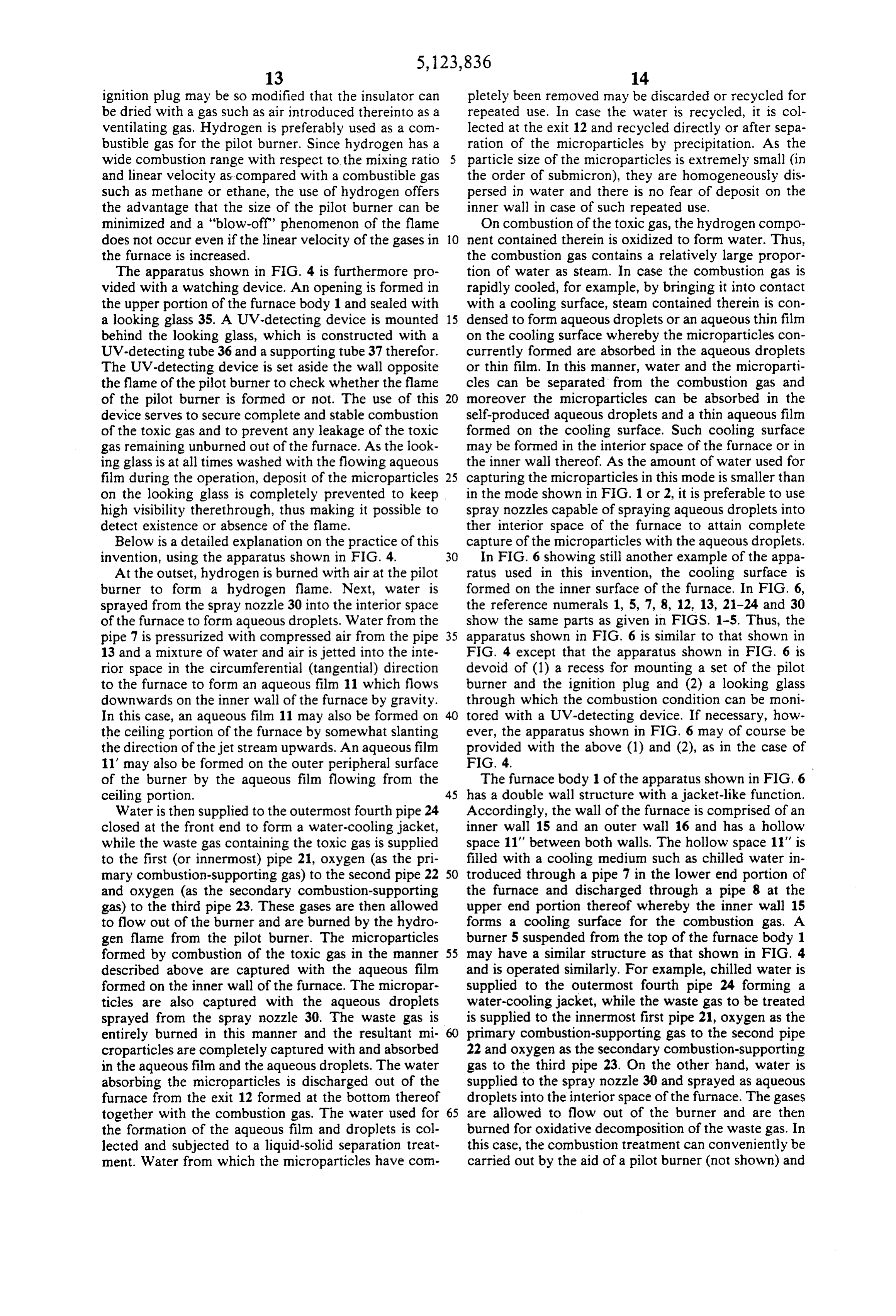
lower end portion thereof and with aqueous droplets FIG. 5 is a partial longitudinal cross section of an sprayed into the furnace. example of the apparatus of this invention similar to that In practice of the present invention, the gases in the shown in FIG. 4, wherein a venturi scrubber is mounted furnace are generally allowed to flow from the burner in the bottom of the furnace in place of the spray nozzle. towards an exit of the furnace. The velocity of the gases FIG. 6 is a longitudinal cross section of still another towards the exit is desirably so adjusted that the linear example of the apparatus of this invention wherein the velocity of the gases may become less than 1 meter/sec, combustion furnace has a wall with a water jacket preferably less than 0.05 meter/sec, more preferably 45 through which a cooling medium is passed to afford a less than 0.01 meter/sec. At such a low linear velocity cooling surface.
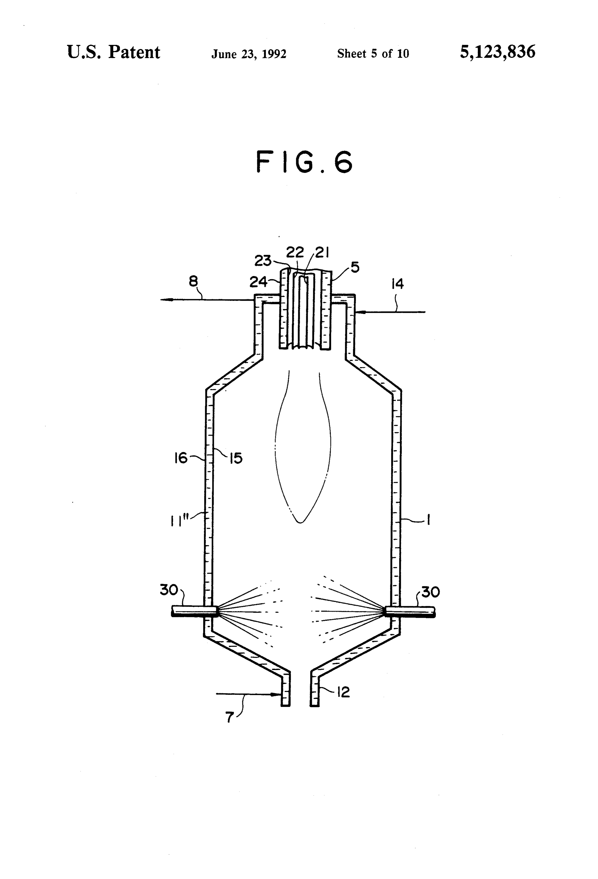
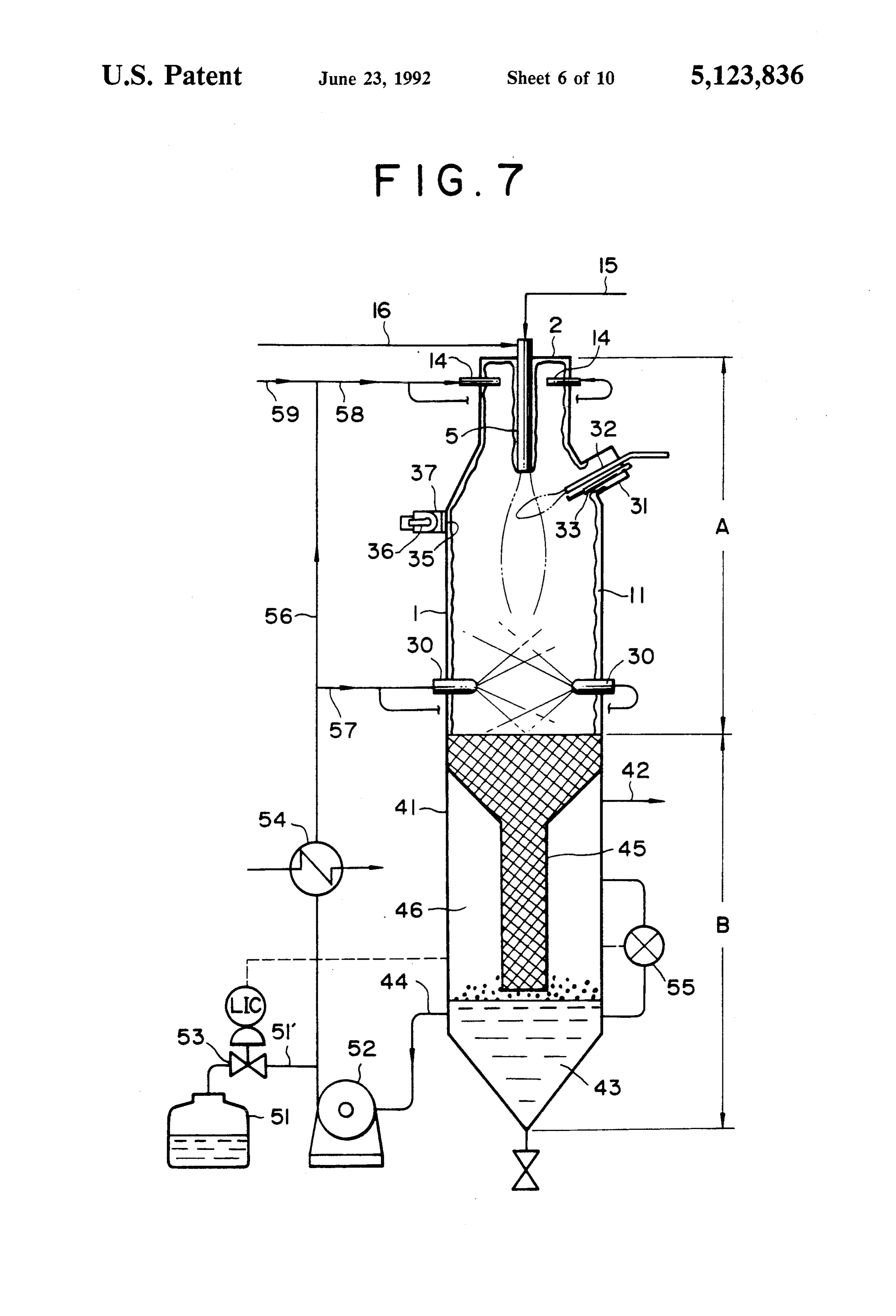
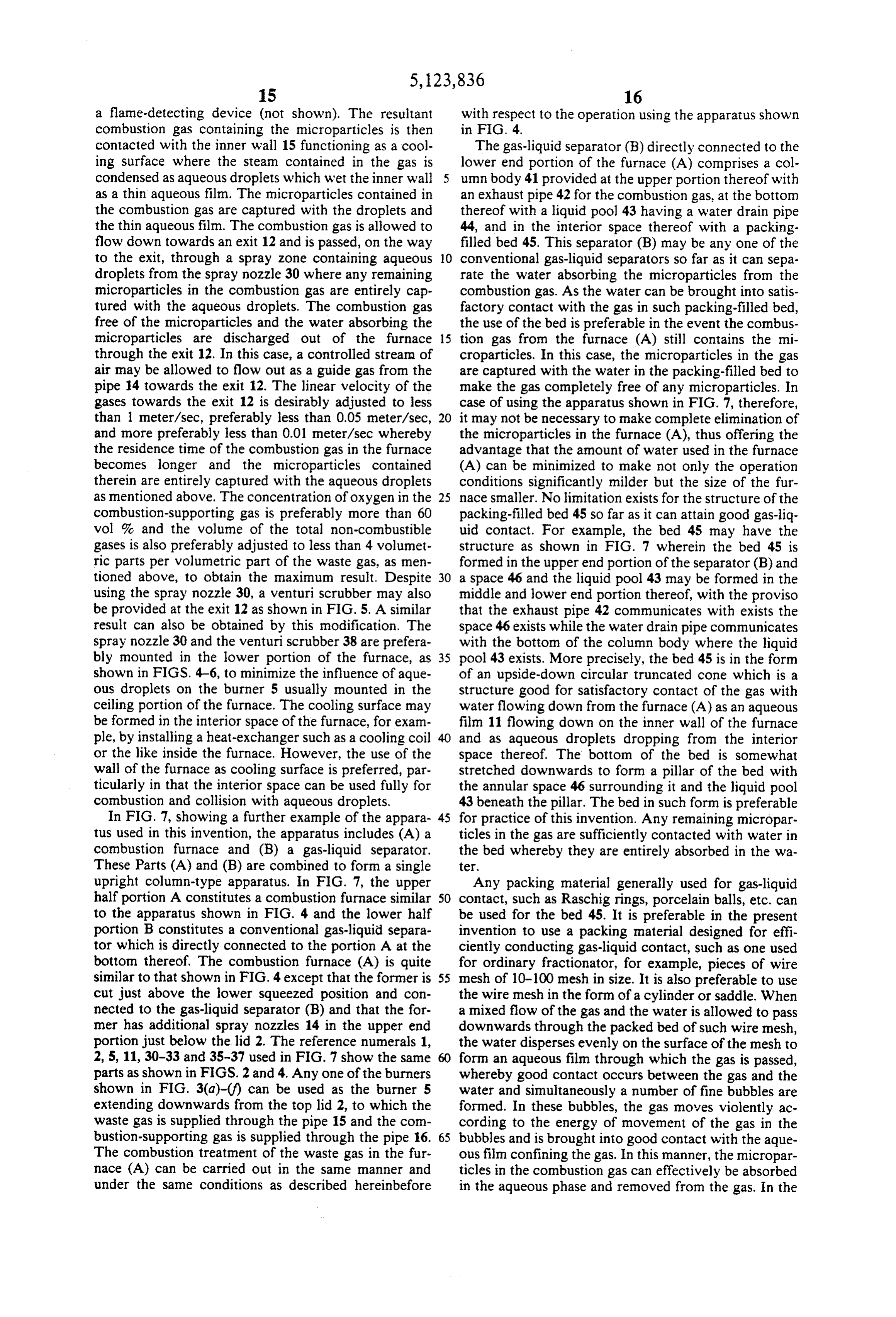
in the furnace, the residence time of the microparticles FIG. 7 is an explanatory diagram showing a further become so long that they can be brought into contact example of the apparatus of this invention wherein the with the aqueous film flowing on the inner wall of the combustion furnace is directly connected to a gas-liquid furnace and/or with aqueous droplets floating therein 50 separator.
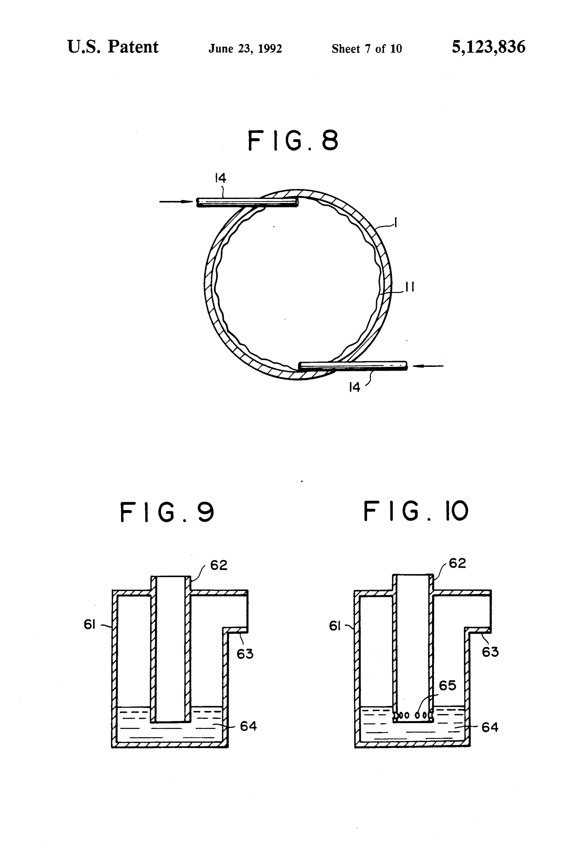
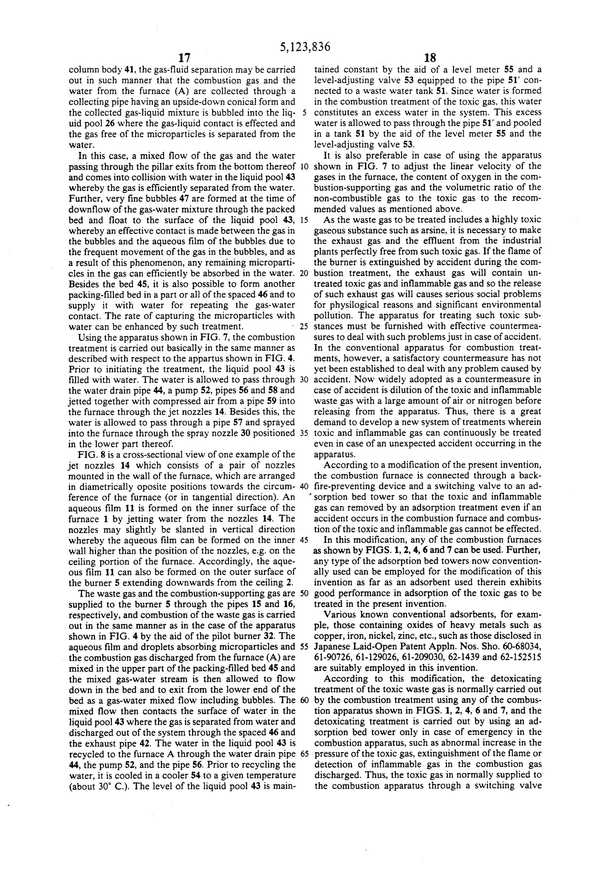
for a sufficient period of time whereby the microparti FIG. 8 is a cross sectional view of the combustion cles are entirely absorbed in water and removed effi furnace shown in FIG. 7 where the furnace is equipped ciently from the combustion gas. In case the burner is with a pair of jet nozzles.
mounted downwardly from the ceiling portion of the FIG. 9 is a longitudinal cross section of a backfire furnace, the microparticles are floated in a mixed turbu 55 preventing device.
lent flow of the downwardly flowing combustion gas FIG. 10 is a longitudinal cross section of a modified and the convection heat current in upward direction example of the backfire-preventing device shown in from the flame whereby the frequency of contact of the FIG. 9.
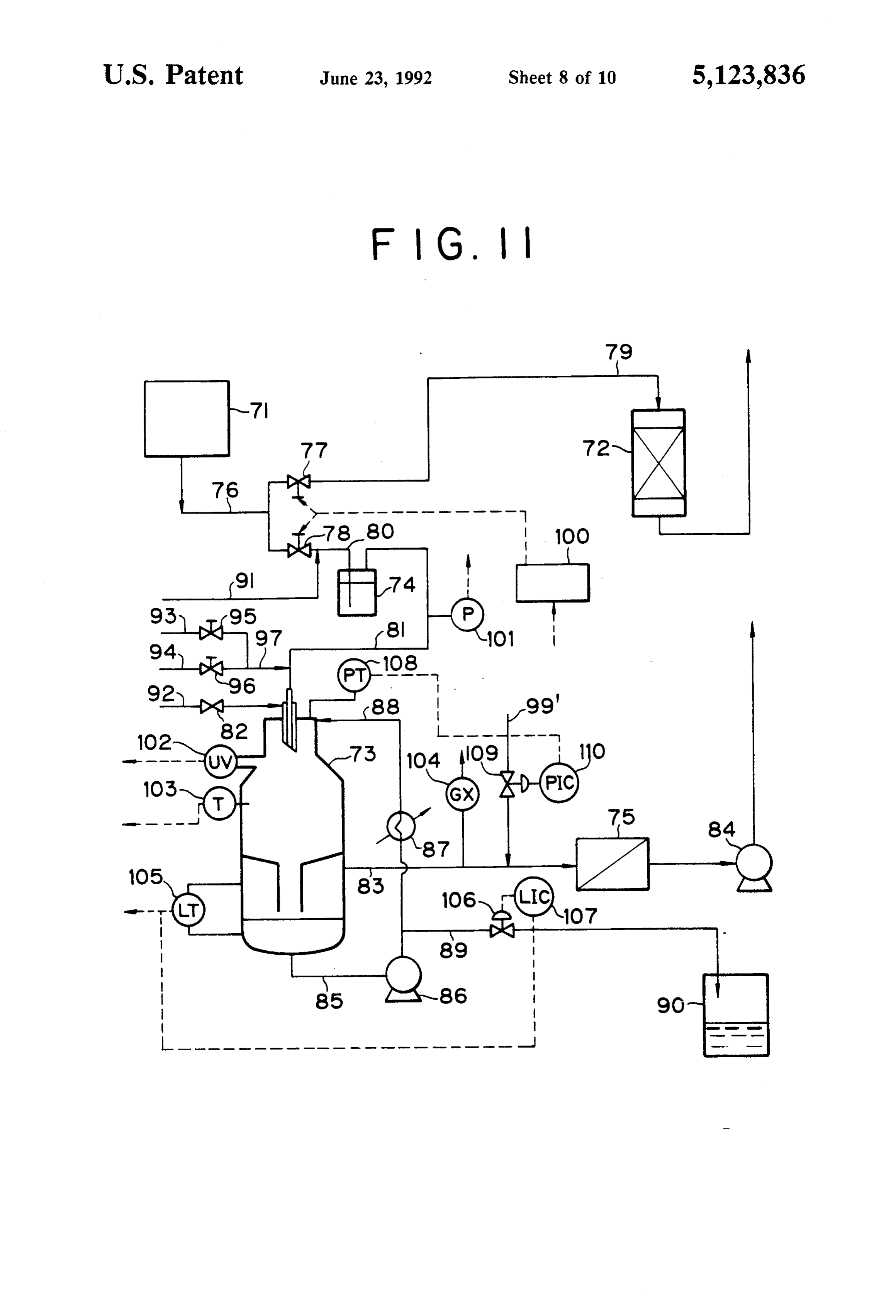
microparticles with the aqueous film and/or droplets is FIG. 11 is a systematic diagram showing the appara increased to enhance the capturing efficiency. tus in practice of this invention to which an adsorbing In addition to the combustible gas and the combus apparatus is connected.
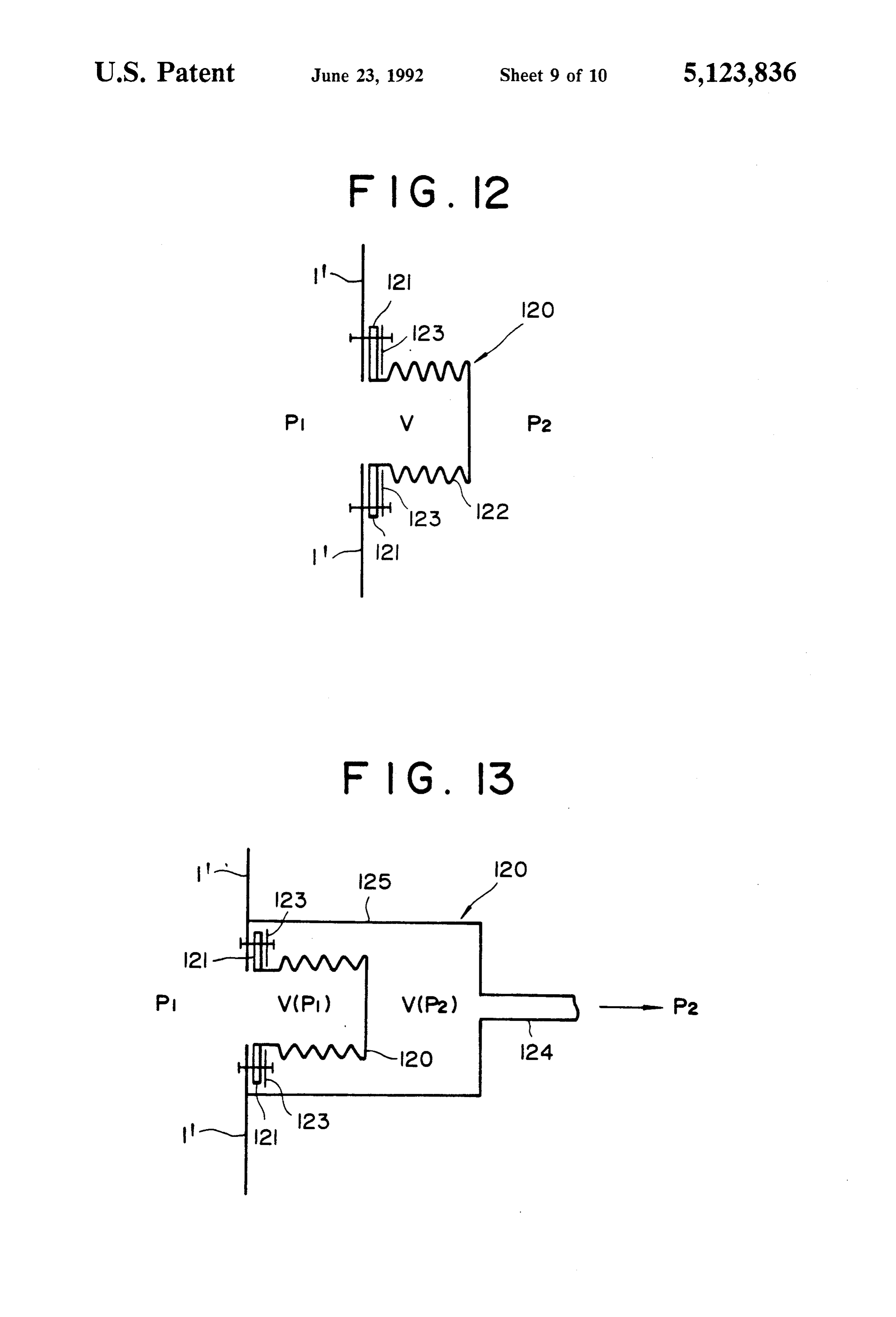
tion-supporting gas, various gases are introduced into FIG. 12 is an explanatory diagram showing the struc the combustion furnace. Such gases include, for exam ture of a buffer space for adjusting the inner pressure of ple, a combustible curtain gas for the purpose of pre the combustion furnace.
venting the burner from clogging, air for ventilating the 65 FIG. 13 is an explanatory diagram showing the struc furnace, and a gas, e.g. air used for spraying water and ture of another buffer space.
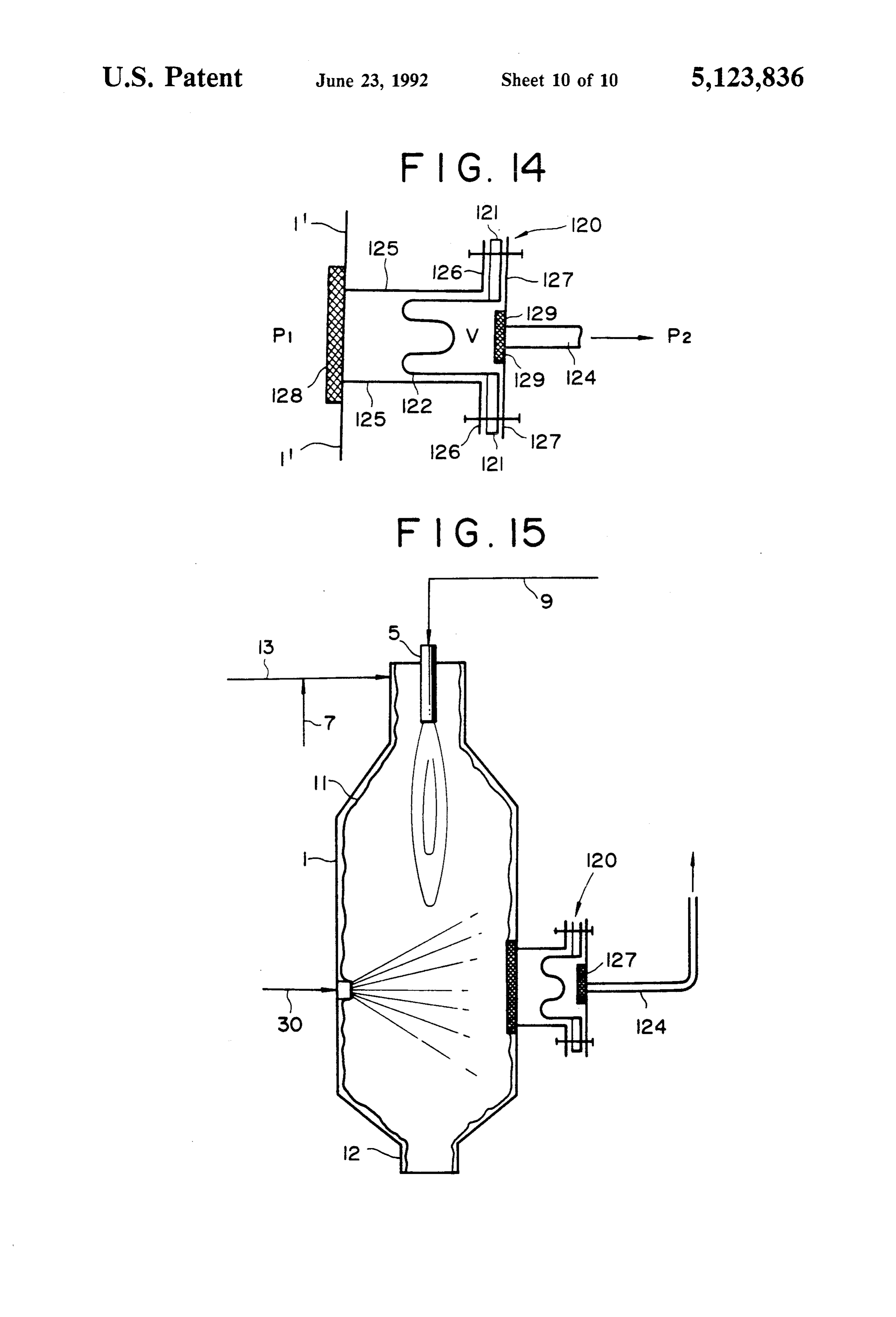
incorporated into the aqueous spray. Except for the FIG. 14 is an explanatory diagram showing the struc combustible gas, including the waste gas and the curtain ture of still another buffer space.
Page 16
FIG. 15 is an explanatory diagram showing one ex ceiling portion. The formation of the aqueous film on ample of the combustion apparatus provided with the the outer periphery of the burner is preferable in that absorber having the buffer space shown in FIG. 14. the microparticles attached onto the outer periphery of DETAILED DESCRIPTION OF THE the burner can be captured with the aqueous film and INVENTION any corrosion or clogging of the burner with the micro particles can be prevented. Regardless of the position of
In FIG. 1 showing an example of the basic model of the burner shown in FIG. 1 or 2, a water-cooling jacket the apparatus in practice of this invention, the apparatus (not shown) may be mounted around the outer periph comprises an upright combustion furnace 1 in the form ery of the burner whereby the temperature of the of a hollow cylindrical body where the upper end and O burner is allowed to drop to prevent evaporation of the lower end thereof are closed with a lid 2 and a water from the aqueous film formed on the outer pe bottom plate 3 to form a ceiling portion 2 and the bot riphery of the burner. Accordingly, the aqueous film tom portion 3. In the ceiling portion 2, an exhaust pipe can be formed on the outer periphery of the burner with 4 for discharging the combustion gas is mounted to the a smaller amount of water.
furnace 1 and the bottom portion 3 is equipped with a 15 Preferable as the burner used in the apparatus of this combustion burner 5 comprised of a pipe 9 for a waste invention is a diffusion-type burner wherein the waste gas containing the toxic gas and a pipe 10 for the com gas is mixed at the front end thereof with the combus bustion-supporting gas. Thus, a flame is formed up tion-supporting gas. A premixing-type burner wherein wardly from the bottom portion. the waste gas is premixed with the combustion-support The lid forming the ceiling portion 2 is provided ing gas before entering in the furnace is not preferable as around its periphery with a depending cylindrical wall the burner used in this invention because the waste gas 2' having a diameter somewhat large than that of the is reacted, if it contains a reactive toxic gas, with the furnace body 1. The lower part of the cylindrical wall 2" combustion-supporting gas in the nozzle to form solid is bent inwardly and connected at its lower end to the matter which tends to clog the nozzle. The diffusion outer surface of the furnace body 1 to form an annular 25 type burner has a fundamental structure such that a path space 6 between the inner surface of the cylindrical wall for a stream of the waste gas and a path for a stream of 2" and the outer surface of the upper end portion of the the combustion-supporting gas exist independently, furnace body . The cylindrical wall 2' is provided with optionally together with a path for a stream of a com a pipe 7 through which water is supplied to the annular bustible gas and a path for a stream of an inert gas, and space 6. The water in the annular space 6 then over 30 a water-cooling jacket exists in the outermost portion. flows the upper end of the furnace body 1 to form an In case a path for a stream of a combustible gas is inter aqueous film 11 on the inner surface of the furnace body posed between the path for a stream of the waste gas 1. The bottom 3 is provided with a pipe 8 through and the path for a stream of the combustion-supporting which water is taken out. gas, any diffusive mixing of the waste gas with the com In FIG. 2 showing another example of the basic 35 bustion-supporting gas just after coming out of the model of the apparatus of this invention, the burner 5 burner can be avoided to protect the front end portion comprised of the pipe 9 for the waste gas and the pipe 10 of the burner from deposit of the microparticles. In case for the combustion-supporting gas as in FIG. 1 is fitted of this structure, the combustion-supporting gas is en to the ceiling portion 2 of the furnace body 1 so that a tirely consumed by the combustible gas at the front end flame may be formed downwardly. In the case of such 40 of the burner and is not diffused up to the waste gas so a downward flame, the flame can be concentrated so that the reaction between the waste gas and the combus that the toxic gas can be burnt completely at a high tion-supporting gas at the tip of the burner can be pre temperature and the combustion space can be reduced. vented. The use of an inert gas such as nitrogen in place An opening is formed at the bottom of the furnace body of the combustible gas can also prevent any diffusive 1, which is used as an exit 12 for the combustion gas and 45 mixing of the waste gas with the combustion-supporting the water forming the aqueous film. The furnace body is gas at the tip of the burner. In this case, however, the equipped at the upper end thereof with jet nozzles 13a reaction between the waste gas and the combustion-sup as a water-supplying device tangential to the circumfer porting gas at the tip of the burner cannot perfectly be ence of the furnace. The structure of the jet nozzles may avoided so that deposit of the microparticles on the be similar to those shown in FIG. 8. A jet stream of 50 front end portion of the burner cannot satisfactorily be water in the inner circumferential direction (tangential prevented especially in case of the waste gas being direction) of the furnace can be formed by either send maintained at a high temperature or alternatively the ing water compressed by a pump to jet nozzles or mix combustion treatment being carried out for a long per ing water from the pipe 7 with compressed air from a iod of time. Further, the combustion efficiency become pipe 13 and injecting the mixed flow into the furnace. 55 poor in this case. Thus, the combustion gas and the inert Air is usually used for the purpose of pressurizing wa gas are properly selected according to the combustion te. condition to prevent mixing of the waste gas with the The formation of the aqueous film 11 without using a combustion-supporting gas in the front end portion of pressurizing pump according to the means as shown in the burner.
FIG. 1 is suitable in case of the upright furnace standing The structure of various models of the diffusion-type vertically. According to the means as shown in FIG. 2, burner is shown in FIGS. 3(a)-(f). however, the aqueous film 11 can be formed irrespec FIG.3(a) shows a cross-sectional view of an example tive of whether the furnace is slanted or not. By increas of the burner used in this invention, which has a struc ing the velocity of the jet stream of water in the means ture of a coaxial quadruple tube. A first pipe 21 is posi as shown in FIG. 2 due to elevation of the pump pres 65 tioned in the central part of the tube and forms a nozzie sure, the amount of water for forming the aqueous film for the waste gas containing the gaseous toxic sub can be minimized and the aqueous film can also be stances. A second pipe 22 positioned outside the first formed on the outer periphery of the burner fitted to the pipe forms a nozzle for a primary combustion-support
Page 17
ing gas. A third pipe 23 positioned outside the second vided with a burner 5, an exit 12 and a water-supplying pipe forms a nozzle for a secondary combustion-sup device comprised of a pipe 7 and a pipe 13 for the for porting gas. A fourth pipe 24 positioned outside the mation of an aqueous film 11 which flows downwards third pipe has a closed front end and forms a cooling on the inner wall of the furnace while rotating thereon jacket. in tangential direction to the cylindrical body standing FIG. 3(b) shows a cross sectional view of another upright. This effect is attained by the action of com example of the burner used in this invention, which has pressed air supplied from the pipe 13. The burner shown a structure of a coaxial triple tube. A first pipe 21 is in FIG. 4 is similar to the model shown in FIG. 3(a) positioned in the central part of the tube and forms a wherein the outermost pipe 24 is joined (closed) at its nozzle for the waste gas. A second pipe 22 positioned 10 front end to the pipe 23 to form a cooling jacket which outside the first pipe forms a nozzle for the combustion is filled with a cooling medium such as cold water. The supporting gas. A third pipe 23 positioned outside the aqueous droplets sprayed from the spray nozzle 30 second pipe is closed at the front end to form a cooling come into collision with the combustion gas in the inte jacket. rior space of the furnace whereby the combustion gas is FIG. 3(c) shows a cross sectional view of still another 15 rapidly cooled with the aqueous droplets and the mi example of the burner used in this invention, which has croparticles formed by combustion of the toxic gas and a structure of another coaxial quadruple tube. A first contained in the combustion gas are absorbed in the pipe 21 positioned in the central part of the tube forms aqueous droplets and also in the aqueous film. More a nozzle for the waste gas. A second pipe 22 positioned precisely, steam contained in the combustion gas is outside the first pipe forms a nozzle for the combustible condensed by cooling to form aqueous droplets having gas. A third pipe 23 positioned outside the second pipe the microparticles as nuclei whereby the microparticles forms a nozzle for the combustion-supporting gas. A are incorporated into the self-formed aqueous droplets fourth pipe 24 positioned outside the third pipe is closed and removed from the combustion gas in addition to the at the front end to form a cooling jacket. mode of removal of the microparticles with the aqueous FIG. 3(d) is a cross-sectional view of a further exam 25 film and the sprayed aqueous droplets. Thus, removal of ple of the burner used in this invention, which has a the microparticles contained in the combustion gas can structure of still another coaxial quadruple tube. A first be efficiently attained.
pipe 21' positioned in the central part of the tube forms FIG. 5 shows a modification in the lower portion of a nozzle for the combustible gas. A pipe 22 positioned the apparatus shown in FIG.4, wherein a venturi scrub outside the first pipe forms a nozzle for the waste gas. A 30 ber 38 is mounted in the exit in place of the spray nozzle pipe 23' positioned outside the second pipe forms a 30 in the wall of the furnace body 1. In this case, pres nozzle for the combustible gas. A fourth pipe 24' posi surized water is sprayed from a tube 30' and the fine tioned outside the third pipe forms a nozzle for the aqueous droplets or mist thus formed are allowed to combustion-supporting gas. come into collision with the microparticles contained in FIG, 3(e) shows a cross sectional view of a still fur 35 the combustion gas whereby they are captured with the ther example of the burner used in this invention, which droplets and removed from the combustion gas. has a structure such that plural small pipes (4 small pipes In the apparatus shown in FIG. 4, the furnace body 1 in the drawing) are arranged inside a coaxial double is further provided with a pilot burner 32 and a UV tube. The plural small pipes 21 existing in the central detecting device 36,37. A part of the wall in the upper part of the tube respectively form nozzles for the waste portion of the furnace body 1 projects outwards to form gas. A pipe 25 surrounding the small pipes forms a a recess wall 31 where the pilot burner 32 is mounted nozzle for the combustible gas, and a pipe 22 positioned together with an ignition plug 33 the outer peripheral outside the pipe 25 forms a nozzle for the combustion surface of which is covered with an insulator. The pilot Supporting gas. burner 32 and the ignition plug 33 are positioned in such FIG. 3(f) is a perspective view showing the longitudi 45 manner that the distance a between the surface of the nal cross section of a burner similar to that shown in insulator and the surface of the recessed wall and the FIG. 3(a) having a structuresqueezed at the front end distance b between the surface of the insulator and the thereof. A pipe 21 positioned in the central part of the outer surface of the pilot burner may be set at an inter tube forms a nozzle for the waste gas. A pipe 22 posi val of about several millimeters. The sparking discharge tioned outside the pipe 21 forms a nozzle for a primary 50 portion at the front end of the ignition plug is preferably combustion-supporting gas. A pipe 23 positioned out in a hook form as shown in FIG. 4. Such an arrange side the pipe 22 forms a nozzle for a secondary combus ment serves not only to prevent the pilot burner 32 and tion-supporting gas. An outermost pipe 24 is joined at the ignition plug 33 from contact with the aqueous film the front end thereof to the pipe 23 to form a cooling flowing on the inner wall of the furnace but also to jacket wherein a cooling medium, e.g. a cold water is 55 avoid any short circuit between the pilot burner and the introduced. In the burner of this type wherein the front ignition plug and any sparking in a place other than the end thereof has a squeezed structure, a flame is concen ignition plug. Moreover, the surface of the front end of trated so that the combustion of the waste gas is stable the pilot burner and the ignition plug are wetted with and a good combustion efficiency is achieved. drips from the aqueous film positioned above the pilot FIG. 4 is a longitudinal cross section showing an burner and the ignition plug to protect the pilot burner other example of the apparatus used in practice of this and the ignition plug from deposit of the microparticles. invention. This apparatus is a variant of the basic model When the microparticles deposit on the front endpor as shown in FIG. 2. This apparatus comprises a combus tion of the pilot burner and the ignition plug, various tion furnace having a cylindrical body 1 provided on troubles occur, including difficulty in ignition of the the wall in the lower portion thereof with a spray noz 65 burner. However, the arrangement of the pilot burner zle 30 capable of spraying aqueous droplets into the and the ignition plug in the above mentioned manner interior space of the furnace. As in the case of the appa can prevent such troubles so that ignition of the burner ratus shown in FIG. 2, the cylindrical body 1 is pro can be attained with certainty. The insulator of the
Page 18
ignition plug may be so modified that the insulator can pletely been removed may be discarded or recycled for be dried with a gas such as air introduced thereinto as a repeated use. In case the water is recycled, it is co ventilating gas. Hydrogen is preferably used as a con lected at the exit 12 and recycled directly or after sepa bustible gas for the pilot burner. Since hydrogen has a ration of the microparticles by precipitation. As the wide combustion range with respect to the mixing ratio particle size of the microparticles is extremely small (in and linear velocity as compared with a combustible gas the order of submicron), they are homogeneously dis such as methane or ethane, the use of hydrogen offers persed in water and there is no fear of deposit on the the advantage that the size of the pilot burner can be inner wall in case of such repeated use. minimized and a "blow-off" phenomenon of the flame On combustion of the toxic gas, the hydrogen compo does not occur even if the linear velocity of the gases in 10 nent contained therein is oxidized to form water. Thus, the furnace is increased. the combustion gas contains a relatively large propor The apparatus shown in FIG. 4 is furthermore pro tion of water as steam. In case the combustion gas is vided with a watching device. An opening is formed in rapidly cooled, for example, by bringing it into contact the upper portion of the furnace body 1 and sealed with with a cooling surface, steam contained therein is con a looking glass 35. A UV-detecting device is mounted 15 densed to form aqueous droplets or an aqueous thin film behind the looking glass, which is constructed with a on the cooling surface whereby the microparticles con UV-detecting tube 36 and a supporting tube 37 therefor. currently formed are absorbed in the aqueous droplets The UV-detecting device is set aside the wall opposite or thin film. In this manner, water and the microparti the flame of the pilot burner to check whether the flame cles can be separated from the combustion gas and of the pilot burner is formed or not. The use of this 20 moreover the microparticles can be absorbed in the device serves to secure complete and stable combustion self-produced aqueous droplets and a thin aqueous film of the toxic gas and to prevent any leakage of the toxic formed on the cooling surface. Such cooling surface gas remaining unburned out of the furnace. As the look may be formed in the interior space of the furnace or in ing glass is at all times washed with the flowing aqueous the inner wall thereof. As the amount of water used for film during the operation, deposit of the microparticles 25 capturing the microparticles in this mode is smaller than on the looking glass is completely prevented to keep in the mode shown in FIG. 1 or 2, it is preferable to use high visibility therethrough, thus making it possible to spray nozzles capable of spraying aqueous droplets into detect existence or absence of the flame. ther interior space of the furnace to attain complete Below is a detailed explanation on the practice of this capture of the microparticles with the aqueous droplets. invention, using the apparatus shown in FIG. 4. 30 In FIG. 6 showing still another example of the appa At the outset, hydrogen is burned with air at the pilot ratus used in this invention, the cooling surface is burner to form a hydrogen flame. Next, water is formed on the inner surface of the furnace. In FIG. 6, sprayed from the spray nozzle 30 into the interior space the reference numerals 1, 5, 7, 8, 12, 13, 21-24 and 30 of the furnace to form aqueous droplets. Water from the show the same parts as given in FIGS. 1-5. Thus, the pipe 7 is pressurized with compressed air from the pipe 35 apparatus shown in FIG. 6 is similar to that shown in 13 and a mixture of water and air is jetted into the inte FIG. 4 except that the apparatus shown in FIG. 6 is rior space in the circumferential (tangential) direction devoid of (1) a recess for mounting a set of the pilot to the furnace to form an aqueous film 11 which flows burner and the ignition plug and (2) a looking glass downwards on the inner wall of the furnace by gravity. through which the combustion condition can be moni In this case, an aqueous film 11 may also be formed on tored with a UV-detecting device. If necessary, how the ceiling portion of the furnace by somewhat slanting ever, the apparatus shown in FIG. 6 may of course be the direction of the jet stream upwards. An aqueous film provided with the above (1) and (2), as in the case of 11' may also be formed on the outer peripheral surface FIG. 4. v of the burner by the aqueous film flowing from the The furnace body 1 of the apparatus shown in FIG. 6 ceiling portion. 45 has a double wall structure with a jacket-like function. Water is then supplied to the outermost fourth pipe 24 Accordingly, the wall of the furnace is comprised of an closed at the front end to form a water-cooling jacket, inner wall 15 and an outer wall 16 and has a hollow while the waste gas containing the toxic gas is supplied space 11" between both walls. The hollow space 11" is to the first (or innermost) pipe 21, oxygen (as the pri filled with a cooling medium such as chilled water in mary combustion-supporting gas) to the second pipe 22 SO troduced through a pipe 7 in the lower end portion of and oxygen (as the secondary combustion-supporting the furnace and discharged through a pipe 8 at the gas) to the third pipe 23. These gases are then allowed upper end portion thereof whereby the inner wall 15 to flow out of the burner and are burned by the hydro forms a cooling surface for the combustion gas. A gen flame from the pilot burner. The microparticles burner 5 suspended from the top of the furnace body 1 formed by combustion of the toxic gas in the manner 55 may have a similar structure as that shown in FIG. 4 described above are captured with the aqueous film and is operated similarly. For example, chilled water is formed on the inner wall of the furnace. The micropar supplied to the outermost fourth pipe 24 forming a ticles are also captured with the aqueous droplets water-cooling jacket, while the waste gas to be treated sprayed from the spray nozzle 30. The waste gas is is supplied to the innermost first pipe 21, oxygen as the entirely burned in this manner and the resultant mi primary combustion-supporting gas to the second pipe croparticles are completely captured with and absorbed 22 and oxygen as the secondary combustion-supporting in the aqueous film and the aqueous droplets. The water gas to the third pipe 23. On the other hand, water is absorbing the microparticles is discharged out of the supplied to the spray nozzle 30 and sprayed as aqueous furnace from the exit 12 formed at the bottom thereof droplets into the interior space of the furnace. The gases together with the combustion gas. The water used for 65 are allowed to flow out of the burner and are then the formation of the aqueous film and droplets is col burned for oxidative decomposition of the waste gas. In lected and subjected to a liquid-solid separation treat this case, the combustion treatment can conveniently be ment. Water from which the microparticles have com carried out by the aid of a pilot burner (not shown) and
Page 19
a flame-detecting device (not shown). The resultant with respect to the operation using the apparatus shown combustion gas containing the microparticles is then in FIG. 4.
contacted with the inner wall 15 functioning as a cool The gas-liquid separator (B) directly connected to the ing surface where the steam contained in the gas is lower end portion of the furnace (A) comprises a col condensed as aqueous droplets which wet the inner wall umn body 41 provided at the upper portion thereof with as a thin aqueous film. The microparticles contained in an exhaust pipe 42 for the combustion gas, at the bottom the combustion gas are captured with the droplets and thereof with a liquid pool 43 having a water drain pipe the thin aqueous film. The combustion gas is allowed to 44, and in the interior space thereof with a packing flow down towards an exit 12 and is passed, on the way filled bed 45. This separator (B) may be any one of the to the exit, through a spray zone containing aqueous O conventional gas-liquid separators so far as it can sepa droplets from the spray nozzle 30 where any remaining rate the water absorbing the microparticles from the microparticles in the combustion gas are entirely cap combustion gas. As the water can be brought into satis tured with the aqueous droplets. The combustion gas factory contact with the gas in such packing-filled bed, free of the microparticles and the water absorbing the the use of the bed is preferable in the event the combus microparticles are discharged out of the furnace 15 tion gas from the furnace (A) still contains the mi through the exit 12. In this case, a controlled stream of croparticles. In this case, the microparticles in the gas air may be allowed to flow out as a guide gas from the are captured with the water in the packing-filled bed to pipe 14 towards the exit 12. The linear velocity of the make the gas completely free of any microparticles. In gases towards the exit 12 is desirably adjusted to less case of using the apparatus shown in FIG. 7, therefore, than 1 meter/sec, preferably less than 0.05 meter/sec, it may not be necessary to make complete elimination of and more preferably less than 0.01 meter/sec whereby the microparticles in the furnace (A), thus offering the the residence time of the combustion gas in the furnace advantage that the amount of water used in the furnace becomes longer and the microparticles contained (A) can be minimized to make not only the operation therein are entirely captured with the aqueous droplets conditions significantly milder but the size of the fur as mentioned above. The concentration of oxygen in the 25 nace smaller. No limitation exists for the structure of the combustion-supporting gas is preferably more than 60 packing-filled bed 45 so far as it can attain good gas-liq vol % and the volume of the total non-combustible uid contact. For example, the bed 45 may have the gases is also preferably adjusted to less than 4 volumet structure as shown in FIG. 7 wherein the bed 45 is ric parts per volumetric part of the waste gas, as men formed in the upper end portion of the separator (B) and tioned above, to obtain the maximum result. Despite 30 a space 46 and the liquid pool 43 may be formed in the using the spray nozzle 30, a venturi scrubber may also middle and lower end portion thereof, with the proviso be provided at the exit 12 as shown in FIG. 5. A similar that the exhaust pipe 42 communicates with exists the result can also be obtained by this modification. The space 46 exists while the water drain pipe communicates spray nozzle 30 and the venturi scrubber 38 are prefera with the bottom of the column body where the liquid bly mounted in the lower portion of the furnace, as 35 pool 43 exists. More precisely, the bed 45 is in the form shown in FIGS. 4-6, to minimize the influence of aque of an upside-down circular truncated cone which is a ous droplets on the burner 5 usually mounted in the structure good for satisfactory contact of the gas with ceiling portion of the furnace. The cooling surface may water flowing down from the furnace (A) as an aqueous be formed in the interior space of the furnace, for exam film 11 flowing down on the inner wall of the furnace ple, by installing a heat-exchanger such as a cooling coil and as aqueous droplets dropping from the interior or the like inside the furnace. However, the use of the space thereof. The bottom of the bed is somewhat wall of the furnace as cooling surface is preferred, par stretched downwards to form a pillar of the bed with ticularly in that the interior space can be used fully for the annular space 46 surrounding it and the liquid pool combustion and collision with aqueous droplets. 43 beneath the pillar. The bed in such form is preferable In FIG. 7, showing a further example of the appara 45 for practice of this invention. Any remaining micropar tus used in this invention, the apparatus includes (A) a ticles in the gas are sufficiently contacted with water in combustion furnace and (B) a gas-liquid separator. the bed whereby they are entirely absorbed in the wa These Parts (A) and (B) are combined to form a single te?t.
upright column-type apparatus. In FIG. 7, the upper Any packing material generally used for gas-liquid half portion A constitutes a combustion furnace similar 50 contact, such as Raschig rings, porcelain balls, etc. can to the apparatus shown in FIG. 4 and the lower half be used for the bed 45. It is preferable in the present portion B constitutes a conventional gas-liquid separa invention to use a packing material designed for effi tor which is directly connected to the portion A at the ciently conducting gas-liquid contact, such as one used bottom thereof. The combustion furnace (A) is quite for ordinary fractionator, for example, pieces of wire similar to that shown in FIG. 4 except that the former is 55 mesh of 10-100 mesh in size. It is also preferable to use cut just above the lower squeezed position and con the wire mesh in the form of a cylinder or saddle. When nected to the gas-liquid separator (B) and that the for a mixed flow of the gas and the water is allowed to pass mer has additional spray nozzles 14 in the upper end downwards through the packed bed of such wire mesh, portion just below the lid 2. The reference numerals 1, the water disperses evenly on the surface of the mesh to 2, 5, 11, 30-33 and 35-37 used in FIG. 7 show the same form an aqueous film through which the gas is passed, parts as shown in FIGS. 2 and 4. Any one of the burners whereby good contact occurs between the gas and the shown in FIG. 3(a)-(f) can be used as the burner 5 water and simultaneously a number of fine bubbles are extending downwards from the top lid 2, to which the formed. In these bubbles, the gas moves violently ac waste gas is supplied through the pipe 15 and the com cording to the energy of movement of the gas in the bustion-supporting gas is supplied through the pipe 16. 65 bubbles and is brought into good contact with the aque The combustion treatment of the waste gas in the fur ous film confining the gas. In this manner, the micropar nace (A) can be carried out in the same manner and ticles in the combustion gas can effectively be absorbed under the same conditions as described hereinbefore in the aqueous phase and removed from the gas. In the
Page 20
column body 41, the gas-fluid separation may be carried tained constant by the aid of a level meter 55 and a out in such manner that the combustion gas and the level-adjusting valve 53 equipped to the pipe 51' con water from the furnace (A) are collected through a nected to a waste water tank 51. Since water is formed collecting pipe having an upside-down conical form and in the combustion treatment of the toxic gas, this water the collected gas-liquid mixture is bubbled into the liq 5 constitutes an excess water in the system. This excess uid pool 26 where the gas-liquid contact is effected and water is allowed to pass through the pipe 51' and pooled the gas free of the microparticles is separated from the in a tank 51 by the aid of the level meter 55 and the Water. level-adjusting valve 53.
In this case, a mixed flow of the gas and the water It is also preferable in case of using the apparatus passing through the pillar exits from the bottom thereof i0 shown in FIG. 7 to adjust the linear velocity of the and comes into collision with water in the liquid pool 43 gases in the furnace, the content of oxygen in the com whereby the gas is efficiently separated from the water. bustion-supporting gas and the volumetric ratio of the Further, very fine bubbles 47 are formed at the time of non-combustible gas to the toxic gas to the recom downflow of the gas-water mixture through the packed mended values as mentioned above.
bed and float to the surface of the liquid pool 43, 15 As the waste gas to be treated includes a highly toxic whereby an effective contact is made between the gas in gaseous substance such as arsine, it is necessary to make the bubbles and the aqueous film of the bubbles due to the exhaust gas and the effluent from the industrial the frequent movement of the gas in the bubbles, and as plants perfectly free from such toxic gas. If the flame of a result of this phenomenon, any remaining microparti the burner is extinguished by accident during the com cles in the gas can efficiently be absorbed in the water. 20 bustion treatment, the exhaust gas will contain un Besides the bed 45, it is also possible to form another treated toxic gas and inflammable gas and so the release packing-filled bed in a part or all of the spaced 46 and to of such exhaust gas will causes serious social problems supply it with water for repeating the gas-water for physilogical reasons and significant environmental contact. The rate of capturing the microparticles with pollution. The apparatus for treating such toxic sub water can be enhanced by such treatment. 25 stances must be furnished with effective countermea Using the apparatus shown in FIG. 7, the combustion sures to deal with such problems just in case of accident. treatment is carried out basically in the same manner as In the conventional apparatus for combustion treat described with respect to the appartus shown in FIG. 4. ments, however, a satisfactory countermeasure has not Prior to initiating the treatment, the liquid pool 43 is yet been established to deal with any problem caused by filled with water. The water is allowed to pass through 30 accident. Now widely adopted as a countermeasure in the water drain pipe 44, a pump 52, pipes 56 and 58 and case of accident is dilution of the toxic and inflammable jetted together with compressed air from a pipe 59 into waste gas with a large amount of air or nitrogen before the furnace through the jet nozzles 14. Besides this, the releasing from the apparatus. Thus, there is a great water is allowed to pass through a pipe 57 and sprayed demand to develop a new system of treatments wherein into the furnace through the spray nozzle 30 positioned 35 toxic and inflammable gas can continuously be treated in the lower part thereof. even in case of an unexpected accident occurring in the FIG. 8 is a cross-sectional view of one example of the apparatus.
jet nozzles 14 which consists of a pair of nozzles According to a modification of the present invention, mounted in the wall of the furnace, which are arranged the combustion furnace is connected through a back in diametrically oposite positions towards the circum 40 fire-preventing device and a switching valve to an ad ference of the furnace (or in tangential direction). An sorption bed tower so that the toxic and inflammable aqueous film 11 is formed on the inner surface of the gas can removed by an adsorption treatment even if an furnace 1 by jetting water from the nozzles 14. The accident occurs in the combustion furnace and combus nozzles may slightly be slanted in vertical direction tion of the toxic and inflammable gas cannot be effected. whereby the aqueous film can be formed on the inner 45 In this modification, any of the combustion furnaces wall higher than the position of the nozzles, e.g. on the as shown by FIGS. 1, 2, 4, 6 and 7 can be used. Further, ceiling portion of the furnace. Accordingly, the aque any type of the adsorption bed towers now convention ous film 11 can also be formed on the outer surface of ally used can be employed for the modification of this the burner 5 extending downwards from the ceiling 2. invention as far as an adsorbent used therein exhibits The waste gas and the combustion-supporting gas are 50 good performance in adsorption of the toxic gas to be supplied to the burner 5 through the pipes 15 and 16, treated in the present invention.
respectively, and combustion of the waste gas is carried Various known conventional adsorbents, for exam out in the same manner as in the case of the apparatus ple, those containing oxides of heavy metals such as shown in FIG. 4 by the aid of the pilot burner 32. The copper, iron, nickel, zinc, etc., such as those disclosed in aqueous film and droplets absorbing microparticles and 55 Japanese Laid-Open Patent Applin. Nos. Sho. 60-68034, the combustion gas discharged from the furnace (A) are 61-90726, 61-129026, 61-209030, 62-1439 and 62-152515 mixed in the upper part of the packing-filled bed 45 and are suitably employed in this invention. the mixed gas-water stream is then allowed to flow According to this modification, the detoxicating down in the bed and to exit from the lower end of the treatment of the toxic waste gas is normally carried out bed as a gas-water mixed flow including bubbles. The 60 by the combustion treatment using any of the combus mixed flow then contacts the surface of water in the tion apparatus shown in FIGS. 1, 2, 4, 6 and 7, and the liquid pool 43 where the gas is separated from water and detoxicating treatment is carried out by using an ad discharged out of the system through the spaced 46 and sorption bed tower only in case of emergency in the the exhaust pipe 42. The water in the liquid pool 43 is combustion apparatus, such as abnormal increase in the recycled to the furnace A through the water drain pipe 65 pressure of the toxic gas, extinguishment of the flame or 44, the pump 52, and the pipe 56. Prior to recycling the detection of inflammable gas in the combustion gas water, it is cooled in a cooler 54 to a given temperature discharged. Thus, the toxic gas in normally supplied to (about 30° C.). The level of the liquid pool 43 is main the combustion apparatus through a switching valve
Page 21
and a backfire-preventing device. In case of emergency furnace and with aqueous droplets floating in the inte in the combustion apparatus, the toxic gas in then sup rior spaced of the furnace and then allowed to pass plied to the adsorption bed tower by actuating the through a gas-liquid separator (integrally combined switching valve. Since there may be a danger of back with the furnace in this drawing) where the gas is sepa fire in the system on switching the valve, the use of a rated from water containing the microparticles formed backfire-preventing device is required in the pipe for by combustion of the toxic gas. The gas thus treated is supplying the toxic gas between the furnace and the then allowed to pass through a pipe line 83, the dust valve. In the past, various backfire-preventing devices removing filter 75 and an exhaust pump 84 and released. have been proposed, including one having a water On the other hand, the water is recycled to the combus sealed structure and one using a wire net or a porous O tion apparatus 73 through a pipeline 85, a liquid circula material. These conventional devices can be used for tion pump 86, a cooler 87 and then a pipeline 88. A part this invention, though the use of a new type backfire of the water is allowed to pass through a pipe line 89 preventing device newly developed by the present in and pooled in a waste liquid drum 90, ventors is advantageous for the present invention. If necessary, a combustible gas an mentioned herein FIG. 9 shows a preferred example of the new type 15 before such as hydrogen or methane is introduced backfire preventing device advantageously utilizable through a pipe line 91 into the pipe line 80 to enhance for the present invention. In FIG. 9, the device has a combustibility of the waste gas. If the content of com main body 61 closed at the upper and lower ends bustible gases in the waste gas is not so high and an inert thereof and provided on the top thereof with an inlet 62 gas such as nitrogen or helium is contained in a rela for the waste gas and in the upper portion thereof with tively large amount of the waste gas, the formation of a an outlet 63 for the waste gas. The lower end of the inlet flame at the burner will become difficult. In case the 62 extends nearly to the bottom of the main body 1, and content of combustible gases in the waste gas is adjusted a non-combustible oil 64 is then placed in the main body to at least 70 vol %, the formation of a flame at the 1 up to a level capable of sealing the inlet 62. In normal burner becomes easy and the "blown-off" phenomenon state, the waste gas enters the backfire-preventing de 25 at the burner can be prevented. The combustion-sup vice 61 through the inlet 62, bubbles through the non porting gas is introduced through a pipe line 92 into the combustible oil 64, exits the device 61 through the out burner. The content of oxygen in the combustion-sup let 63, and then enters the combustion furnace (not porting gas is, as mentioned above, adjusted at least 60 shown). If backfire occurs in the furnace, propagation vol % to burn the combustible gas completely. As the of the flame will stop at the surface of the non-combusti 30 waste gas contains microparticles of As or Ga formed ble oil 64 and will not proceed beyond the inlet 62. If by decomposition, such microparticles tend to clog the the pressure in the outlet 63 is elevated by backfire, the burner. Thus, a mixture of nitrogen and water is al inner pressure of the device 61 will also be elevated, to lowed to flow through nozzle of the burner from time push up the level of the oil 64 whereby the inlet will be to time to wash out any clogging material from the filled with the oil 64 to shut the path of backfire. 35 burner without disconnecting the burner. As the clog FIG. 10 shows another preferred example of the new ging material cannot be removed by using nitrogen or type backfire-preventing device which is a modification water alone, the use of a mixture of nitrogen and water of the device shown in FIG.9. In FIG. 10, the reference is required for this purpose. Nitrogen is introduced at numerals used shown the same parts as shown in FIG. need into the pipe line 81 for the waste gas, through a 9. In this example, bubbling holes 65 are formed at the pipeline 93, a valve 95 and a pipeline 97. Further, water lower end portion of the inlet 62 extending near the is supplied through a pipe line 94, a valve 96 and a pipe bottom of the body 61, but the other structure is same as line 97 to the pipe line 81 for the waste gas so that a that of the example shown in FIG. 9. In this example, mixture of water and nitrogen is allowed to flow, if bubbles can be made smaller in size so that the evolution necessary, through the pipe line 97 in a nozzle of the of mists and significant variation in pressure by bubbling 45 burner for washing and cleaning of the burner nozzle. can substantially be prevented. The flame of the burner A pipeline 83 for the waste combustion gas between can be stabilized by minimizing variation in pressure by the combustion apparatus 73 and the dust-removing bubbling. filter device 75 may be connected with a pipe 109' for FIG. 11 is a systematic diagram showing the appara air having a control valve 109. Air may be introduced tus used in this invention wherein the apparatus shown 50 through the pipe 109 into the waste combustion gas to in FIG. 7 is combined with an adsorption bed tower. In dilute it for preventing the dust-removing filter from FIG. 11, the apparatus comprises a source of the toxic any clogging. As the waste combustion gas contains gas 71 such as a plant for manufacturing semiconduc mists and moisture-containing microparticles, the indi tors, an adsorption bed tower 72, a combustion appara vidual microparticles captured by the dust-removing tus 73, a backfire-preventing device 74 and a dust 55 filter may be coagulated and bonded by the moisture. removing filter 75. A pipeline 76 for supplying the toxic Accordingly, air is introduced into the waste combus gas from the source 71 is branched in front of a pair of tion gas, prior to sending it to the dust-removing filter valves 77 and 78 into two pipes lines; one pipe line 79 75, whereby the waste combustion gas is diluted with extending to the tower 72 and the other pipe line 80 to air and simultaneously the moisture contained therein the combustion apparatus 73 via the backfire-prevent can be evaporated to avoid the problem of clogging. ing device 74. In normal state the valve 77 for the tower Any conventional filter can be used, so far as it captures 72 is closed and the valve 78 for the combustion appara the microparticles, for the dust-removing filter 75. The tus is opened. The toxic waste gas from the source 71 is amount of air to be mixed with the waste combustion allowed to pass through the pipe line 76, the valve 78, a gas can suitably be adjusted according to the nature of pipe line 80, the backfire-preventing device 74 and a 65 the gas.
pipe line 81 and supplied to a burner 82 where the gas is The apparatus is provided various sensors capable of burned. The combustion gas is brought into contact checking troubles or abnormal operations in the com with an aqueous film flowing on the inner wall of the bustion system, and also with a control unit 100 which,
Page 22
according to the signals from these sensors, can switch nace is balanced with the pressure of an external space the valves 77 and 78 whereby the passageway of the kept under constant pressure through the buffer space toxic gas normally open to the combustion furnace is interposed therebetween.
closed but the passageway to the adsorption bed tower FIG. 12 is an explanatory diagram showing one ex is opened to introduce the toxic gas thereto so that theample of the buffer space used in the fluctuating-pres detoxicating treatment may continuously be performed. sure absorber. In FIG. 12 showing the basic model of Among the Sensors, a pressure sensor 101 is mounted the fluctuating-pressure absorber, the wall 1" of the in the pipe 81 to detect abnormal elevation of the pres apparatus has an opening to which the fluctuating-pres sure in the pipe; a flame sensor 102 mounted in the sure absorber 120 is mounted. In this example, the ab furnace portion of the apparatus 73, to detect extin O sorber 120 itself constitutes a buffer space V. This ab guishment of the flame of the burner; an inflammable sorber 120 is basically constructed with a supporting gas sensor 104 is mounted in the pipe line 83 to detect member 121 and a flexible material 122 in the form of a the existence of unburned combustible gas in the waste one-end-opened box or bag. The buffer space V is con combustion gas, and an optional temperature sensor 103 nected to the interior space of the furnace but is isolated is mounted in the apparatus to detect abnormal eleva 15 from the external space with the flexible material 122. tion of the temperature in the furnace. The inflammable The external space may be atmosphere or a space kept gas sensor 104 also serves to check whether purge of the under a constant pressure. The pressure P1 in the fur apparatus is complete or not at the start of the opera nace is fluctuated by the combustion treatment by EAP tion. These sensors are electrically connected to the from the design pressure Powhile the pressure P2 of the control unit 100 so that the control unit can open the 20 external space is kept constant. According to one of the valve 77 while closing the valve 78 based on the signal ways of operating the fluctuating-pressure absorber from any of the sensors. 120, elevation of the inner pressure P can be absorbed A level sensor 105 is provided in the lower portion of by the apparatus 73 for actuating a level controller 107 thethe absorber 120 in such manner that the capacity of capable of adjusting the valve 106 in the pipe 89 25 FIG. 12, aspace buffer V is spread to balance P1 with P2. In fixing ring 123 is used to effect sealing be whereby the level of water in the apparatus can be tween 1" and the supporting member 121. When the maintained constant. A pressure sensor 108 is provided in the furnace portion of the apparatus 73 and is con inner pressure P1 is reduced during the operation, the nected to the pressure control unit 100 for actuating the buffer space V is allowed to shrink according to the degree of reduction in pressure to balance the inner control valve 109 for the pipe 109' to control the vol 30 pressure P with the external pressure Po. As the pres ume of air to be sucked therethrough whereby the inner pressure of the furnace can be maintained at a predeter sure Po is designed to be almost equal to the external pressure P2 or atmospheric pressure, the buffer space V mined value.
As the waste gas from a plant for manufacturing canThe be easily be changed in its capacity. semi-conductors is toxic, the apparatus for the combus drical orflexible 35 material 122 is usually shaped to a cylin tion treatment is usually installed near the plant without can easilybaggy change form and preferably has bellows which the capacity of the buffer space. The using a long pipe line for the waste gas to avoid any leakage problem. In this case, variation or fluctuation in flexible material is preferably made of a rubbery sub pressure of the apparatus is transmitted to an apparatus stance such as soft natural rubber, neoprene, nitrile for manufacturing semi-conductors, and as a result of 40 rubber, silicone rubber or fluorinated rubber or of a such variation in pressure, the quality of the semi-con synthetic resin such as teflon, polyvinyl chloride, poly ductors is seriously affected. In addition, such variation olefin or polyurethane. The use of a rubbery substance in pressure adversely affects the operation of the com is preferable because of its own elasticity and good bustion furnace itself and causes incomplete combustion elongation. The thickness of the flexible material is of the toxic gas and, in the extreme case, extinguishment 45 desirably 0.05-2 mm. If the thickness is too thin, the of the flame. In the past, the following three methods material will soon be broken or permit gas permeation. have been chiefly adopted to minimize variation in On the other hand, if the thickness is too thick, the pressure of a combustion furnace: (1) a valve-controll material will not move freely in compliance with the ing system for adjusting the volumes of the fluids to/- fluctuation in pressure.
from a furnace by a valve and (2) the use of a large 50 The supporting member 121 used for connecting the capacity furnace to absorb variation in pressure, or a absorber 120 to the apparatus is generally made of a combination of these methods. However, these methods thick panel of a rubber or a plastic material. This mate have a number of drawbacks in difficulty in operation rial may preferably be made of a packing material such OT COSt. as a silicone rubber packing, etc. These materials can be As a small amount of microparticles formed in the 55 attached tightly to the wall 1' to afford a sealing be course of manufacturing semi-conductors is always tween the wall and the absorber.
contained in the waste gas, such microparticles tend to FIG. 13 shows another example of the fluctuating clog valves or like devices when a pressure control pressure absorber which is a modification of the exam valve or vacuum pump is provided between the plant ple shown in FIG. 12. In FIG. 13, the same absorber 120 and the furnace. as shown in FIG. 12 is placed in the interior of a large In accordance with the present invention, such trou container with a pipe opened to the exterior. The refer ble incidental to the combustion treatment can also be ence numerals 1' and 120-123 used in FIG. 13 show the overcome by a simple modification of the apparatus. same parts as shown in FIG. 12. In FIG. 13, a cylindri More precisely, the combustion apparatus can be pro cal body 125 has a large capacity in which smaller size vided according to this invention with a specific fluc 65 absorber as shown in FIG. 12 can be placed, and may tuating-pressure absorber having a buffer space capable have or may not have a pipe 124 opened to the exterior. of absorbing delicate and short cycle fluctuation in In such double cylinder structure, there are two buffer pressure in such manner that the inner pressure of fur spaces V(P) and V(P). This example is preferable if
Page 23
the external pressure P2 is superatmospheric or subat In the apparatus shown in FIG. 4, a mixture of water mospheric pressure. from the pipe 7 and air from the pipe 13 was jetted from FIG. 14 shows still another example of the fluctuat the uppermost part of the combustion furnace in the ing-pressure absorber 120, wherein a cylindrical body circumferential direction thereof whereby an aqueous 125 has on its front end a supporting surface 126 onto film was formed flowing down on the inner wall of the which a lid 12 having a pipe 124 is fitted. An opening furnace. Hydrogen was burned at the pilot burner 32 to formed on the wall 1" and a small opening formed in the form a hydrogen flame, and simultaneously water was lid 126 are provided with wire nets 128 and 129, respec sprayed from the spray nozzle 30 to disperse aqueous tively. A supporting member 121 is interposed between droplets in the interior space of the furnace. Water the supporting surface 126 and the lid 127 to form a 10 collected from the bottom of the furnace was recycled, tight seal. The lid 127 is provided with a cylindrical after separating solid microparticles by precipitation, to body made of a flexible material 122 having a buffur the pipe 7.
space V inside. The buffer space V communicates with A primary combustion-supporting gas and a second external pressure P2 through the pipe 124. In this exam 5 ary combustion-supporting gas were supplied to the ple, the net 128 prevents expansion of the flexible mate pipes 22 and 23, respectively, of the burner while the rial 122 into the furnace beyond it, while the net 129 toxic gas was supplied to the pipe 21 of the burner. prevents suction of the flexible material 122 into the These gases flowing out of the main burner were pipe 124 beyond it. In case of the absorber 120 shown in brought into combustion by the aid of the flame of the FIG. 14, elevation of the inner pressure P of the fur 20 pilot burner. Water was introduced into the pipe 24 of nace can be absorbed by shrinkage of the capacity of the the main burner, the front end of which had been closed buffer space V in such manner that the increased inner to form a jacket structure whereby a water jacket for pressure P1 is transmitted to the flexible material 122 cooling the burner was formed. Below are the condi whereby the capacity of the buffer space V is reduced tions for the combustion operation. to balance P1 with the external pressure P2. If the inner pressure is reduced, the flexible material is sucked to 25 COMBUSTION CONDITIONS expand the capacity of the buffer space to balance Pl (1) Toxic gas (from the pipe 21) with P2. The capacity of the buffer space V is deter Flow rate: 12N liters/min.
mined according to the anticipated fluctuation in inner Linear velocity": 5 meters/sec.
pressure of the furnace. 30 * STP, based on the remaining gases except steam after combustion FIG. 15 is an explanatory diagram showing one ex (2) Primary combustion-supporting gas (from the ample of the combustion apparatus provided with the pipe 22) fluctuating pressure absorber similar to that shown in Composition: 100 vol% oxygen
FIG. 14. In FIG. 15, the reference numerals used show Flow rate: 4N liters/min. the same parts as shown in FIGS. 2, 4 and 14, and the 35 Linear velocity: 0.96 meters/sec. combustion treatment can be carried out in the same (3) Secondary combustion-supporting gas (from the manner, for example, as described with respect to FIG. pipe 23) 4, without any trouble of fluctuation in pressure. Composition: 100 vol% oxygen
According to this invention, a combustion treatment Flow rate: 1.ON liters/min.
of a toxic gas which forms microparticles on combus Linear velocity: 1.5 meters/sec.
tion can be carried out in a specific furnace where the microparticles formed by combustion can be com CONDITIONS FOR FORMING AN AQUEOUS pletely captured with an aqueous film flowing down on FILM the inner surface of the furnace and aqueous droplets (1) Volumetric amount of water (from the pipe 7): formed on a cooled surface or dispersed in the interior 45 7 liters/min.
space of the furnace. According to a combustion-type (2) Volumetric amount of air (from the pipe 13): apparatus of this invention, capturing and separation of 5N liters/min.
the microparticles can be carried out advantageously in a single unit. In addition, the operation can be carried CONDITIONS FOR FORMING AQUEOUS out without fear of any trouble caused by extinguish 50 DROPLETS ment of the flame in the furnace or fluctuation in pres (1) Volumetric amount of water sprayed: 5N liters/- sure in the treatment. The apparatus is entirely free min.
from the problem of deposit of the microparticles in the furnace, maintenance of the apparatus is easy and the CONDITIONS FOR THE GASES IN THE operation itself can be carried out over a long period of 55 FURNACE time. Furthermore, the present invention achieves (1) Volumetric amount of non-combustible gas sup many other technical merits as described hereinbefore, plied into the furnace: 19N liters/min. and so brings about a great industrial advantage, espe (2) Ratio by volume of the toxic gas to the non-con cially in the field of treating industrial waste gas or bustible gas: 1.58 effluent. (3) Linear velocity of the gases" in the furnace flow The present invention will now be illustrated in more ing downwards: 0.58 cm/sec. detail by way of Examples and Comparative Example. * STP, based on the remaining gases except steam after combustion EXAMPLE 1. OPERATION CONDITION FOR THE PILOT
Using the apparatus shown in FIG. 4, a combustion 65 BURNER treatment of a toxic gas was carried out. The toxic gas (1) Hydrogen used contained 0.8 vol% of phosphine (PH3), 0.4 vol% Flow rate: 2.5N liters/min.
of arsine (AsH3) and the balance being hydrogen. Linear velocity: 20 meters/sec.
Page 24
As a result of the combustion treatment of the toxic of 3 vol% of phosphine (PH3) and 97 vol% of hydro gas, phosphine and arsine were not at all detected in the gen was used as the toxic gas and that the following combustion gas discharged from the bottom of furnace. operation conditions were adopted: The amount of the microparticles (POs and As2O3) COMBUSTION CONDITION contained in the combustion gas was measured. The 5 rate of removal of the microparticles in the furnace was (1) Toxic gas (from the pipe 21) calculated from the above amount and the amount of Flow rate: 21N liters/min. the resultant microparticles based on the amount of the Linear velocity: 8.75 meters/sec. total toxic gas treated. As a result of the calculation, the (2) Primary combustion-supporting gas (from the rate of removal of P2O5 and the rate of removal of 10 pipe 22)
As2O3 were 96.5% and 96.2%, respectively. Composition: 100 vol% oxygen After completion of the above combustion treatment Flow rate: 4N liters/min.
test (after the lapse of 100 hours from the initiation of Linear velocity: 0.9 meters/sec. the test), the tip of the burner and the inner surface of (3) Secondary combustion-supporting gas (from the the furnace were checked as to whether there was a 5 pipe 23) deposit of the microparticles or not. As a result of this Composition: 100 vol% oxygen checking, no deposit of the microparticles was found. Flow rate: 10N liters/min.
EXAMPLE 2
Linear velocity: 1.5 meters/min.
A combustion treatment was carried out in the same 20 CONDITIONS FOR THE GASES IN THE
FURNACE
manner as described in Example 1 except that a mixture of 3 vol% of monosilane (SiH4) and 97 vol% of hydro (1) Volumetric amount of non-combustible gas sup gen was used as the toxic gas, that a venturi scrubber 38 plied into the furnace: 19N liters/min. was used in place of the spray nozzle 30 for spraying the (2) Ratio by volume of the toxic gas to the non-com aqueous droplets, and that the combustion treatment of 25 bustible gas: 0.9 the toxic gas was carried out by supplying hydrogen to (3) Linear velocity of the gases in the furnace: 0.40 the pipe 22 of the burner and supplying air to the pipe 23 cm/sec.
thereof. Operating conditions in this case were as fol As a result of the combustion treatment of the toxic lows: gas in the manner as abovementioned, it was found that
COMBUSTION CONDITION
phosphine was not all detected in the waste combustion 30 gas discharged from the bottom of the furnace and that (1) Toxic gas (from the pipe 21) the rate of removal of POs calculated from the result of Flow rate: 10N liters/min. measurement of the concentration of P2O5 in the waste Linear velocity: 4 meters/sec. combustion gas was 99.0%.
EXAMPLE 4
Flow rate: 5N liters/min.
Linear velocity: 4.8 meters/sec. Using the apparatus shown in FIG. 6, the combustion (3) Air (from the pipe 23) treatment of a toxic gas was carried out. The toxic gas Flow rate: 37N liters/min. used contained 5 vol% of phosphine, 1 vol% of arsine Linear velocity: 4.8 meters/sec. and the balance being hydrogen. In the apparatus shown in FIG. 6, chilled water was
CONDITIONS FOR FORMING AN AQUEOUS introduced into the hollow space 11" of the furnace to FILM form a water-cooled jacket and discharged therefrom (1) Volumetric amount of water (from the pipe 7): through the pipe 8, whereby a cooled surface was 7 liters/min. 45 formed on the inner wall of the furnace. Hydrogen was (2) Volumetric amount of air (from the pipe 13): burned at a pilot burner (not shown in the drawing) to 5N liters/min. form a hydrogen flame, and simultaneously water was sprayed from the spray nozzle 30 to disperse aqueous
CONDITIONS FOR FORMING AQUEOUS droplets in the interior space of the furnace. DROPLETS 50 A primary combustion-supporting gas and a second Volumetric amount of water supplied (at the exit on ary combustion-supporting gas were supplied to the the bottom of the furnace): 15 liters/min. pipes 22 and 23, respectively, of the burner while the (1) Volumetric amount of non-combustible gas sup toxic gas was supplied to the pipe 21 of the burner. plied to the furnace: 42N liters/min. These gases flowing out of the main burner were con (2) Ratio by volume of the toxic gas to the non-com 55 busted by the aid of the flame of the pilot burner. Water bustible gas: 4.2 was introduced into the pipe 24 of the main burner, the (3) Linear velocity of the gases in the furnance flow front end of which had been closed to form a jacket ing downwards: 1.8 cm/sec. structure whereby a water jacket for cooling the burner As a result of the combustion treatment of the toxic was formed. Below are the conditions for the combus gas in the manner above mentioned, it was found that tion operation.
the content of monosilane (SiH4) contained in the com COMBUSTION CONDITIONS bustion gas discharged from the bottom of the furnace was less than 0.5 ppm and that the rate of removal of the (1) Toxic gas (from the pipe 21) microparticles (SiO2) was 90.1%. Flow rate: 12N liters/min.
65 Linear velocity: 5 meters/sec.
EXAMPLE 3 (2) Primary combustion-supporting gas (from the
A combustion treatment was carried out in the same pipe 22) manner as described in Example 1 except that a mixture Composition: 100 vol% oxygen
Page 25
Flow rate: 6N liters/min. Flow rate: 4N liters/min. Linear velocity: 1.4 meters/sec. Linear velocity: 0.9 meters/sec. (3) Secondary combustion-supporting gas (from the (3) Secondary combustion-supporting gas (from the pipe 23) pipe 23)
Composition: 100 vol% oxygen 5 Composition: 100 vol% oxygen Flow rate: ON liters/min. Flow rate: ON liters/min. Linear velocity: 1.5 meters/sec. Linear velocity: 1.5 meters/sec. CONDITION FOR FORMING THE COOLING CONDITIONS FOR THE GASES IN THE SURFACE O FURNACE (1) Volumetric amount of water (from the pipe 8): 20 (1) Volumetric amount of the non-combustible gas liters/min. supplied into the furnace (the primary and secondary CONDITION FOR FORMING AQUEOUS combustion-supporting gases): 14N liters/min. DROPLETS 15 (2) Ratio by volume of the toxic gas to the non-com (1) Volumetric amount of water sprayed (from the bustible gas: about 0.7 spray nozzle 30): 12 liters/min. (3) Linear velocity of the gases in the furnace: 0.33
CONDITIONS FOR THE GASES IN THE As a result of the combustion treatment carried out as FURNACE 20 above, phosphine was not detected in the waste com (1) Volumetric amount of non-combustible gas sup bustion gas discharged from the bottom of the furnace. plied into the furnace (the primary combustion-support The rate of removal of P2O5 calculated from the mea ing gas plus the secondary combustion-supporting gas): surement of the P2O5 in the waste combustion gas was 16N liters/min. 99.1%.
(2) Ratio by volume of the toxic waste gas to the 25 EXAMPLE 6 non-combustible gas: about 1.3 A combustion treatment was carried out in the same (3) Linear velocity of the gases in the furnace flowing downwards: 0.58 cm/sec. manner as described in Example 4 except that a mixture based on the remaining gases after combustion except steam of 5 vol% of phosphine (PH3) and 95 vol% of hydro As a result of the combustion treatment of the toxic 30 gen was used as the toxic gas and the following opera gas, phosphine and arsine were not at all detected in the tion conditions were employed. combustion gas discharged from the bottom of furnace. COMBUSTION CONDITIONS The amount of the microparticles (P2O5, As2O5, etc.)
contained in the combustion gas was measured. The (1) Toxic gas (from the pipe 21) rate of removal of the microparticles in the furnace was 35 Flow rate: 2N liters/min.
calculated from the above amount and the amount of (2) Primary combustion-supporting gas (from the the resultant microparticles based on the amount of the pipe 22) total toxic gas treated. As a result of the calculation, the Composition: 100 vol% oxygen rate of removal of P2O5 and the rate of removal of Flow rate: 4N liters/min.
As2O5 were 98.3% and 96.9%, respectively. 40 (3) Secondary combustion-supporting gas (from the
Composition: air
A combustion treatment was carried out in the same Flow rate: 6N liters/min.
manner as described in Example 4 except that 50N liters/min. of air was used as the second combustion- 45 CONDITIONS FOR THE GASES IN THE supporting gas in place of ON liters/min. of 100 vol% FURNACE of oxygen and that the ratio by volume of the toxic gas (1) Volumetric amount of the non-combustible gas to the non-combustible gas was 4.7. In this case, phos supplied into the furnace (the primary and secondary phine and arsine were detected in amounts of 3 ppm and combustion-supporting gases plus ventilating gas): 16N 0.5 ppm, respectively, in the waste combustion gas dis- 50 liters/min.
charged from the bottom of the furnace. The rate of removal of As2O3 and P2O3 were decreased to 92.5% (2) Ratio by volume of the toxic gas to the non-com and 93.1%, respectively. bustible gas: 1.7 (3) Linear velocity of the gases in the furnace: 0.81
A combustion treatment was carried out in the same As a result of the combustion treatment carried out as manner as described in Example 4 except that a mixture above, phosphine was not detected in the waste com of 3 vol% of phosphine (PH3) and 97 vol% of hydro bustion gas.
gen was used as the toxic gas and the following opera COMPARATIVE EXAMPLE 2 tion conditions were employed. 60
A combustion treatment was carried out in the same
COMBUSTION CONDITIONS manner as described in Example 6 except that 10N (1) Toxic gas (from the pipe 21) liters/min. of air and 35N liters/min. of air were sup Flow rate: 21N liters/min. plied to the pipes 22 and 23 of the burner. As a result of Linear velocity: 8.75 meters/sec. 65 the combustion treatment, 12 ppm of phosphine was (2) Primary combustion-supporting gas (from the detected in the waste combustion gas. The ratio by pipe 22) volume of the toxic gas to the non-combustion gas was Composition: 100 vol% oxygen 3.8.
Page 26
EXAMPLE 7 42. The amount of the microparticles (POs) contained in the combustion gas was measured. The rate of re
Using the apparatus shown in FIG. 7, a combustion moval of P2O5 in the apparatus was calculated from the treatment of a toxic gas was carried out. The toxic gas above amount and the amount of the resultant mi used contained 5 vol% of phosphine (PH3) and 95 vol 5 croparticles based on the amount of the toxic gas % of hydrogen. treated. As a result of the calculation, the rate of re In the apparatus shown in FIG, 7, a mixture of water moval of P2O5 was 98.6%.
from the pipe 56 and air from the pipe 59 was jetted After completion of the above combustion treatment from the uppermost part of the combustion furnace (A) test (after the lapse of 100 hours from the initiation of in the circumferential direction thereof whereby an 10 the test), the tip of the burner and the inner surface of aqueous film flowing downwards was formed on the the furnace were checked as to whether there was de inner wall of the furnace. Hydrogen was burned at the posit of the microparticles or not. As a result of this pilot burner 32 to form a hydrogen flame, and simulta checking, no deposit of the microparticles was found. neously water was sprayed from the spray nozzle 30 to disperse aqueous droplets in the interior space of the 5 EXAMPLE 8 furnace (A). Water in the liquid pool 43 of the gas-liquid A combustion treatment of a toxic gas was carried separator (B) was recycled, as shown in FIG. 7, to the out in the same manner as described in Example 7 ex pipe 58 for repeated use. In the separator (B), the pack cept that a mixture of 5 vol% of monosilane (SiH4) and ing-filled bed 45 was formed of a supporting member in 95 vol% of hydrogen was used as the toxic gas and that upside-down conical form filled with wiremesh (mesh: the volumetric amount of air from the pipe 59 was ad 48, size: 15 mm) in the form of a saddle and was fixed to justed to 40 liters/min. As a result of the combustion the body 41.
A primary combustion-supporting gas and a second treatment, it was found that no monosilane was detected ary combustion-supporting gas were supplied to the rate of removal ofgas in the combustion discharged from the pipe 42. The
pipes 22 and 23, respectively of the diffusion-type 25 burner 5 (FIG.3(b)) while the toxic gas was supplied to EXAMPLE 9 the pipe 21 of the burner. These gases flowing out of the main burner were combusted by the aid of the hydrogen outAincombustionthe same treatment of a toxic gas was carried manner as described in Example 7 ex flame of the pilot burner. Water was concurrently intro cept that a mixture of 2 vol% duced into the pipe 23 of the main burner, the front end 30 vol % of hydrogen was used of arsine (AsH3) and 98 as the toxic gas and 3 of which had been closed to form a double-wall struc ture with a hollow space whereby a water jacket for min. volumetric amount of air from the pipe 59 was 5 liters/- cooling the burner was formed. Below are the condi foundAsthata result no of the combustion treatment, it was arsine was detected (less than 4 ppb) in tions for the combustion operation.
35 the combustion gas discharged from the exhaust pipe
COMBUSTION CONDITIONS 42. The rate of removal of the microparticles (As2O3) in (1) Toxic gas (from the pipe 15, the pipe 21 in the the apparatus was 98.1%.
burner) EXAMPLE 10 Flow rate: 12N liters/min.
(2) Primary combustion-supporting gas (from the A combustion treatment of the toxic gas was carried pipe 22) out in the same manner as described in Example 7 ex Composition: 100 vol% hydrogen cept that the volumetric amount of air from the pipe 59 Flow rate: 6N liters/min. was adjusted to 40 liters. As result of the combustion (3) Secondary combustion-supporting gas (from the treatment, no phosphine was detected also in this case in pipe 23) 45 the combustion gas discharged from the exhaust pipe Composition: 100 vol% oxygen 42. The rate of removal of the microparticles (P2O3) in Flow rate: 1.ON. liters/min. the apparatus was 96.6%.
CONDITIONS FOR FORMING AN AQUEOUS EXAMPLE ll FILM 50 A combustion treatment of the toxic gas was carried (l) Volumetric amount of water recycled (from the out in the same manner as described in Example 10 pipe 56): 7 liters/min. except that the packing-filled bed was not used. As a (2) Volumetric amount of water (from the pipe 59): 5 result of the combustion treatment, no phosphine at all liters/min. was detected in the combustion gas discharged from the 55 exhaust pipe 22. The rate of removal of the microparti
CONDITIONS FOR FORMING AQUEOUS cles (P2O5) in the apparatus was 90.8%.
DROPLETS
EXAMPLE 2
(1) Volumetric amount of water sprayed (from the spray nozzles 30): 19 liters/min. Using the combustion furnace as shown in FIG. 15, a
OPERATION CONDITIONS FOR THE PILOT
combustion treatment was carried out under a specifi
BURNER
cally controlled condition wherein the inner pressure in the treatment of a mixture of 5 vol% of phosphine and (1) Hydrogen 95 vol % of hydrogen deemed as a waste gas from a Flow rate: 2.5N liters/min. plant for manufacturing semi-conductors may become Volumetric amount of air: 2.5N liters/min. 65 equal to atmospheric pressure. In this case, a soft natural As a result of the combustion treatment carried out as rubber sheet was used as the flexible material 122 and above, phosphine was not at all detected (less than 1 the supporting member 121 of the fluctuating-pressure ppm) in the combustion gas discharged from the pipe absorber 120 shown in FIG. 14, and the connecting pipe
Page 27
124 was opened to atmosphere to balance the inner to form the microparticles and a combustion gas, pressure of the furnace with atmospheric pressure. said microparticles and combustion gas having a In this combustion treatment, phosphine was not at linear velocity toward the outlet less than 0.05 all detected in the waste combustion gas. Fluctuation in meter/second to provide a residence time of the pressure observed was -8 mmH2O in the interior space microparticles within said combustion chamber of the furnace. --4 mmH2O at the inlet of the burner, sufficiently long that said microparticles are cap thus showing extremely minimized fluctuation in pres tured within said combustion chamber by the aque sure. Phosphine was not at all detected in the waste ous liquid and removed from the combustion combustion gas. chamber through the outlet.
EXAMPLE 3
10 2. The method of claim 1 additionally comprising forming a water film on the surface of the burner noz
A combustion treatment of the toxic gas was carried zle.
out in the same manner as described in Example 12 3. The method of claim 2 further comprising forming except that neoprene rubber was used as the flexible a water film covering the top and the bottom of the material 122 and the supporting member 121. Fluctua 5 combustion chamber.
tion in pressure observed was E10 mmH2O in the inte 4. The method of claim 2 wherein said microparticles rior space of the furnace and its mmH2O at the inlet of are solid oxides.
the burner. Phosphine was not at all detected in the 5. The method of claim 1 further comprising forming waste combustion gas. a water film covering the top and the bottom of the combustion chamber.
EXAMPLE 14
6. The method of claim 1 further comprising passing
A combustion treatment of the toxic gas was carried an oxygen-containing gas through the burner nozzle, out in the same manner as described in Example 12 the burner nozzle having separate conduits for the toxic except that under the combustion condition set as -70 gas and the oxygen-containing gas whereby the toxic mmH2O as the inner pressure, the front end of the con 25 gas and oxygen-containing gas are prevented from mix necting pipe 124 in the fluctuating-pressure absorber is ing prior to exit from the burner nozzle. connected to a scrubber for exhaust gas operated at 7. The method of claim 1 further comprising injecting -70 mmH2O. In this combustion treatment, phosphine an aqueous spray into said combustion chamber trans was not at all detected in the waste combustion gas. verse to the flow of said microparticles and combustion Fluctuation in pressure observed was -- 10 mmH2O (i.e. 30 gas to cool the combustion gas within the combustion -60 to -80 mmH2O) and --5 mmH2O at the inlet of chamber and to capture a portion of the microparticles the burner. Fluctuation in pressure in the scrubber itself in the spray.
was 1-2 mmH2O. 8. The method of claim 6 wherein said oxygen-con COMPARATIVE EXAMPLE 3 taining gas contains at least 60% by volume oxygen and 35 is introduced into the combustion chamber at a rate
A combustion treatment of the toxic gas was carried serving to maintain the amount of inflammable gases in out in the same manner as described in Example 12 the combustion gas within the combustion chamber at except that the fluctuating-pressure absorber was not less than 4 volumetric parts per volumetric part of toxic used. In this combustion treatment, phosphine was not gas introduced.
at all detected in the waste combustion gas. However, 40 9. The method according to claim 8, wherein the fluctuation in pressure was significant and as high as oxygen-containing gas has an oxygen content of 100%. -50 mmH2O in the furnace and in the inlet of the 10. A method according to claim 1, wherein the toxic burner. gas is introduced into the combustion chamber through It is understood that the preceding representative a backfire preventing device and a first valve in a pipe examples may be varied within the scope of the present 45 and wherein an adsorption tower is connected to the specification both as to the methods and the operation pipe through a second valve, and the toxic gas is nor conditions, by one skilled in the art to achieve essen mally supplied to the combustion chamber by opening tially the same results. the first valve while keeping the second valve closed, As many widely different embodiments of this inven but the toxic gas is routed to the adsorption tower by tion may be made without departing from the spirit and 50 opening the second valve while keeping the first valve scope thereof, it is to be construed that this invention is closed responsive to any abnormal increase of the pres not limited to the specific embodiments thereof except sure across a system serving as a source of the toxic gas, as defined in the appended claims. responsive to extinguishment of the flame at the burner What is claimed is: nozzle and responsive to detection of any inflammable 1. A method for the combustion treatment of a toxic 55 gas in the gas discharged through the outlet. gas which forms microparticles by combustion, said 11. A method according to claim 1, wherein the pres method comprising: sure within the combustion chamber is balanced with a providing a combustion chamber having a cylindrical constant pressure exterior to the combustion chamber interior surface with a top rim and a bottom rim; a by a buffer having a flexible material separating the top joined to said top rim and a bottom joined to combustion chamber from the exterior at said constant said bottom rim to close the combustion chamber; pressure, the volume of the buffer changing to absorb a burner nozzle extending into said combustion any variation in pressure within the combustion fur chamber; at least one water inlet; and an outlet; aCe.
forming a downwardly flowing film of aqueous liquid 12. A method according to claim 11, wherein the over the whole of said cylindrical surface, from 65 exterior is open air.
said top rim to said bottom rim; and 13. A method according to claim 11, wherein the passing the toxic gas through the burner nozzle and exterior is a space at superatmosphereic or subatino burning said toxic gas as it exits the burner nozzle spheric pressure.
Page 28
14. A method for the combustion treatment of a toxic spraying an aqueous liquid into said combustion gas which forms microparticles by combustion, said chamber transverse to the flow of said microparti method comprising: cles and combustion gas to capture an additional providing a combustion chamber having a cylindrical portion of the microparticles in the spray; interior surface with a top rim and a bottom rim; a 5 discharging the combustion gas and aqueous liquid top joined to said top rim and a bottom joined to from the combustion chamber through said gas-liq said bottom rim to close the combustion chamber; uid separator; and a burner nozzle having a plurality of separate gas passing the toxic gas through the burner nozzle and passage and extending into said combustion cham burning said toxic gas as it exits the burner nozzle ber; at least one water inlet; and an outlet; 10 to form the microparticles and a combustion gas, passing the toxic gas through at least one of the gas said microparticles and combustion gas having a passages in the burner nozzle and burning said linear speed toward the outlet less than 0.05 me toxic gas as it exits the burner nozzle to form the ter/second, to provide a residence time of the mi microparticles and a combustion gas containing croparticles within said combustion chamber suffi Steam; 15 ciently long that they are captured within said cooling said interior surface to condense said steam, combustion chamber by the aqueous liquids and thereby forming a downwardly flowing film of removed from the combustion chamber through aqueous liquid over the whole of said cylindrical the outlet.
surface, from said top rim to said bottom rim, 17. A method according to claim 16, wherein the whereby a portion of the microparticles are cap 20 gas-liquid separator includes a packed bed containing tured by the water film; pieces of a wire mesh of 10-100 mesh size and wherein spraying an aqueous liquid into the combustion cham said combustion gas and aqueous liquid is discharged ber transverse to the flow of said microparticles first through said packed bed then subjected to gas-liq and combustion gas to capture an additional por uid separation.
tion of the microparticles in the spray; 25 18. A method according to claim 16, wherein the feeding a combustion-supporting gas through at least aqueous liquid is separated from the combustion gas in a second of the gas passages in the burner nozzle, the gas-liquid separator and is recycled to the combus wherein said cpmbustion-supporting gas contains tion furnace and used therein to form the aqueous liquid at least 60% by volume oxygen, and wherein said film and the aqueous liquid spray.
combustion gas and said microparticles have a 30 19. A method according to claim 16, wherein the linear velocity toward the outlet of less than 0.05 toxic gas is introduced into the combustion chamber meter/second to provide a residence time of the through a backfire preventing device and a first valve in microparticles within said combustion chamber a pipe and wherein an adsorption tower communicates sufficiently long that they are completely captured with the pipe through a second valve, and the toxic gas within said combustion chamber by the aqueous 35 is normally supplied to the combustion chamber by liquids, and wherein the amount of non-inflamma opening the first valve while keeping the second valve ble gas in the combustion gas is less than 4 volumet closed, but the toxic gas is routed to the adsorption ric parts per volumetric part of toxic gas intro tower by opening the second valve while keeping the duced. first valve closed responsive to any abnormal increase 15. The method of claim 14 wherein said cooling is of the pressure across a system serving as a source of the effected by circulating a coolant through a jacket pro toxic gas, responsive to extinguishment of the flame at vided around the combustion chamber. the burner nozzle and responsive to detection of any 16. A method for the combustion treatment of a toxic inflammable gas in the gas discharged through the out gas which forms microparticles by combustion, said let.
method comprising: 45 20. A method according to claim 16, wherein the providing a combustion chamber having a cylindrical pressure within the combustion chamber is balanced interior surface with a top rim and a bottom rim; a with a constant pressure exterior to the combustion top joined to said top rim a gas-liquid separator chamber by a buffer having a flexible material separat joined to said bottom rim to close the combustion ing the combustion chamber from the exterior at said chamber; a burner nozzle extending into said com 50 constant pressure, the volume of the buffer changing to bustion chamber; and at least one water inlet; absorb any variation in pressure within the combustion passing the toxic gas through the burner nozzle and furnace.
burning said toxic gas as it exits the burner nozzle 21. A method according to claim 20, wherein the to form the microparticles and a combustion gas; exterior is open air.
forming a downwardly flowing film of aqueous liquid 55 22. A method according to claim 20, wherein the over the whole of said cylindrical surface, form exterior is a space at superatmospheric or subatino said top rim to said bottom rim, to capture a por spheric pressure.
tion of the microparticles in the water film;
Provenance
- Collection
- Cited prior art
- Original PDF
- patentimages.storage.googleapis.com →
- Filed
- 1989-07-31
- Pages
- 28
- Method
- pdftotext (the PDF's own text layer) + pdftoppm 300dpi page scans
- Source
- Google Patents bibliographic record
- Granted
- 1992-06-23
- Inventors
- Noriyuki Yoneda; Hidehiko Kudoh; Norio Iwamoto; Munekazu Nakamura; Chiaki Kojima; Kunio Kaneko; Yoshifumi Mori; Hideto Ishikawa; Hiroji Kawai; Chiyoda Corp
- Transcribed from
- patentimages.storage.googleapis.com →