patent · US4481889
Method and apparatus for afterburning flue gases
13 November 1984
Page 1 — bibliographic record
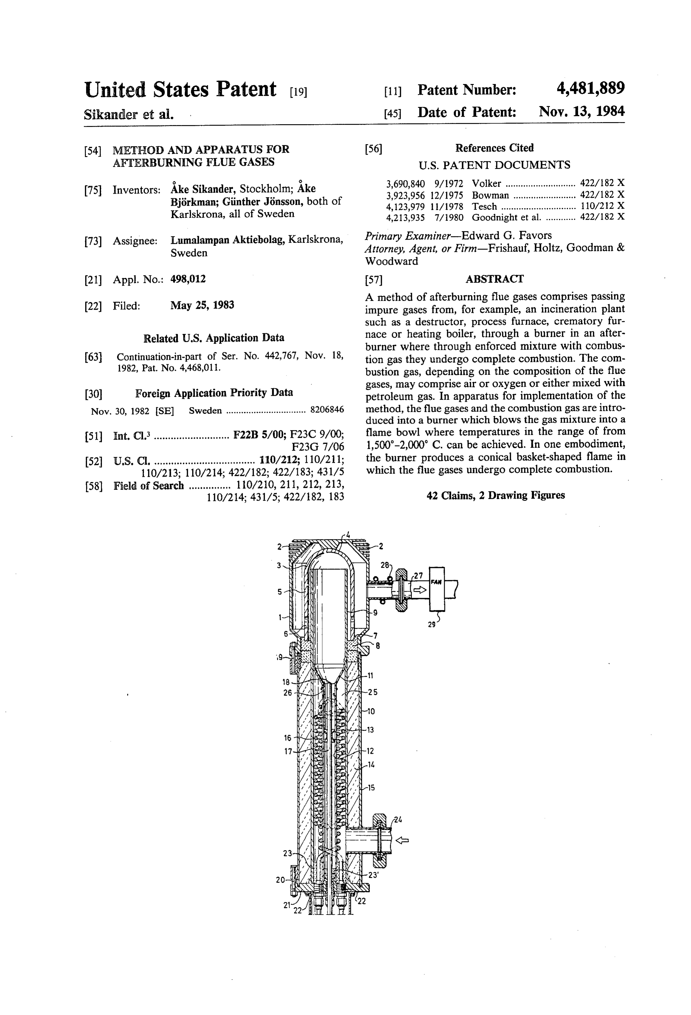
United States Patent (19) 11 Patent Number: 4,481,889 Sikander et al. (45. Date of Patent: Nov. 13, 1984 54 METHOD AND APPARATUS FOR 56) References Cited AFTERBURNING FILUE GASES U.S. PATENT DOCUMENTS 75 Inventors: Åke Sikander, Stockholm; Áke 3,690,840 9/1972 Volker ............................ 422/82 X 3,923,956 12/1975 Bowman ...... ... 422/182 X
Björkman; Ginther Jönsson, both of 4,123,979 1 1/1978 Tesch ................... ... 110/212 X Karlskrona, all of Sweden 4,213,935 7/1980 Goodnight et al. ............ 422/82 X 73) Assignee: Lumalampan Aktiebolag, Karlskrona, Primary Examiner-Edward G. Favors Sweden Attorney, Agent, or Firm-Frishauf, Holtz, Goodman & Woodward (21) Appl. No.: 498,012 (57) ABSTRACT A method of afterburning flue gases comprises passing (22 Filed: May 25, 1983 impure gases from, for example, an incineration plant such as a destructor, process furnace, crematory fur
Related U.S. Application Data nace or heating boiler, through a burner in an after burner where through enforced mixture with combus 63 Continuation-in-part of Ser. No. 442,767, Nov. 18, tion gas they undergo complete combustion. The com 1982, Pat. No. 4,468,011. bustion gas, depending on the composition of the flue gases, may comprise air or oxygen or either mixed with 30 Foreign Application Priority Data petroleum gas. In apparatus for implementation of the Nov. 30, 1982 SE Sweden ................................ 8206846 method, the flue gases and the combustion gas are intro duced into a burner which blows the gas mixture into a 51) Int. Cl. ........................... F22B5/00; F23C 9/00; flame bowl where temperatures in the range of from F23G 7/06 1,500-2,000 C. can be achieved. In one embodiment, 52 U.S.C. .................................... 110/212; 110/211; the burner produces a conical basket-shaped flame in 110/213; 110/214; 422/182; 422/183; 431/5 which the flue gases undergo complete combustion.
110/214; 431/5; 422/182, 183 42 Claims, 2 Drawing Figures
Page 2
Drawing sheet — no readable text.
Page 3
Drawing sheet — no readable text.
Page 4
METHOD AND APPARATUS FOR BRIEF DESCRIPTION OF THE DRAWINGS
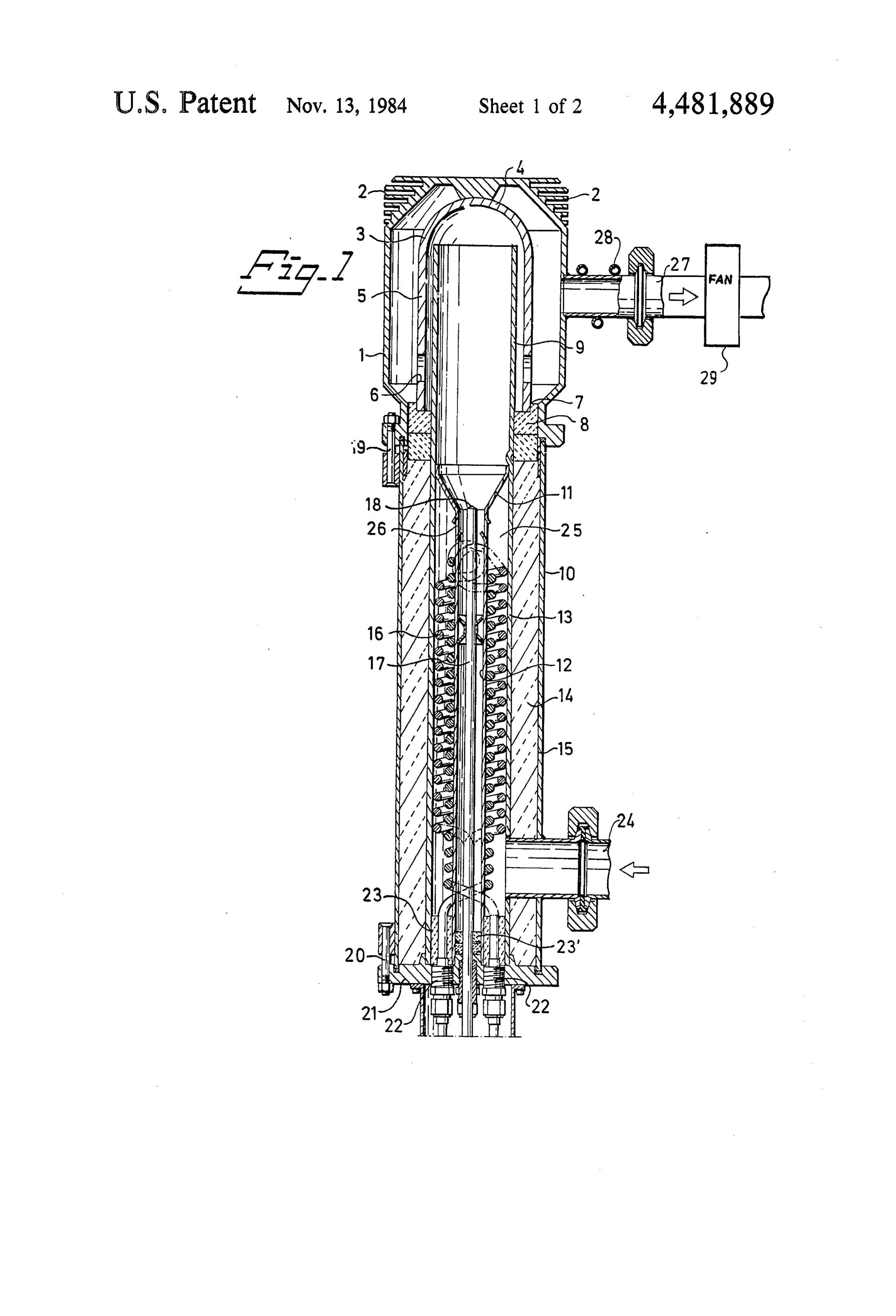
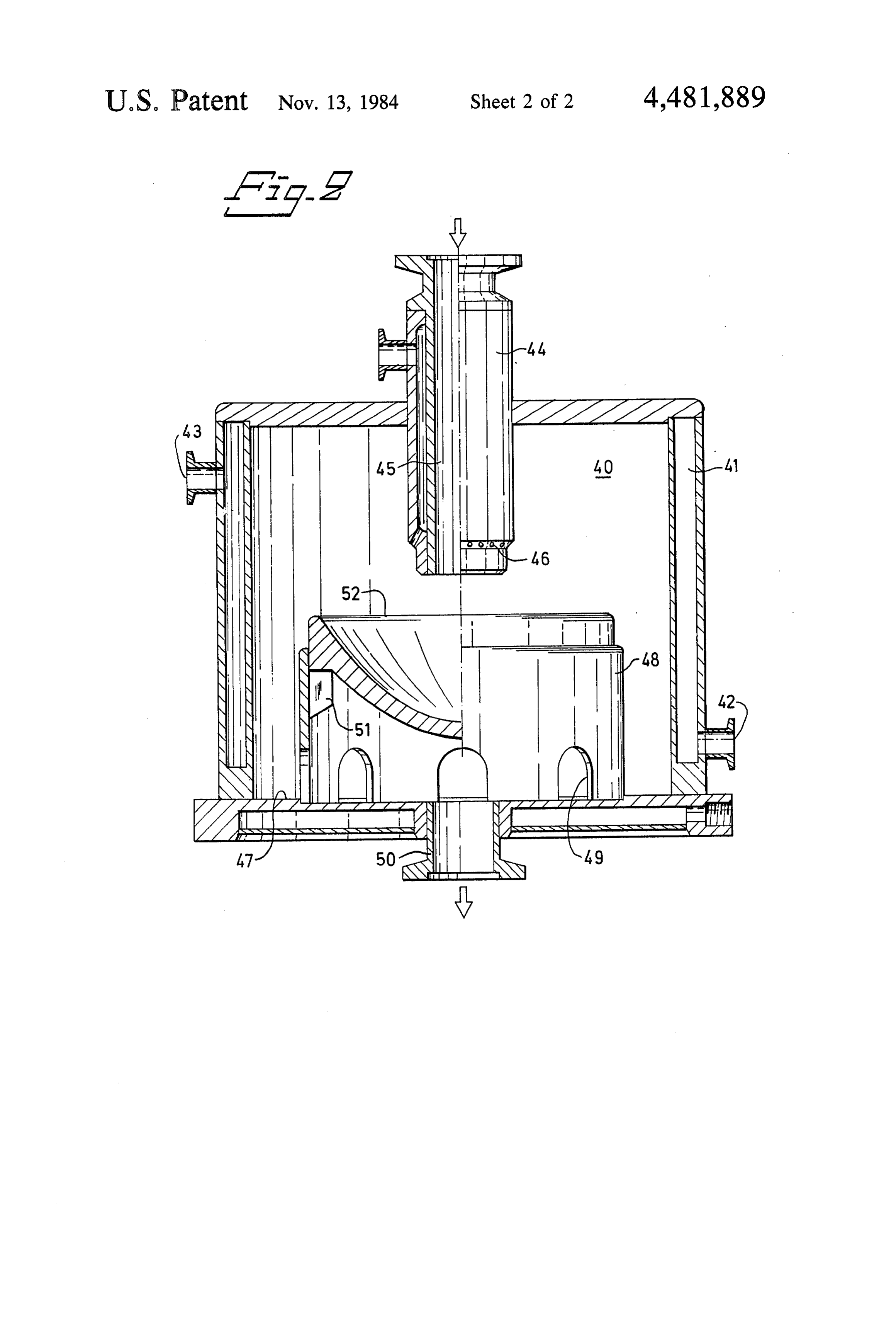
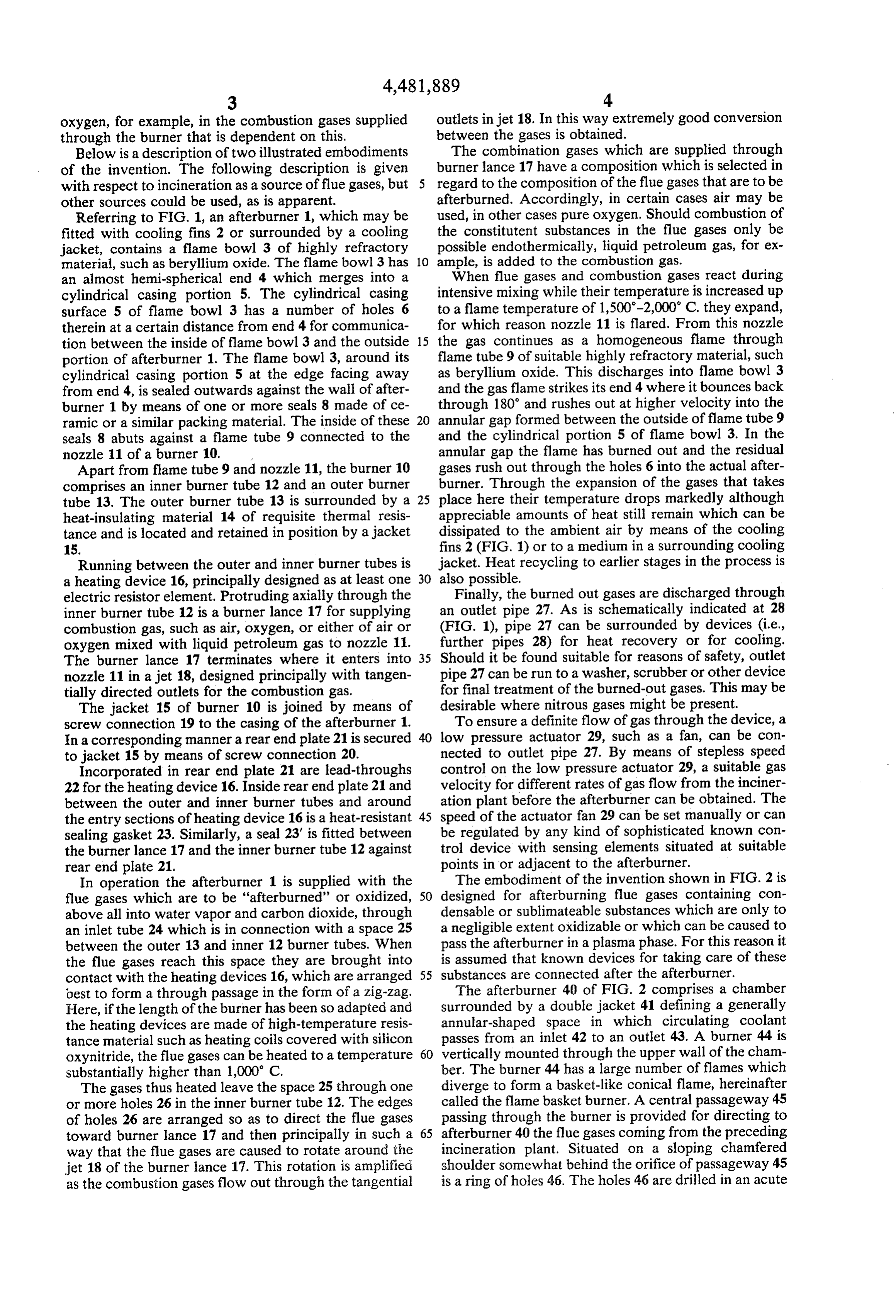
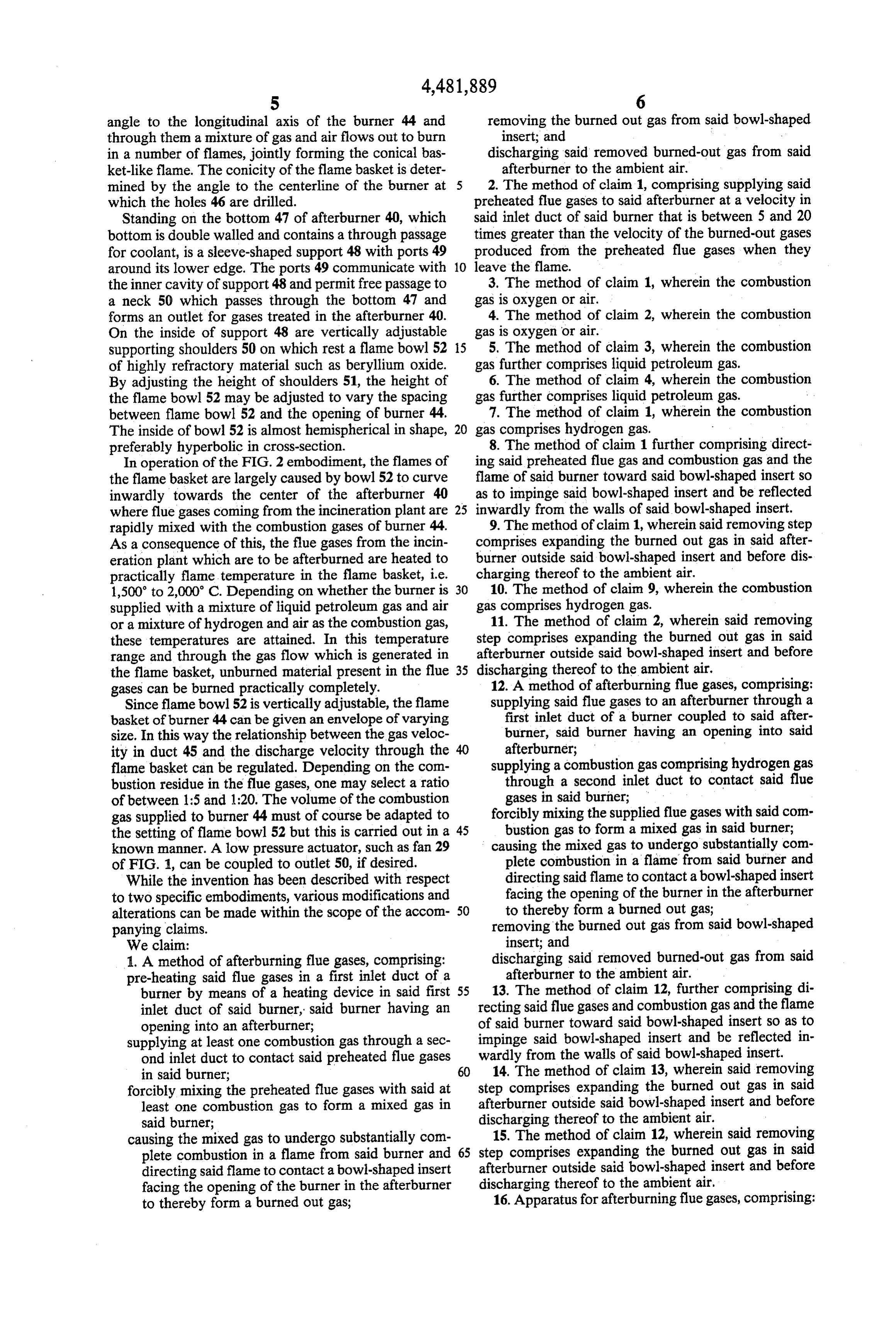
AFTERBURNING FLUE GASES FIG. 1 illustrates a longitudinal cross section of one embodiment of an afterburner of the present invention;
APPLICATION FIG. 2 illustrates a longitudinal cross section of an This is a continuation-in-part of Application Ser. No. other embodiment of an afterburner of the invention. 442,767, filed Nov. 18, 1982 U.S. Pat. No. 4468,011. DETAILED DESCRIPTION U.S. Application Ser. No. 442,767 filed Nov. 18, 1982 10 Before describing the invention in detail, a study of (corresponding to Sweden Application No. 8107177-1 the method of afterburning flue gases from household filed in Sweden on Dec. 1, 1981), the entire contents of refuse is discussed below to aid in an understanding of which is incorporated herein by reference. the invention.
BACKGROUND OF THE INVENTION In order to design and dimension an afterburner for 15 this pupose it is necessary to know what decomposition
The present invention relates to a method and appara products are formed and the quantities in which they tus for achieving the complete combustion of gases will coming from certain combustion reactions, and more basednormally on the be burned per unit of time. A calculation decomposition of 1 kg of polyethylene particularly to such a method and apparatus using an plastic in an incinerator and its transformation for the “afterburner' or secondary combustion chamber. 20
At present, a number of combustion processes are pene is performed by means1-pentene, most part into 1-hexene, propane and pro of the equation below. The carried out in which both the intended fuel and pollut thermal rate of decomposition for polyethylene poly ants take part in and undergo combustion to a greater or lesser degree. Afterburners have long been used on jet mers in a vacuum is determined through this and a rough estimate is made of the decomposition of polyeth engines for aircraft, although not for the purpose of ylene plastic under the conditions prevailing in the
achieving complete combustion of aviation fuel for incinerator.
environmental reasons but rather in order to attain K-Ae-(E/RT) higher performance. Exhaust emission control devices K= velocity constant (S-1) for motor vehicle engines are not really afterburning A= Arrhenius factor (S-) devices but rather arrangements for recirculating the 30 E=activation energy (KJ-mol-) exhaust gases. R=gas constant (8.314 J. K.-mol-1) In the case of incinerators for refuse, destructors and T=temperature (K.) Through such calculation and process furnaces in industry, as well as heating boilers, experiments it has been found that polyethylene combustion is carried to a stage comprising a balance 35 plastic decomposes in a vacuum at a rate of about between what is economical in terms of a return on the 1% per minute at 415 C. It accordingly takes process and what is required by the environmental pro about one and a half hours to decompose 1 kg of tection authorities. A common method of reducing the polyethylene plastic at a temperature of 415 C. degree of pollution in the emissions is to use a flue gas Under actual conditions the process in the incinera filter or flue gas scrubber. However, the problem of tor would cause decomposition of 10-15 g of poly disposing of what has been collected in the filters or ethylene per minute, corresponding to 6-9 liters/- scrubbing fluids still remains. A conventional method of min of gas. To afterburn this gas and to maintain a reducing the degree of pollution in the nearby environ temperature of 1,500-2,000' C. in the afterburn ment is to use tall chimneys to send the pollutants up for flame, in combination with the capability of retain dilution in the higher atmospheric layers. The effect of 45 ing a closed flame volume from which the amount such measures is becoming increasingly apparent in of gas given off from the refuse charge cannot Scandinavian forest areas where sulphurous acid from escape without complete combustion, the follow tall chimneys at incineration plants on the Continent ing amounts of gas are required for the afterburner rains down. The operating philosophy at destructors burner:
and refuse incineration plants has mostly been to reduce 50 LPG 0.2-0.3 m3/h (NTP) the concentration of malodorous substances in the flue Air 5-8 m3/h (NTP) gases. To the extent that tall chimneys have proved A burner design to ensure the aforementioned closed inadequate the incinerators have therefore been oper flame, in which complete conversion between flue gas ated at nighttime when few people are out and about. and combustion gas is attained, is described below. The same procedure has long been adopted to crema 55 Scaling up the afterburner to a larger size cannot be tory funaces-for ethical reason. carried to unlimited lengths, and where extremely large From the foregoing, it will be evident that numerous capacity is required, several afterburners will have to be incineration plants exist where it is desirable to reduce connected in parallel.
the content of pollutants in the flue gases. In the com The afterburner(s) can be controlled by known ion bustion of household refuse alone it is possible to trace 60 analyzing sensing devices positioned in the outlet of the some 50 substances, stemming from different plastic afterburner, which known devices can be used to regu materials, in the flue gases. By means of the present late the selection of any combustion gas admixture, e.g. invention it is possible to convert the vast majority of liquid petroleum gas in air or hydrogen in air, when the these to water vapor and carbon dioxide. temperature must be raised in order to achieve complete The object of the present invention is to provide a 65 combustion. Normally, the temperature range in the method and a device for transforming unburned flue gas afterburner is preset on the basis of empirical knowl components from incineration plants into harmless sub edge about the composition of the gases coming from stances by means of afterburning. the incineration plant and the admixture/surplus of
Page 5
oxygen, for example, in the combustion gases supplied outlets in jet 18. In this way extremely good conversion through the burner that is dependent on this. between the gases is obtained.
Below is a description of two illustrated embodiments The combination gases which are supplied through of the invention. The following description is given burner lance 17 have a composition which is selected in with respect to incineration as a source offlue gases, but regard to the composition of the flue gases that are to be other sources could be used, as is apparent. afterburned. Accordingly, in certain cases air may be Referring to FIG. 1, an afterburner 1, which may be used, in other cases pure oxygen. Should combustion of fitted with cooling fins 2 or surrounded by a cooling the constitutent substances in the flue gases only be jacket, contains a flame bowl 3 of highly refractory possible endothermically, liquid petroleum gas, for ex material, such as beryllium oxide. The flame bowl 3 has 10 ample, is added to the combustion gas. an almost hemi-spherical end 4 which merges into a When flue gases and combustion gases react during cylindrical casing portion 5. The cylindrical casing intensive mixing while their temperature is increased up surface 5 of flame bowl 3 has a number of holes 6 to a flame temperature of 1,500-2,000° C. they expand, therein at a certain distance from end 4 for communica for which reason nozzle 11 is flared. From this nozzle tion between the inside of flame bowl 3 and the outside 15 the gas continues as a homogeneous flame through portion of afterburner 1. The flame bowl 3, around its flame tube 9 of suitable highly refractory material, such cylindrical casing portion 5 at the edge facing away as beryllium oxide. This discharges into flame bowl 3 from end 4, is sealed outwards against the wall of after and the gas flame strikes its end 4 where it bounces back burner 1 by means of one or more seals 8 made of ce through 180' and rushes out at higher velocity into the ramic or a similar packing material. The inside of these 20 annular gap formed between the outside of flame tube 9 seals 8 abuts against a flame tube 9 connected to the and the cylindrical portion 5 of flame bowl 3. In the nozzle 11 of a burner 10. annular gap the flame has burned out and the residual Apart from flame tube 9 and nozzle 11, the burner 10 gases rush out through the holes 6 into the actual after comprises an inner burner tube 12 and an outer burner burner. Through the expansion of the gases that takes tube 13. The outer burner tube 13 is surrounded by a 25 place here their temperature drops markedly although heat-insulating material 14 of requisite thermal resis appreciable amounts of heat still remain which can be tance and is located and retained in position by a jacket dissipated to the ambient air by means of the cooling 15. fins 2 (FIG. 1) or to a medium in a surrounding cooling Running between the outer and inner burner tubes is jacket. Heat recycling to earlier stages in the process is a heating device 16, principally designed as at least one 30 also possible.
electric resistor element. Protruding axially through the Finally, the burned out gases are discharged through inner burner tube 12 is a burner lance 17 for supplying an outlet pipe 27. As is schematically indicated at 28 combustion gas, such as air, oxygen, or either of air or (FIG. 1), pipe 27 can be surrounded by devices (i.e., oxygen mixed with liquid petroleum gas to nozzle 11. further pipes 28) for heat recovery or for cooling. The burner lance 17 terminates where it enters into 35 Should it be found suitable for reasons of safety, outlet nozzle 11 in a jet 18, designed principally with tangen pipe 27 can be run to a washer, scrubber or other device tially directed outlets for the combustion gas. for final treatment of the burned-out gases. This may be The jacket 15 of burner 10 is joined by means of desirable where nitrous gases might be present. screw connection 19 to the casing of the afterburner 1. To ensure a definite flow of gas through the device, a In a corresponding manner a rear end plate 21 is secured 40 low pressure actuator 29, such as a fan, can be con to jacket 15 by means of screw connection 20. nected to outlet pipe 27. By means of stepless speed Incorporated in rear end plate 21 are lead-throughs control on the low pressure actuator 29, a suitable gas 22 for the heating device 16. Inside rear end plate 21 and velocity for different rates of gas flow from the inciner between the outer and inner burner tubes and around ation plant before the afterburner can be obtained. The the entry sections of heating device 16 is a heat-resistant 45 speed of the actuator fan 29 can be set manually or can sealing gasket 23. Similarly, a seal 23' is fitted between be regulated by any kind of sophisticated known con the burner lance 17 and the inner burner tube 12 against trol device with sensing elements situated at suitable rear end plate 21. points in or adjacent to the afterburner. In operation the afterburner 1 is supplied with the The embodiment of the invention shown in FIG. 2 is flue gases which are to be "afterburned' or oxidized, 50 designed for afterburning flue gases containing con above all into water vapor and carbon dioxide, through densable or sublimateable substances which are only to an inlet tube 24 which is in connection with a space 25 a negligible extent oxidizable or which can be caused to between the outer 13 and inner 12 burner tubes. When pass the afterburner in a plasma phase. For this reason it the flue gases reach this space they are brought into is assumed that known devices for taking care of these contact with the heating devices 16, which are arranged 55 substances are connected after the afterburner. best to form a through passage in the form of a zig-zag. The afterburner 40 of FIG. 2 comprises a chamber Here, if the length of the burner has been so adapted and surrounded by a double jacket 41 defining a generally the heating devices are made of high-temperature resis annular-shaped space in which circulating coolant tance material such as heating coils covered with silicon passes from an inlet 42 to an outlet 43. A burner 44 is oxynitride, the flue gases can be heated to a temperature 60 vertically mounted through the upper wall of the cham substantially higher than 1,000 C. ber. The burner 44 has a large number of flames which The gases thus heated leave the space 25 through one diverge to form a basket-like conical flame, hereinafter or more holes 26 in the inner burner tube 12. The edges called the flame basket burner. A central passageway 45 of holes 26 are arranged so as to direct the flue gases passing through the burner is provided for directing to toward burner lance 17 and then principally in such a 65 afterburner 40 the flue gases coming from the preceding way that the flue gases are caused to rotate around the incineration plant. Situated on a sloping chamfered jet 18 of the burner lance 17. This rotation is amplified shoulder somewhat behind the orifice of passageway 45 as the combustion gases flow out through the tangential is a ring of holes 46. The holes 46 are drilled in an acute
Page 6
angle to the longitudinal axis of the burner 44 and removing the burned out gas from said bowl-shaped through them a mixture of gas and air flows out to burn insert; and in a number of flames, jointly forming the conical bas discharging said removed burned-out gas from said ket-like flame. The conicity of the flame basket is deter afterburner to the ambient air. mined by the angle to the centerline of the burner at 5 2. The method of claim 1, comprising supplying said which the holes 46 are drilled. preheated flue gases to said afterburner at a velocity in Standing on the bottom 47 of afterburner 40, which said inlet duct of said burner that is between 5 and 20 bottom is double walled and contains a through passage times greater than the velocity of the burned-out gases for coolant, is a sleeve-shaped support 48 with ports 49 produced from the preheated flue gases when they around its lower edge. The ports 49 communicate with 10 leave the flame.
the inner cavity of support 48 and permit free passage to 3. The method of claim 1, wherein the combustion a neck 50 which passes through the bottom 47 and gas is oxygen or air.
forms an outlet for gases treated in the afterburner 40. 4. The method of claim 2, wherein the combustion On the inside of support 48 are vertically adjustable gas is oxygen or air.
supporting shoulders 50 on which rest a flame bowl 52 15 5. The method of claim 3, wherein the combustion of highly refractory material such as beryllium oxide. gas further comprises liquid petroleum gas. By adjusting the height of shoulders 51, the height of 6. The method of claim 4, wherein the combustion the flame bowl 52 may be adjusted to vary the spacing gas further comprises liquid petroleum gas. between flame bowl 52 and the opening of burner 44. 7. The method of claim 1, wherein the combustion The inside of bowl 52 is almost hemispherical in shape, 20 gas comprises hydrogen gas.
preferably hyperbolic in cross-section. 8. The method of claim 1 further comprising direct In operation of the FIG. 2 embodiment, the flames of ing said preheated flue gas and combustion gas and the the flame basket are largely caused by bowl 52 to curve flame of said burner toward said bowl-shaped insert so inwardly towards the center of the afterburner 40 as to impinge said bowl-shaped insert and be reflected where flue gases coming from the incineration plant are 25 inwardly from the walls of said bowl-shaped insert. rapidly mixed with the combustion gases of burner 44. 9. The method of claim 1, wherein said removing step As a consequence of this, the flue gases from the incin comprises expanding the burned out gas in said after eration plant which are to be afterburned are heated to burner outside said bowl-shaped insert and before dis practically flame temperature in the flame basket, i.e. charging thereof to the ambient air. 1,500 to 2,000 C. Depending on whether the burner is 30 10. The method of claim 9, wherein the combustion supplied with a mixture of liquid petroleum gas and air gas comprises hydrogen gas.
or a mixture of hydrogen and air as the combustion gas, 11. The method of claim 2, wherein said removing these temperatures are attained. In this temperature step comprises expanding the burned out gas in said range and through the gas flow which is generated in afterburner outside said bowl-shaped insert and before the flame basket, unburned material present in the flue 35 discharging thereof to the ambient air. gases can be burned practically completely. 12. A method of afterburning flue gases, comprising: Since flame bowl 52 is vertically adjustable, the flame supplying said flue gases to an afterburner through a basket of burner 44 can be given an envelope of varying first inlet duct of a burner coupled to said after size. In this way the relationship between the gas veloc burner, said burner having an opening into said ity in duct 45 and the discharge velocity through the 40 afterburner;
flame basket can be regulated. Depending on the com supplying a combustion gas comprising hydrogen gas bustion residue in the flue gases, one may select a ratio through a second inlet duct to contact said flue of between 1:5 and 1:20. The volume of the combustion gases in said burner;
gas supplied to burner 44 must of course be adapted to forcibly mixing the supplied flue gases with said com the setting of flame bowl 52 but this is carried out in a 45 bustion gas to form a mixed gas in said burner; known manner. A low pressure actuator, such as fan 29 causing the mixed gas to undergo substantially com of FIG. 1, can be coupled to outlet 50, if desired. plete combustion in a flame from said burner and While the invention has been described with respect directing said flame to contact a bowl-shaped insert to two specific embodiments, various modifications and facing the opening of the burner in the afterburner alterations can be made within the scope of the accom 50 to thereby form a burned out gas; panying claims. removing the burned out gas from said bowl-shaped We claim: insert; and 1. A method of afterburning flue gases, comprising: discharging said removed burned-out gas from said pre-heating said flue gases in a first inlet duct of a afterburner to the ambient air. burner by means of a heating device in said first 55 13. The method of claim 12, further comprising di inlet duct of said burner, said burner having an recting said flue gases and combustion gas and the flame opening into an afterburner; of said burner toward said bowl-shaped insert so as to supplying at least one combustion gas through a sec impinge said bowl-shaped insert and be reflected in ond inlet duct to contact said preheated flue gases wardly from the walls of said bowl-shaped insert. in said burner; 60 14. The method of claim 13, wherein said removing forcibly mixing the preheated flue gases with said at step comprises expanding the burned out gas in said least one combustion gas to form a mixed gas in afterburner outside said bowl-shaped insert and before said burner; discharging thereof to the ambient air. causing the mixed gas to undergo substantially com 15. The method of claim 12, wherein said removing plete combustion in a flame from said burner and 65 step comprises expanding the burned out gas in said directing said flame to contact a bowl-shaped insert afterburner outside said bowl-shaped insert and before facing the opening of the burner in the afterburner discharging thereof to the ambient air, to thereby form a burned out gas; 16. Apparatus for afterburning flue gases, comprising:
Page 7
an afterburner (1,40); 25. The apparatus of claim 24, wherein said first inlet a burner (10,44) comprising an end protruding into duct (25) has an inner tube (12) having holes (26) the said afterburner and means for generating a flame; edges of which are arranged to direct the flue gases to a bowl-shaped flame bowl (3,52) located opposite the flow tangentially against said jet (18) of said burner protruding end of said burner for catching and lance.
reflecting the flame from said burner; 26. The apparatus of claim 24, further comprising a first inlet duct (25,45) passing through said burner means (2,41) surrounding said afterburner (1,40) for along the longitudinal axis thereof, said first inlet dissipating surplus heat therefrom.
duct comprising means (16) for heating said flue 27. The apparatus of claim 24, wherein said first inlet gases and a pathway for conveying said heated flue 10 duct (45) for said flue gases has an outlet orifice in said gases into said burner flame; afterburner and is surrounded concentrically by said a second inlet duct for supplying at least one combus second inlet duct for supplying said at least one combus tion gas to said burner flame; and tion gas, said second inlet duct discharging said at least an outlet (27.50) provided in said afterburner for one combustion gas through a plurality of holes (46) conveying burned-out flue gases out of said burner. 15 located behind said outlet orifice of said first inlet duct 17. The apparatus of claim 16, further comprising a (45).
burner lance (17) inside said burner (10) and coupled to 28. The apparatus of claim 27, wherein said plurality said second inlet duct for introducing said combustion of holes (46) are directed at an acute angle with respect gas to said burner flame, said burner lance comprising a to the longitudinal axis of said burner (10). jet (18) having a plurality of tangentially directed exits 20 29. The apparatus of claim 24, further comprising for directing said combustion gas into said burner flame. means (51) for adjusting the position of said flame bowl 18. The apparatus of claim 17, wherein said first inlet (3,52) relative to said burner (10,44) in the direction of duct (25) has an inner tube (12) having holes (26) the the longitudinal axis of said burner. edges of which are arranged to direct the flue gases to 30. The apparatus of claim 24, further comprising an flow tangentially against said jet (18) of said burner 25 expansion chamber coupled to said outlet for expanding lance. said burned-out flue gases before said burned out flue 19. The apparatus of claim 16, further comprising gases are fed to said outlet.
means (2,41) surrounding said afterburner (1,40) for 31. Apparatus for afterburning flue gases, comprising: dissipating surplus heat therefrom. an afterburner (1,40);
20. The apparatus of claim 16, wherein said first inlet 30 a burner (10,44) having an end protruding into said duct (45) for said flue gases has an outlet orifice in said afterburner;
afterburner and is surrounded concentrically by said a bowl-shaped flame bowl (3,52) located opposite the second inlet duct for supplying said at least one combus protruding end of said burner for catching and tion gas, said second inlet duct discharging said at least reflecting the flame from said burner; one combustion gas through a plurality of holes (46) 35 a first inlet duct (25,45) passing through said burner located behind said outlet orifice of said first inlet duct along the longitudinal axis thereof, said first inlet (45). duct comprising a pathway for conveying said flue 21. The apparatus of claim 20, wherein said plurality gases into said burner flame and an outlet orifice; of holes (46) are directed at an acute angle with respect a second inlet duct for supplying at least one combus to the longitudinal axis of said burner (10). 40 tion gas to said burner flame, said outlet orifice of 22. The apparatus of claim 16, further comprising said first inlet duct being surrounded concentri means (51) for adjusting the position of said flame bowl cally by said second inlet duct, said second inlet (3,52) relative to said burner (10,44) in the direction of duct discharging said at least one combustion gas the longitudinal axis of said burner. through a plurality of holes (46) located behind 23. The apparatus of claim 16, further comprising an 45 said outlet orifice of said first inlet duct (45); and expansion chamber coupled to said outlet for expanding an outlet (27.50) provided in said afterburner for said burned-out flue gases before said burned out flue conveying burned-out flue gases out of said burner. gases are fed to said outlet. 32. The apparatus of claim 31, further comprising 24. Apparatus for afterburning flue gases, comprising: means (2,41) surrounding said afterburner (1,40) for an afterburner (1,40); 50 dissipating surplus heat therefrom. a burner (10,44) having an end protruding into said 33. The apparatus of claim 31, wherein said plurality afterburner; of holes (46) are directed at an acute angle with respect a bowl-shaped flame bowl (3,52) located opposite the to the longitudinal axis of said burner (10). protruding end of said burner for catching and 34. The apparatus of claim 31, further comprising reflecting the flame from said burner; 55 means (51) for adjusting the position of said flame bowl a first inlet duct (25,45) passing through said burner (3,52) relative to said burner (10,44) in the direction of along the longitudinal axis thereof, said first inlet the longitudinal axis of said burner.
duct comprising a pathway for conveying said flue 35. The apparatus of claim 31, further comprising an gases into said burner flame; expansion chamber coupled to said outlet for expanding a second inlet duct for supplying through an end 60 said burned-out flue gases before said burned out flue thereof at least one combustion gas to said burner gases are fed to said outlet.
flame, said second inlet duct comprising a burner 36. Apparatus for afterburning flue gases, comprising: lance at said end thereof, said burner lance com an afterburner (140);
prising a jet (18) having a plurality of tangentially a burner (10,44) having an end protruding into said directed exits for directing said at least one com 65 afterburner;
bustion gas into said burner flame; and a bowl-shaped flame bowl (3,52) located opposite the an outlet (27,50) provided in said afterburner for protruding end of said burner for catching and conveying burned-out flue gases out of said burner. reflecting the flame from said burner;
Page 8
means (51) for adjusting the position of said flame flow tangentially against said jet (18) of said burner bowl (3,52) relative to said burner (10,44) in the lance.
direction of the longitudinal axis of said burner; 39. The apparatus of claim 36, further comprising a first inlet duct (25,45) passing through said burner means (2,41) surrounding said afterburner (1,40) for along the longitudinal axis thereof, said first inlet dissipating surplus heat therefrom. duct comprising a pathway for conveying said flue 40. The apparatus of claim 36, wherein said first inlet gases into said burner flame; duct (45) for said flue gases has an outlet orifice in said a second inlet duct for supplying at least one combus afterburner and is surrounded concentrically by said tion gas to said burner flame; and second inlet duct for supplying said at least one combus an outlet (27.50) provided in said afterburner for 10 tion gas, said second inlet duct discharging said at least conveying burned-out flue gases out of said burner. one combustion gas through a plurality of holes (46) 37. The apparatus of claim 36, further comprising a located behind said outlet orifice of said first inlet duct burner lance (17) inside said burner (10) and connected (45).
to said second inlet duct for introducing said combus 41. The apparatus of claim 40, wherein said plurality tion gas to said burner flame, said burner lance compris 15 of holes (46) are directed at an acute angle with respect ing a jet (18) having a plurality of tangentially directed to the longitudinal axis of said burner (10). exits for directing said combustion gas into said burner 42. The apparatus of claim 36, further comprising an flame. expansion chamber coupled to said outlet for expanding 38. The apparatus of claim 37, wherein said first inlet said burned-out flue gases before said burned-out flue duct (25) has an inner tube (12) having holes (26) the 20 gases are fed to said outlet. k k edges of which are arranged to direct the flue gases to
Provenance
- Collection
- Cited prior art
- Original PDF
- patentimages.storage.googleapis.com →
- Filed
- 1983-05-25
- Pages
- 8
- Method
- pdftotext (the PDF's own text layer) + pdftoppm 300dpi page scans
- Source
- Google Patents bibliographic record
- Granted
- 1984-11-13
- Inventors
- Ake Sikander; Ake Bjorkman; Gunther Jonsson; Lumalampan AB
- Transcribed from
- patentimages.storage.googleapis.com →