patent · US5169605
Process and installation for the combustion of toxic gaseous effluents bereft of oxygen
8 December 1992
Page 1 — bibliographic record
United States Patent (19) 11 Patent Number: 5,169,605 Carpentier 45 Date of Patent: Dec. 8, 1992 (54 PROCESS AND INSTALLATION FOR THE 56) References Cited COMBUSTION OF TOXC GASEOUS U.S. PATENT DOCUMENTS
EFFLUENTS BEREFT OF OXYGEN
75 Inventor: Serge Carpentier, Villecresnes, 3,552,334 1/1971 Springer et al. .................... 10/24 France 4,033,725 7/1977 Reed et al. .......................... 423/248 4,145,979 3/1979 Lilley et al. ......................... 10/214 4,199,549 4/1980 Wilt, Jr. et al. .... ... 423/245.3 (73) Assignee: Societe Generale Pour les Techniques 4,801,437 1/1989 Konagaya et al. . 423/210 Novelles SGN, 4,920,898 5/1990 Solbes et al. ........................ 10/214 Saint-Quentin-en-Yvelines Cedex,
France Primary. Examiner-Robert J. Warden
Assistant Examiner-Krisanne M. Thornton (21) Appl. No.: 675,930 Attorney, Agent, or Firm-Fulwider, Patton, Lee & Utecht 22 PCT Filed: Sep. 4, 1990 57 ABSTRACT 86 PCT No.: PCT/FR90/00641 Process for the combustion of toxic gaseous effluents bereft of oxygen in a flame, comprising an inner cone (8)
S 371 Date: May 3, 1991 supplied with combustible gas (6) and with so-called S 102(e) Date: May 3, 1991 primary combustion-suppporting gas (7). Said gaseous effluent (10) and a so-called secondary combustion-sup 87 PCT Pub. No.: WO91/03685 porting gas (9) are introduced separately at the level of said inner cone, said secondary combustion-supporting
PCT Pub. Date: Mar. 21, 1991 gas being introduced in the form of at least one jet 30 Foreign Application Priority Data directed towards the axis (D) of said inner cone at a flowrate and speed sufficient to ensure an excess of
Sep. 4, 1989 FR) France ................................ 89 1548 combustion-supporting gas, the maintenance of temper ature and to create a turbulent gaseous mass at the level 51) Int. Cl. ....................... B01D 50/00; B01D 53/34 of said inner cone; the toxic gaseous effluent (10) being 52 U.S. Cl. .................................... 422/182; 422/183; introduced into said turbulent gaseous mass. Said pro 10/210; 10/212; 110/213; 110/214; 423/24; cess is carried out under a depression. It also relates to 423/245.3 an installation for carrying out said process.
58) Field of Search ............................... 422/182, 183;
110/210-214; 423/210, 24, 245.3, 248 15 Claims, 2 Drawing Sheets
Page 2
Drawing sheet — no readable text.
Page 3
Drawing sheet — no readable text.
Page 4
Said gaseous effluents may also come from the nu
PROCESS AND INSTALLATION FOR THE clear industry. It may be question of radio-active gases COMBUSTION OF TOXIC GASEOUSEFFLUENTS of pyrolysis and/or radio-active gases laden with trit
The inner cone of the flame is obtained from a con
The invention relates to a process and an installation ventional burner disposed at the head of the combustion for the destruction by combustion of toxic gaseous ef zone, supplied with combustible gas (natural gas for fluents bereft of oxygen. example) and combustion-supporting gas (air for exam The problem of the elimination of such effluents is ple). This combustion-supporting gas is called primary raised in particular in integrated circuit factories where O in the text of the present application in order to distin gases laden with arsenic hydrides (arsines), and/or guish it from the other streams of combustion-support phosphorus hydrides (phosphines) and/or silicon hy ing gas. The flowrate of this primary combustion-sup drides (silanes) . . . are employed to dope the materials. porting gas is advantageously adjusted so as to ensure These gases are toxic and the gaseous stream contain combustion with a small excess of combustion-support ing them must absolutely be purified before being re 15 ing gas (about 10%).
jected into the atmosphere. According to the invention, so-called secondary A known process of treatment consists in burning combustion-supporting gas is sent towards the inner said gases; the combustion products not being toxic or cone inantheexcess form of jet(s), at a sufficient flowrate to being able to be easily eliminated (for example by filtra 20 ensure respect to the of combustion-supporting gas, with quantity necessary for the combustion of tion for arsenous oxide). the toxic effluent, and at a speed sufficient to create a Patent No. FR 87 03729 published under No. 2612 turbulent gaseous mass at the level of the inner cone. 606 describes such a process with its associated device. The secondary combustion-supporting gas is for ex According to this Patent, the effluent is conducted into ample a combustion zone via a central conduit surrounded by 25 The air.
flowrate and speed of the secondary combustion a pipe supplying the combustible gas, itself surrounded supporting gas are such that the appearance of the inner by three annular conduits supplying the combustion cone is modified: it changes colour, its shape is dis supporting air. Every effort is made to remain as long as turbed and eddying movements are observed. It is then possible in laminar flow even beyond the burner in said order to repel the inflammation zone in order to avoid 30 non isthatknownthe gaseous mass is turbulent. This phenome to the man skilled in the art.
the deposit of oxides on the burner. The flowrates and speeds of injection of the gases are regulated to that end. supporting gas and
The flowrate must speed of the secondary combustion also be determined in order to
To the same end, the stream of combustible gas consti ensure maintenance of the temperature in the zone of tutes a sheath for protecting the effluent with respect to combustion and the excess of combustion-supporting the combustion-supporting gas. 35 gaS.
Applicant is proposing at the present time a process The speeds may go up to several tens of m/s. of combustion in which, contrary to the prior art, a The secondary combustion-supporting gas is intro considerable turbulence is created. duced in the form of one or more jets directed towards More precisely, the invention has for its object a the axis of said inner cone. These jets may converge process for the combustion of toxic gaseous effluents 40 towards the axis of the inner cone or be directed so as to bereft of oxygen in a flame comprising an inner cone create an eddying movement of the combustion-sup supplied with combustible gas and so-called primary porting gas around said inner cone; in that case, too, the combustion-supporting gas, process carried out under orientation of the jet participates in the creation of the depression and in which said gaseous effluent and a turbulence.
so-called secondary combustion-supporting gas are in 45 The process of the invention is carried out, under troduced separately at the level of said inner cone, said depression or subambient pressure with respect to the secondary combustion-supporting gas being introduced atmosphere outside the zone of combustion (ambient in the form of at least one jet directed towards the axis atmosphere). Such a depression or subambient pressure of said inner cone at a sufficient flowrate and speed to makes it possible to avoid the formation of pockets of ensure an excess of combustion supporting gas, the 50 gas, to avoid a possible dispersion of the gases towards maintenance of temperature, and to create a turbulent the outside. Furthermore, it facilitates the extraction of gaseous mass at the level of said inner cone; the toxic the gases issuing from the installation in which the pro gaseous effluent being introduced in said turbulent gase cess is carried out.
OS 2.SS This depression or subambient pressure is of the order The invention therefore consists in a process of com 55 of 0.5 to 6 mbar (or 50 to 600 Pa). bustion of toxic gaseous effluents, bereft of oxygen. The secondary combustion-supporting gas is prefera Such effluents are not explosive per se. They may be bly supplied via two different circuits producing: come so in the presence of oxygen. at least one so-called fixed jet with constant flowrate They are constituted by a vector gas laden with in and speed, sufficient to obtain a turbulent gaseous mass purities. Said vector gas may be hydrogen, nitrogen, . . and the desired temperature of combustion; . or a mixture of gases. Air and oxygen are obviously at least one so-called modulatable jet with a variable excluded. flowrate to maintain the temperature; said jets also en Said gaseous effluents to be burned according to the suring the supply of excess combustion-supporting gas. process of the invention may, as indicated above, come The stream of modulatable (secondary) combustion from the electronic industry. Such effluents are laden 65 supporting gas cools the gaseous mass and makes it with hydride, particularly phosphines, arsines . . . and possible to reduce the temperature of the combustion /or silanes . . . and/or other chemical compounds con zone, if necessary. The absence of said current causes taining in particular B, P, As, Te, Se, Cl, F atoms. the temperature to rise, which may be accelerated by
Page 5
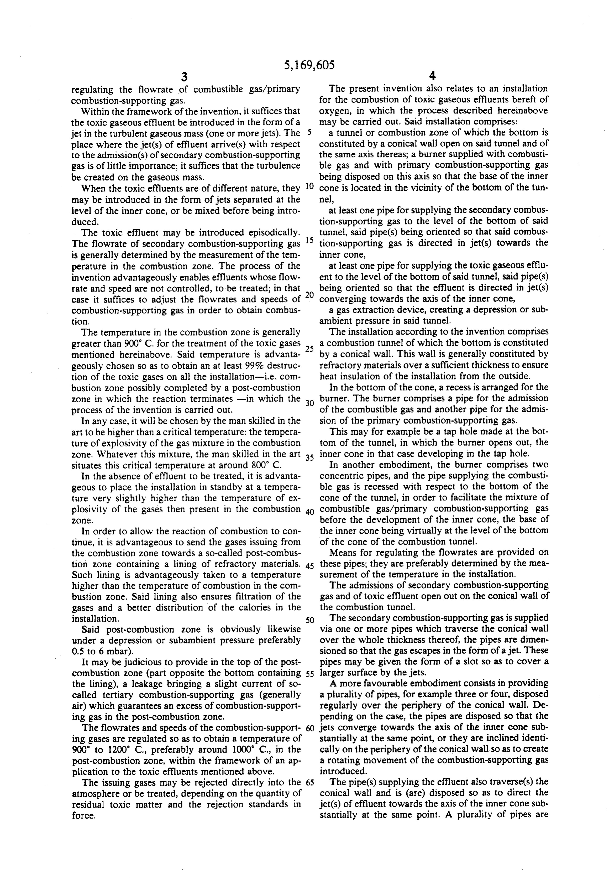
regulating the flowrate of combustible gas/primary The present invention also relates to an installation combustion-supporting gas. for the combustion of toxic gaseous effluents bereft of Within the framework of the invention, it suffices that oxygen, in which the process described hereinabove the toxic gaseous effluent be introduced in the form of a may be carried out. Said installation comprises: jet in the turbulent gaseous mass (one or more jets). The 5 a tunnel or combustion zone of which the bottom is place where the jet(s) of effluent arrive(s) with respect constituted by a conical wall open on said tunnel and of to the admission(s) of secondary combustion-supporting the same axis thereas; a burner supplied with combusti gas is of little importance; it suffices that the turbulence ble gas and with primary combustion-supporting gas be created on the gaseous mass. being disposed on this axis so that the base of the inner When the toxic effluents are of different nature, they O cone is located in the vicinity of the bottom of the tun may be introduced in the form of jets separated at the nel, level of the inner cone, or be mixed before being intro at least one pipe for supplying the secondary combus duced. tion-supporting gas to the level of the bottom of said The toxic effluent may be introduced episodically. 15 tunnel, said pipe(s) being oriented so that said combus The flowrate of secondary combustion-supporting gas tion-supporting gas is directed in jet(s) towards the is generally determined by the measurement of the tem inner cone, perature in the combustion zone. The process of the at least one pipe for supplying the toxic gaseous efflu invention advantageously enables effluents whose flow ent to the level of the bottom of said tunnel, said pipe(s) rate and speed are not controlled, to be treated; in that being oriented so that the effluent is directed in jet(s) case it suffices to adjust the flow rates and speeds of 20 converging towards the axis of the inner cone, combustion-supporting gas in order to obtain combus a gas extraction device, creating a depression or sub tion. ambient pressure in said tunnel. The temperature in the combustion zone is generally The installation according to the invention comprises greater than 900 C. for the treatment of the toxic gases 25 a combustion tunnel of which the bottom is constituted mentioned hereinabove. Said temperature is advanta by a conical wall. This wall is generally constituted by geously chosen so as to obtain an at least 99% destruc refractory materials over a sufficient thickness to ensure tion of the toxic gases on all the installation-i.e. com heat insulation of the installation from the outside. bustion zone possibly completed by a post-combustion In the bottom of the cone, a recess is arranged for the zone in which the reaction terminates -in which the 30 burner. The burner comprises a pipe for the admission process of the invention is carried out. of the combustible gas and another pipe for the admis In any case, it will be chosen by the man skilled in the sion of the primary combustion-supporting gas. art to be higher than a critical temperature: the tempera This may for example be a tap hole made at the bot ture of explosivity of the gas mixture in the combustion tom of the tunnel, in which the burner opens out, the zone. Whatever this mixture, the man skilled in the art 35 inner cone in that case developing in the tap hole. situates this critical temperature at around 800° C. In another embodiment, the burner comprises two In the absence of effluent to be treated, it is advanta concentric pipes, and the pipe supplying the combusti geous to place the installation in standby at a tempera ble gas is recessed with respect to the bottom of the ture very slightly higher than the temperature of ex cone of the tunnel, in order to facilitate the mixture of plosivity of the gases then present in the combustion combustible gas/primary combustion-supporting gas 2O2. before the development of the inner cone, the base of In order to allow the reaction of combustion to con the inner cone being virtually at the level of the bottom tinue, it is advantageous to send the gases issuing from of the cone of the combustion tunnel. the combustion zone towards a so-called post-combus Means for regulating the flowrates are provided on tion zone containing a lining of refractory materials. 45 these pipes; they are preferably determined by the mea Such lining is advantageously taken to a temperature surement of the temperature in the installation. higher than the temperature of combustion in the com The admissions of secondary combustion-supporting bustion zone. Said lining also ensures filtration of the gas and of toxic effluent open out on the conical wall of gases and a better distribution of the calories in the the combustion tunnel.
installation. 50 The secondary combustion-supporting gas is supplied Said post-combustion zone is obviously likewise via one or more pipes which traverse the conical wall under a depression or subambient pressure preferably over the whole thickness thereof, the pipes are dimen 0.5 to 6 mbar). sioned so that the gas escapes in the form of a jet. These It may be judicious to provide in the top of the post pipes may be given the form of a slot so as to cover a combustion zone (part opposite the bottom containing 55 larger surface by the jets.
the lining), a leakage bringing a slight current of so A more favourable embodiment consists in providing called tertiary combustion-supporting gas (generally a plurality of pipes, for example three or four, disposed air) which guarantees an excess of combustion-support regularly over the periphery of the conical wall. De ing gas in the post-combustion zone. pending on the case, the pipes are disposed so that the The flowrates and speeds of the combustion-support 60 jets converge towards the axis of the inner cone sub ing gases are regulated so as to obtain a temperature of stantially at the same point, or they are inclined identi 900' to 1200° C., preferably around 1000 C., in the cally on the periphery of the conical wall so as to create post-combustion zone, within the framework of an ap a rotating movement of the combustion-supporting gas plication to the toxic effluents mentioned above. introduced.
The issuing gases may be rejected directly into the 65 The pipe(s) supplying the effluent also traverse(s) the atmosphere or be treated, depending on the quantity of conical wall and is (are) disposed so as to direct the residual toxic matter and the rejection standards in jet(s) of effluent towards the axis of the inner cone sub force. stantially at the same point. A plurality of pipes are
Page 6
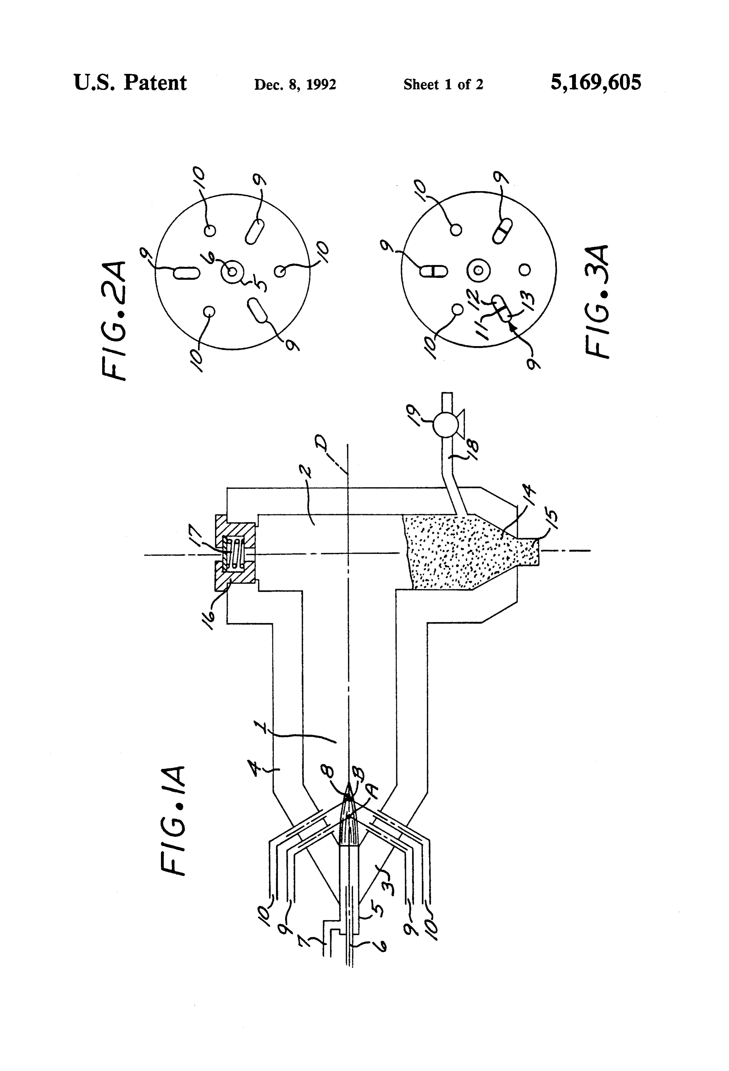
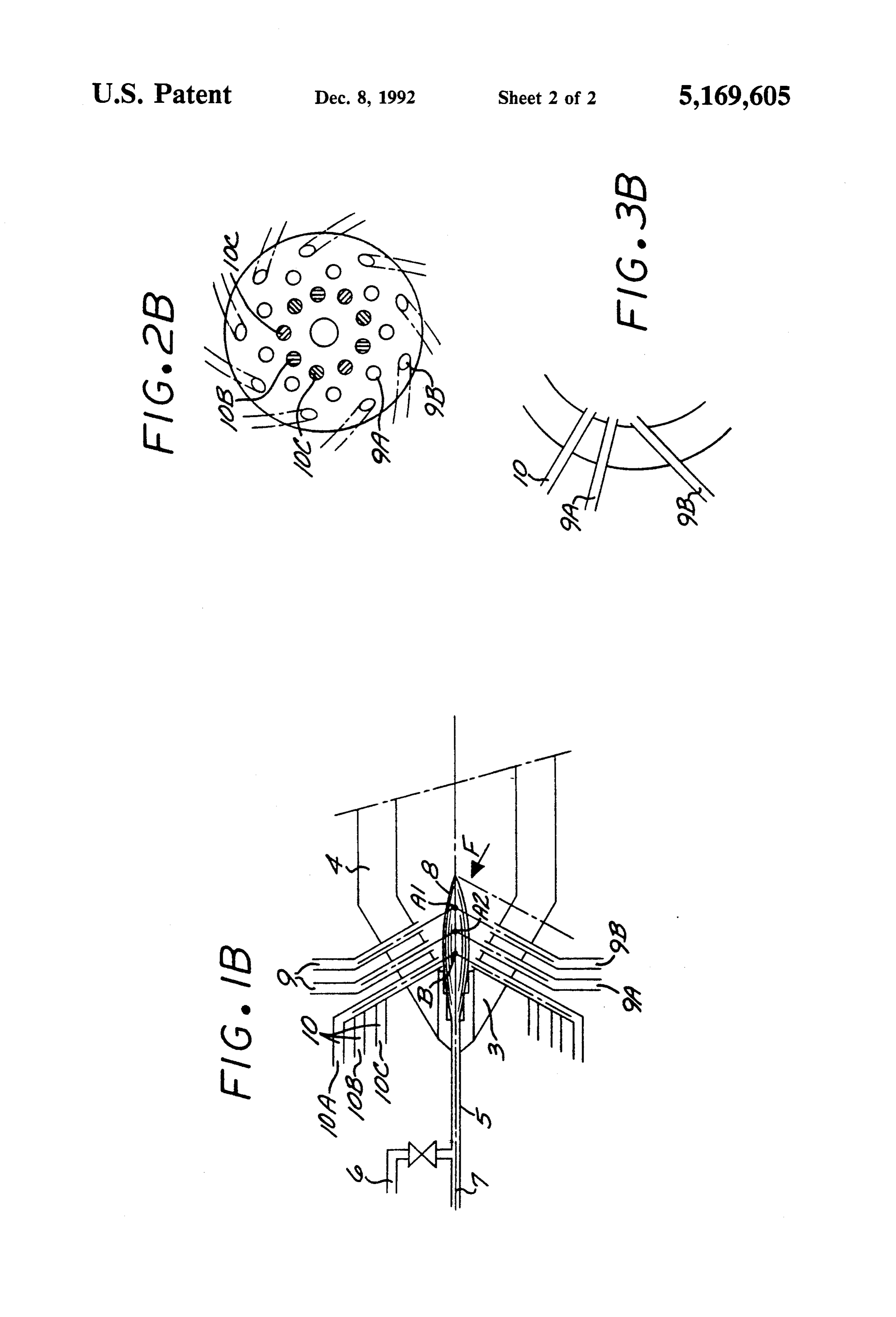
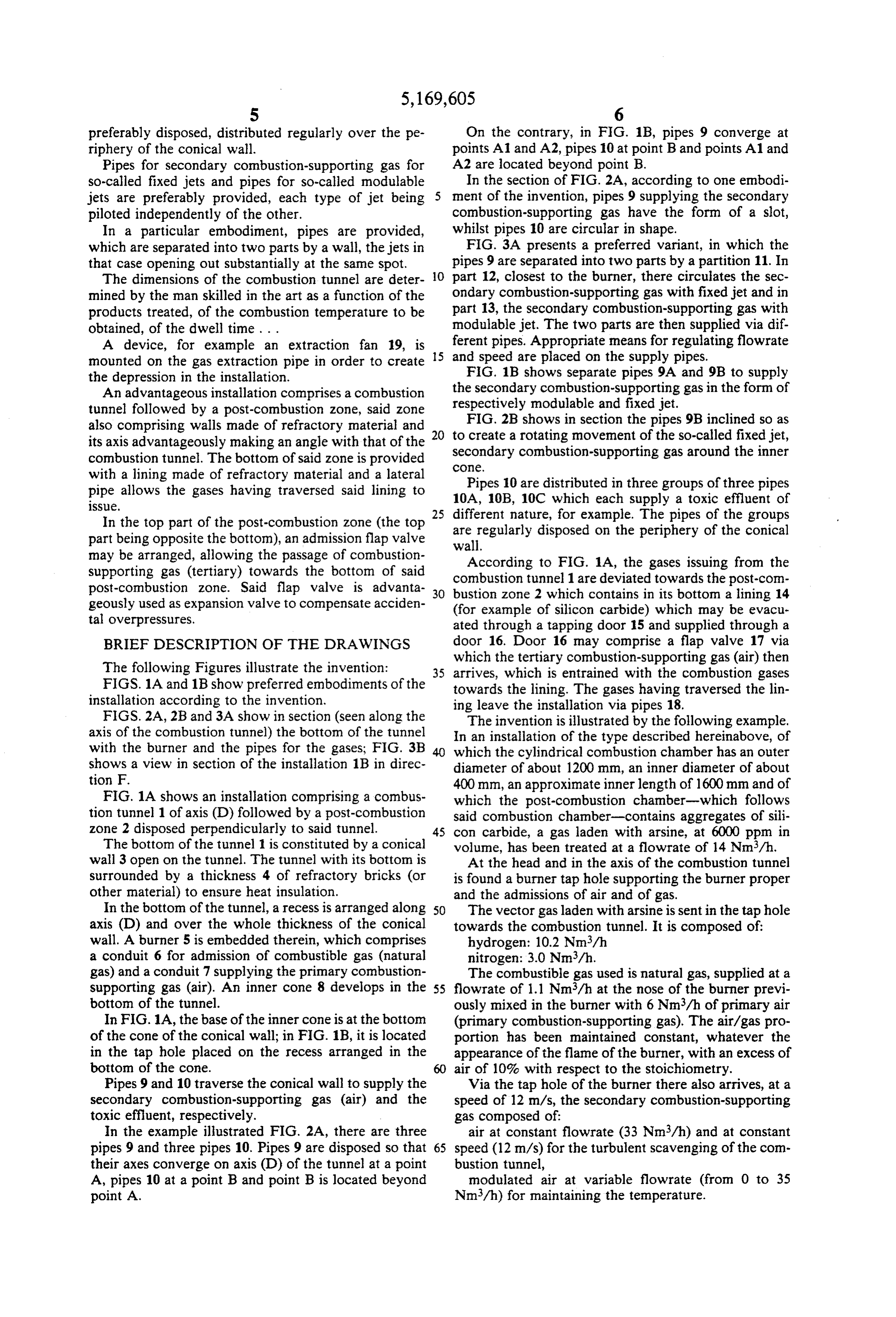
preferably disposed, distributed regularly over the pe On the contrary, in FIG. 1B, pipes 9 converge at riphery of the conical wall. points A1 and A2, pipes 10 at point B and points A1 and Pipes for secondary combustion-supporting gas for A2 are located beyond point B.
so-called fixed jets and pipes for so-called modulable In the section of FIG. 2A, according to one embodi jets are preferably provided, each type of jet being ment of the invention, pipes 9 supplying the secondary piloted independently of the other. combustion-supporting gas have the form of a slot, In a particular embodiment, pipes are provided, whilst pipes 10 are circular in shape. which are separated into two parts by a wall, the jets in FIG. 3A presents a preferred variant, in which the that case opening out substantially at the same spot. pipes 9 are separated into two parts by a partition 11. In The dimensions of the combustion tunnel are deter O part 12, closest to the burner, there circulates the sec mined by the man skilled in the art as a function of the ondary combustion-supporting gas with fixed jet and in products treated, of the combustion temperature to be part 13, the secondary combustion-supporting gas with obtained, of the dwell time . . . modulable jet. The two parts are then supplied via dif A device, for example an extraction fan 19, is 15 and ferent pipes. Appropriate means for regulating flowrate mounted on the gas extraction pipe in order to create speed are placed on the supply pipes. the depression in the installation. FIG. 1B shows separate pipes 9A and 9B to supply An advantageous installation comprises a combustion the secondary combustion-supporting gas in the form of tunnel followed by a post-combustion zone, said zone respectively modulable and fixed jet. also comprising walls made of refractory material and 20 FIG. 2B shows in section the pipes 9B inclined so as its axis advantageously making an angle with that of the to create a rotating movement of the so-called fixedjet, secondary combustion-supporting gas around the inner combustion tunnel. The bottom of said zone is provided cOne, with a lining made of refractory material and a lateral Pipes 10 are distributed in three groups of three pipes pipe allows the gases having traversed said lining to 10A, 10B, 10C which each supply a toxic effluent of issue.
In the top part of the post-combustion zone (the top 25 different are nature, for example. The pipes of the groups regularly disposed on the periphery of the conical part being opposite the bottom), an admission flap valve wall.
may be arranged, allowing the passage of combustion According to FIG. 1A, the gases issuing from the supporting gas (tertiary) towards the bottom of said combustion post-combustion zone. Said flap valve is advanta bustion zonetunnel 1 are deviated towards the post-con geously used as expansion valve to compensate acciden (for example of siliconcontains 2 which in its bottom a lining 14 carbide) which may be evacu tal overpressures. ated through a tapping door 5 and supplied through a BRIEF DESCRIPTION OF THE DRAWINGS door 16. Door 16 may comprise a flap valve 17 via which the tertiary combustion-supporting gas (air) then
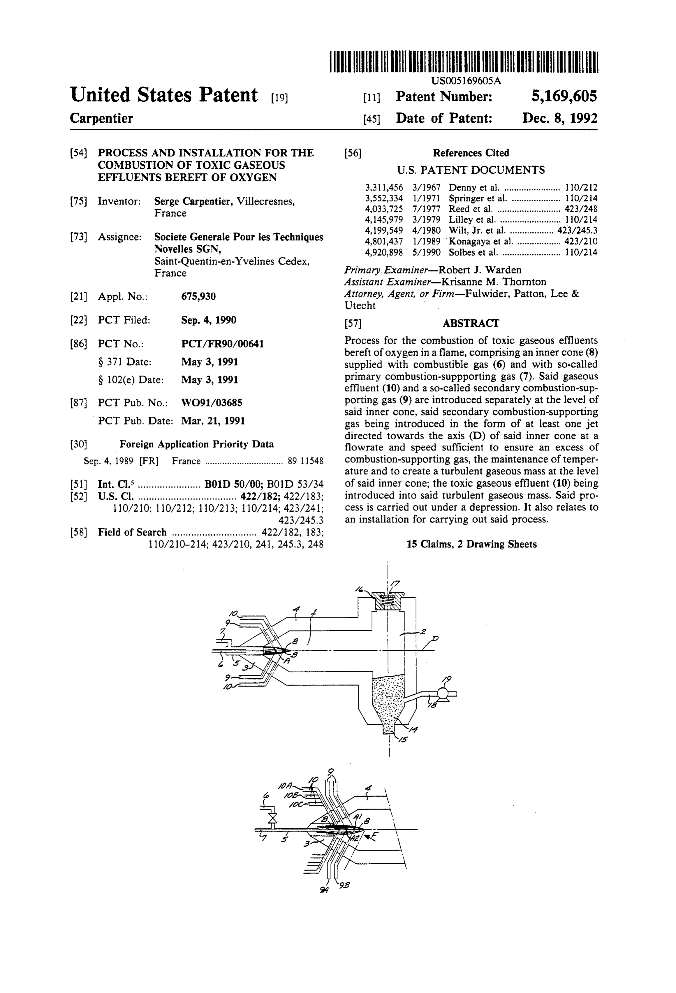
The following Figures illustrate the invention: 35 arrives, which is entrained with the combustion gases FIGS. 1A and 1B show preferred embodiments of the towards the lining. The gases having traversed the lin installation according to the invention. ing leave the installation via pipes 18. FIGS. 2A, 2B and 3A show in section (seen along the The invention is illustrated by the following example. axis of the combustion tunnel) the bottom of the tunnel In an installation of the type described hereinabove, of with the burner and the pipes for the gases; FIG. 3B which the cylindrical combustion chamber has an outer shows a view in section of the installation 1B in direc diameter of about 1200 mm, an inner diameter of about tion F. 400mm, an approximate inner length of 1600mm and of FIG. 1A shows an installation comprising a combus which the post-combustion chamber-which follows tion tunnel 1 of axis (D) followed by a post-combustion said combustion chamber-contains aggregates of sili zone 2 disposed perpendicularly to said tunnel. 45 con carbide, a gas laden with arsine, at 6000 ppm in The bottom of the tunnel 1 is constituted by a conical volume, has been treated at a flowrate of 14 Nm/h. wall 3 open on the tunnel. The tunnel with its bottom is At the head and in the axis of the combustion tunnel surrounded by a thickness 4 of refractory bricks (or is found a burner tap hole supporting the burner proper other material) to ensure heat insulation. and the admissions of air and of gas. In the bottom of the tunnel, a recess is arranged along 50 The vector gas laden with arsine is sent in the tap hole axis (D) and over the whole thickness of the conical towards the combustion tunnel. It is composed of: wall. A burner 5 is embedded therein, which comprises hydrogen: 10.2 Nm3/h a conduit 6 for admission of combustible gas (natural nitrogen: 3.0 Nm/h.
gas) and a conduit 7 supplying the primary combustion The combustible gas used is natural gas, supplied at a supporting gas (air). An inner cone 8 develops in the 55 flowrate of 1.1 Nm3/h at the nose of the burner previ bottom of the tunnel. ously mixed in the burner with 6 Nm/h of primary air In FIG. 1A, the base of the inner cone is at the bottom (primary combustion-supporting gas). The air/gas pro of the cone of the conical wall; in FIG. 1B, it is located portion has been maintained constant, whatever the in the tap hole placed on the recess arranged in the appearance of the flame of the burner, with an excess of bottom of the cone. air of 10% with respect to the stoichiometry. Pipes 9 and 10 traverse the conical wall to supply the Via the tap hole of the burner there also arrives, at a secondary combustion-supporting gas (air) and the speed of 12 m/s, the secondary combustion-supporting toxic effluent, respectively. gas composed of:
In the example illustrated FIG. 2A, there are three air at constant flowrate (33 Nm/h) and at constant pipes 9 and three pipes 10. Pipes 9 are disposed so that 65 speed (12 m/s) for the turbulent scavenging of the com their axes converge on axis (D) of the tunnel at a point bustion tunnel,
A, pipes 10 at a point B and point B is located beyond modulated air at variable flowrate (from 0 to 35 point A. Nm/h) for maintaining the temperature.
Page 7
The depression or subambient pressure in the tunnel table jet is varied as a function of the temperature within is 5 mbar. the combustion zone.
The temperature measured before the lining of silicon 5. Process of claim 14 further comprising the step of carbide is 1000 C. The volume of the fumes at this conducting gases issuing from said combustion Zone temperature is 90 Nm3/h. into a post-combustion zone. Said fumes are then cooled from 1000 C. to 700° C. 6. Process of claim 5 wherein said combustion zone in a heat exchanger then undergo a dilution, by ambient and said post-combustion zone are maintained at a pres air, by a factor 4 (325 Nm3/h) to be taken down to a sure of from 50-600 Pa.
temperature of 100-120° C. before a filtration of very 7. Process of claim 5 further comprising the step of high efficiency (to stop 99.99% of the particles of the O introducing a tertiary oxidizer gas into said gases issuing order of 0.3 um) aiming at retaining the solid arsenous from said combustion zone so as to maintain an excess of acid formed, before rejection in the chimney stack. oxidizer gas in said post combustion zone. At that level, the load of arsine is now only 0.5 ppm 8. Process of claim 5 wherein a temperature of be in volume. The purification yield ensured by the instal tween 900 and 1200° C. is maintained in said post con lation is therefore 99.966%, greater than the 99.95% 15 bustion zone.
required (after having taken into account the dilution at 9. Process of claim 18 wherein a temperature of 1000 cooling). C. is maintained in said post-combustion zone. In addition, the composition of the fumes in the chim 10. Process of claim 1 wherein said toxic gaseous ney stack was approximately as follows: effluent includes at least one constituent selected from nitrogen: 80.0% 20 the group consisting of silane, B, P, As, Te, Se, Cl, and
water (steam): 1.5% 11. Apparatus for the combustion of toxic gaseous carbon dioxide gas: 0.5% effluents bereft of oxygen, comprising: Such an installation is particularly well adapted to the a combustion tunnel oriented along a longitudinal purification of the gases issuing from the electronic 25 axis and terminating in a conically walled end; industry: not only there is virtually complete combus a burner, situated in said conically walled end and tion of the toxic combustible elements, but the forma operative to project a flame of burning fuel and tion of nitrogen oxides or other toxic gases is avoided. primary oxidizer gas into said tunnel along said I claim: axis;
1. Process for the combustion of a toxic gaseous efflu 30 means for injecting secondary oxidizer gas into said ent bereft of oxygen, comprising the steps of: flame adjacent the burner so as to maintain turbu projecting a flame, burning a mixture of a fuel and a lence therein;
primary oxidizer gas, into a combustion zone; means for injecting said gaseous effluents into said maintaining said combustion Zone at subambient pres turbulent flame adjacent the burner; and sure; 35 means for maintaining subambient pressure within injecting into said flame a secondary oxidizer gas in a said combustion tunnel. manner and at a flowrate and velocity sufficient so 12. Apparatus for claim 11 wherein said means for as to create a turbulent gaseous mass, to maintain injecting secondary oxidizer gas into said flame com an excess of oxidizer gas and to maintain a prese prises slots disposed in said conically walled end. lected temperature; and 40 13. Apparatus of claim 11 wherein said means for introducing said toxic gaseous effluent into said tur injecting secondary oxidizer gas into said flame com bulent gaseous mass of said flame. prises at least one fixed jet and one modulatable jet. 2. Process of claim 1 wherein said combustion zone is 14. Apparatus of claim 11 further comprising a post maintained at a pressure of from 50 to 600 Pa. combustion zone arranged along an axis perpendicular 3. Process of claim 1 wherein said secondary oxidizer 45 to said longitudinal axis, said post-combustion zone gas is injected into said flame via a fixed jet delivering being provided at one end with a lining of refractory secondary oxidizer gas at a constant flowrate and veloc materials.
ity and a modulatable jet delivering secondary oxidizer 15. Apparatus of claim 14 further comprising a flap gas at a variable flowrate and velocity. valve disposed at said post-combustion zone's opposite 4. Process of claim 3 wherein the flowrate and veloc 50 end.
ity of secondary oxidizer gas delivered by said modula k
Page 8
UNITED STATES PATENT AND TRADEMARK OFFICE
CERTIFICATE OF CORRECTION
INVENTOR(S) : Serge Carpentier it is certified that error appears in the above-indentified patent and that said Letters Patent is hereby Corrected as shown below:
Column 8, line l, claim 5, delete 14) insert ----. Column 8 line l, claim 9, delete l8 insert --8--.
Signed and Sealed this
Twenty-sixth Day of October, 1993
BRUCE LEHMAN
Attesting Officer Commissioner of Patents and Trademarks
Provenance
- Collection
- Cited prior art
- Original PDF
- patentimages.storage.googleapis.com →
- Filed
- 1990-09-04
- Pages
- 8
- Method
- pdftotext (the PDF's own text layer) + pdftoppm 300dpi page scans
- Source
- Google Patents bibliographic record
- Granted
- 1992-12-08
- Inventors
- Serge Carpentier; Societe Generale pour les Techniques Nouvelles SA SGN
- Transcribed from
- patentimages.storage.googleapis.com →