patent · US4680008
High temperature furnace for integrated circuit manufacture
14 July 1987
Page 1 — bibliographic record
United States Patent (19) 11) Patent Number: 4,680,008 Rioux (45) Date of Patent: Jul. 14, 1987 (54) HIGH TEMPERATURE FURNACE FOR 3,917,442 11/1975 Zagoroff ............................. 432/222 INTEGRATED CIRCUIT MANUFACTURE 4,060,379 11/1977 Lattaye et al. ...................... 432/179
75) Inventor: Brian A. Rioux, Kanata, Canada 4,457,704 7/1984 Sommers et al. ................... 432/222 4,508,669 4/1985 Iwai et al. ............................. 432/72 73) Assignee: Northern Telecom Limited, Montreal,
Canada Primary Examiner-Henry C. Yuen
Attorney, Agent, or Firm-John E. Mowle
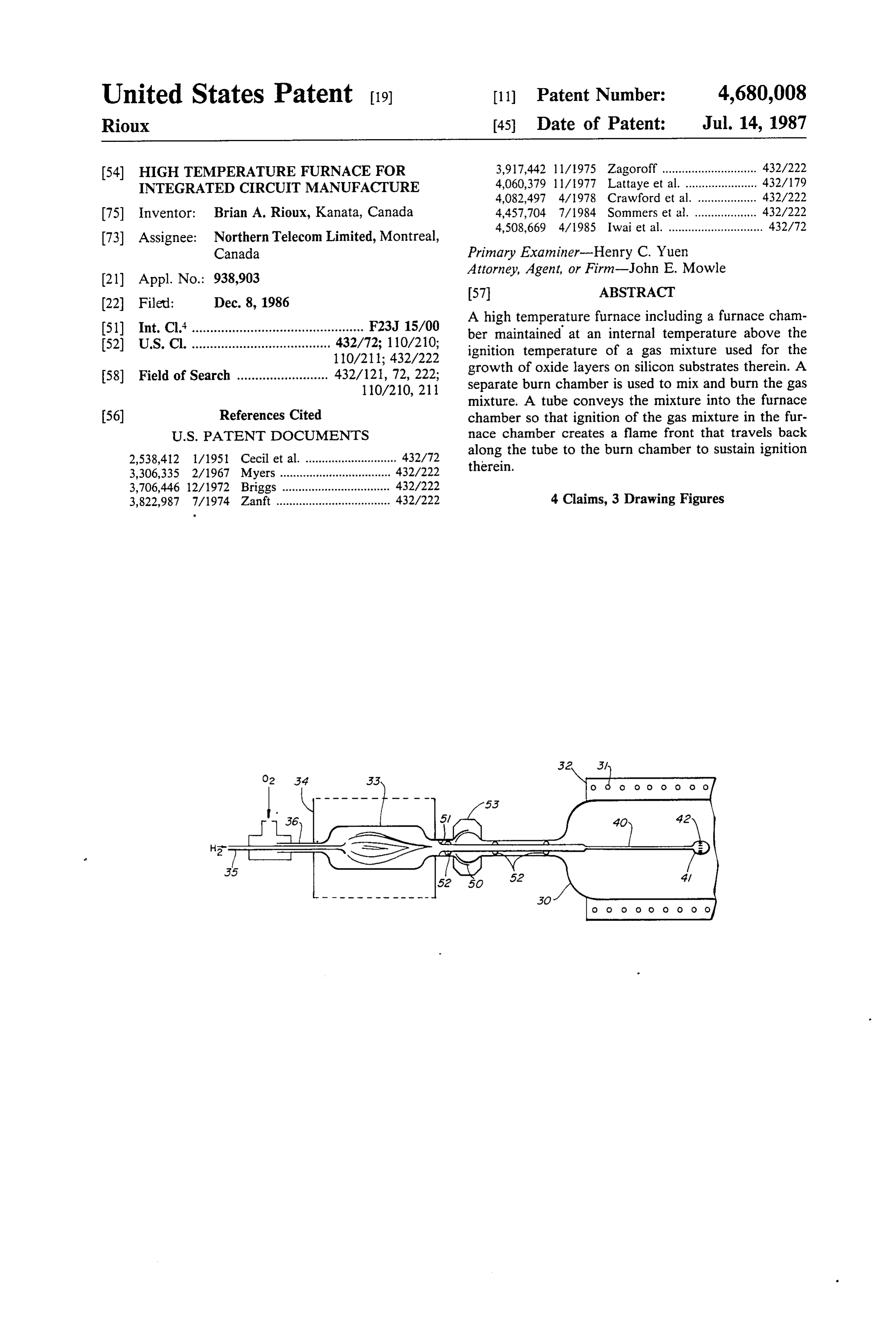
A high temperature furnace including a furnace cham 51) Int. Cl. ............................................... F23J 15/00 ber maintained at an internal temperature above the (52) U.S. Cl. ...................................... 432/72; 110/210; ignition temperature of a gas mixture used for the 110/211; 432/222 growth of oxide layers on silicon substrates therein. A 58) Field of Search ......................... 432/121, 72, 222; separate burn chamber is used to mix and burn the gas
mixture. A tube conveys the mixture into the furnace 56) References Cited chamber so that ignition of the gas mixture in the fur
2,538,412 1/1951 Cecil et al. ............................ 432/72 along the tube to the burn chamber to sustain ignition 3,306,335 2/1967 Myers .... ... 432/222 therein.
3,706,446 12/1972 Briggs ... ... 432/222 3,822,987 7/1974 Zanft ................................... 432/222 4 Claims, 3 Drawing Figures
Page 2
Drawing sheet — no readable text.
Page 3
Drawing sheet — no readable text.
Page 4
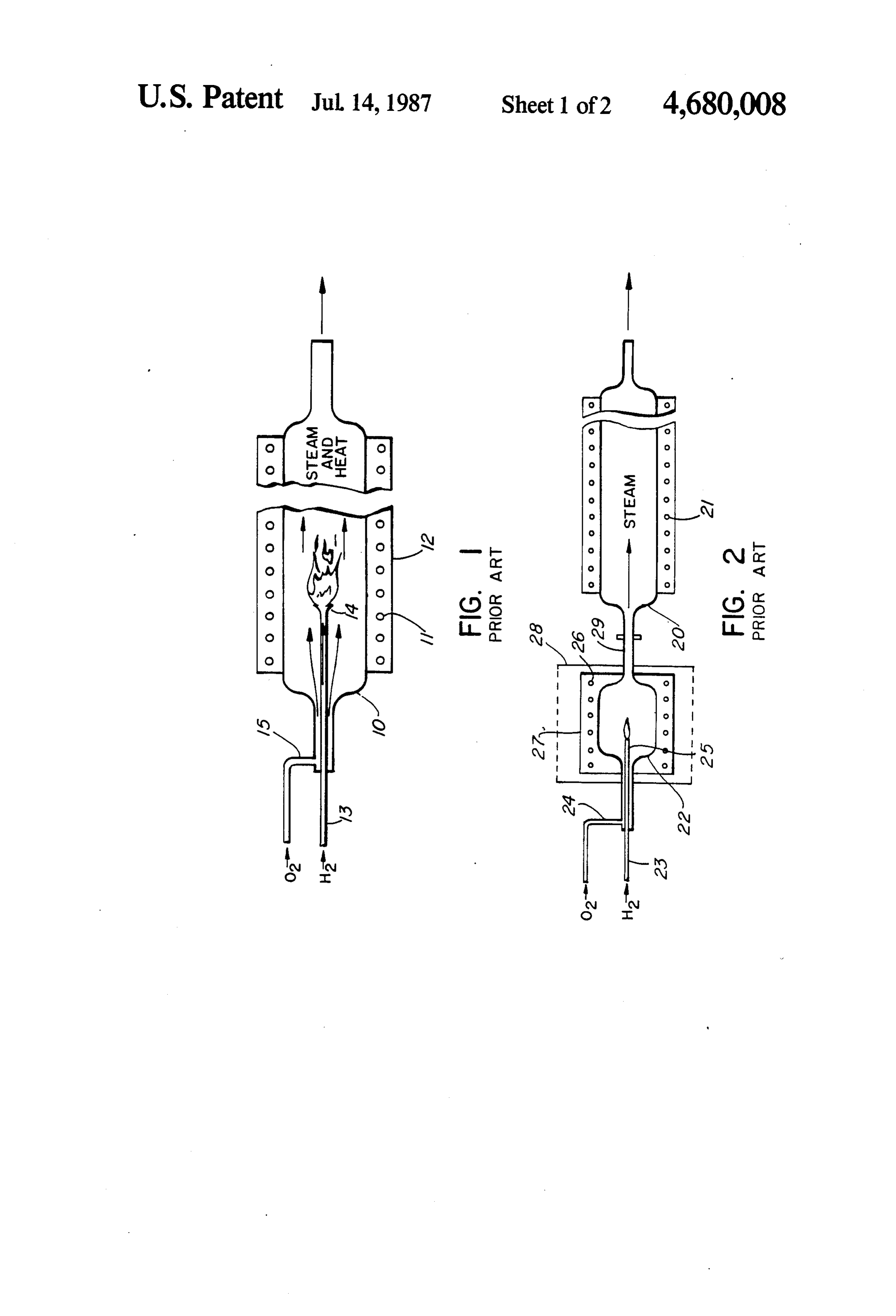
nace of the present invention will now be described
HIGH TEMPERATURE FURNACE FOR with reference to the accompanying drawings in which: INTEGRATED CIRCUIT MANUFACTURE FIG. 1 is an example of a prior art high temperature furnace having a standard hydrogen burner-injector
This invention relates to a high temperature furnace 5 tube located in the furnace chamber; and more particularly to an improved pyrogenic hydro FIG. 2 is an example of a prior art high temperature gen burner which may be utilized to grow oxide layers furnace having an external burn chamber with its own on silicon substrates in such a furnace ignition source;
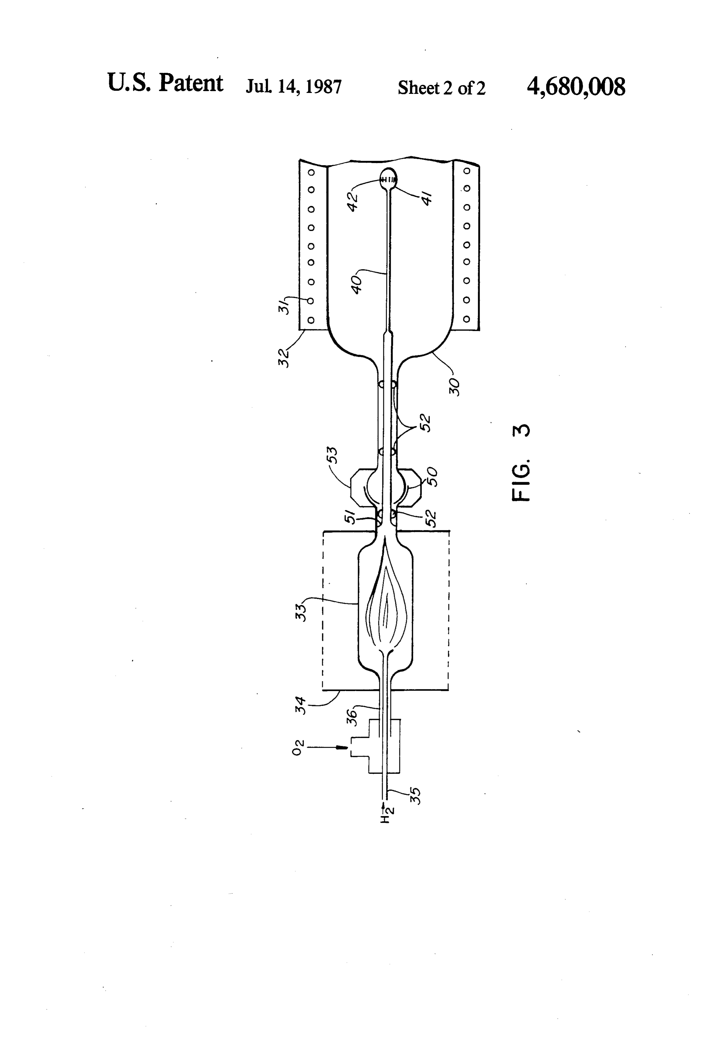
FIG. 3 is a high temperature furnace in accordance
BACKGROUND OF THE INVENTION 10 with the present invention having an external burn In the manufacture of integrated circuits a number of chamber which eliminates the need for a separate igni high temperature processes are employed to grow oxide tion source and control.
layers on the silicon substrates. These take place in DESCRIPTION OF THE PREFERRED quartz lined high temperature furnaces. Oxidations EMBODIMENT AND THE PRIOR ART which must be grown quickly are usually preformed in 15 a steam ambient which is created by burning hydrogen high Referring to FIG. 1, there is illustrated a prior art in oxygen within the furnace itself. This can lead to hydrogen temperature furnace which utilizes an internal temperature control instabilities since burning hydro tional quartz burner. The furnace comprises a conven gen generates appreciable amounts of heat. Pyrogenic 20 rounded by anlined furnace chamber or tube 10 sur heating is especially bad in large diameter furnaces stainless steel protectiveheating electric element 11 encased in a cover 12. The heating element which must be purged with high gas flows to prevent 11 maintains the temperature of the furnace chamber 10 atmospheric backsteaming. at a minimum of about 650 C. which is above the igni One solution to this dilemma has been to locate the tion temperature of a hydrogen-oxygen gas mixture. hydrogen burner outside of the furnace tube which 25 Conventional heating and safety controls (not shown) eliminates the unwanted heat from the furnace. A num ber of these furnaces already exist in the industry but are utilized to control the heating element 11. their complexity and cost have led to limited accep a silicon substrate,steam
To provide the which is used to grow oxide on hydrogen (H2) is introduced via a tance. The major reason is that such burners utilize a quartz tube 13 which has a flared end 14 for evenly separate burn chamber which has its own ignition sys 30 dispersing the hydrogen gas into the furnace chamber tem with temperature and safety controls. 10. Concurrently, oxygen (O2) is introduced in a con STATEMENT OF THE INVENTION centric quartz tube 15 surrounding the tube 13, and ignites the hydrogen in the heated chamber 10 to pro
The present invention overcomes the drawbacks of duce steam from the reaction 2H2--O2 = 2 H2O. This prior furnaces by utilizing a separate furnace chamber 35 pyrogenic reaction generates a good deal of heat in the and burn chamber as described above. However the furnace chamber 10 which is difficult to control, and as burn chamber is connected to the furnace chamber in stated earlier, is of particular concern in new, larger such a way that the heat in the furnace chamber can be diameter furnaces which must be purged with high gas utilized to provide ignition for the gas mixture in the flows to prevent atmospheric backsteaming. burn chamber thereby eliminating the duplicate heating 40 This heat problem has been alleviated by the develop elements and controls. This provides both a consider ment of a high temperature furnace in which the reac able cost saving as well as a reduction in the complexity tion takes place outside the furnace chamber in a sepa of the overall furnace. rate compartment as illustrated in the prior art furnace Thus, in accordance with the present invention there of FIG. 2. Here a quartz lined furnace chamber 20 with is provided a high temperature furnace for the growth 45 its controlled heating element 21 is coupled to a quartz of oxide layers on silicate substrates and the like, in lined burn chamber 22 in which the hydrogen and oxy which the furnace comprises a furnace chamber and a gen gases are introduced by tubes 23 and 24 respec heating means for maintaining the internal temperature tively, in a similar manner to that illustrated in the prior of the chamber at a temperature greater than the igni art furnace of FIG. 1. However because the burn cham tion temperature of a hydrogen-oxygen gas mixture. 50 ber 22 is much smaller and there is no need to have even The high temperature furnace also includes a burn dispersion of the heat a much simpler injector nozzle 25 chamber external to the furnace chamber for mixing can be utilized on the end of the tube 23. and burning the gas mixture. It also includes a tube for To provide ignition for the hydrogen-oxygen gas conveying the gas mixture from the burn chamber to mixture, the burn chamber 22 also includes a tempera the furnace chamber. To ensure proper combustion of 55 ture controlled heating element 26 encased in a stainless the gas mixture, the tube protrudes into the furnace steel housing 27 and safety cage 28. Steam from the chamber a sufficient distance that the ambient tempera pyrogenic reaction is coupled through an interconnect ture at the point where the gas mixture is expelled from ing tube 29 to the furnace chamber 20. However much the tube, is greater than the ignition temperature. As a of the heat escapes from around the burn chamber 22 result, the gas mixture upon ignition in the furnace 60 through the safety cage 28 so as to minimize pyrogenic chamber creates a flame front that travels back along heating in the furnace chamber 20. Thus, while this the tube into the burn chamber to sustain ignition prior art structure provides good temperature control in therein. the furnace chamber 20, it is considerably more costly
BRIEF DESCRIPTION OF THE FORMAL
particularly because a separate controlled heating ele 65 ment 26 is required for the burn chamber 22.
DRAWINGS One problem with this structure is that if the heating Examples of prior art high temperature furnaces and element 26 was to fail and the unignited hydrogen-oxy an example embodiment of the high temperature fur gen gas mixture was allowed to enter the furnace cham
Page 5
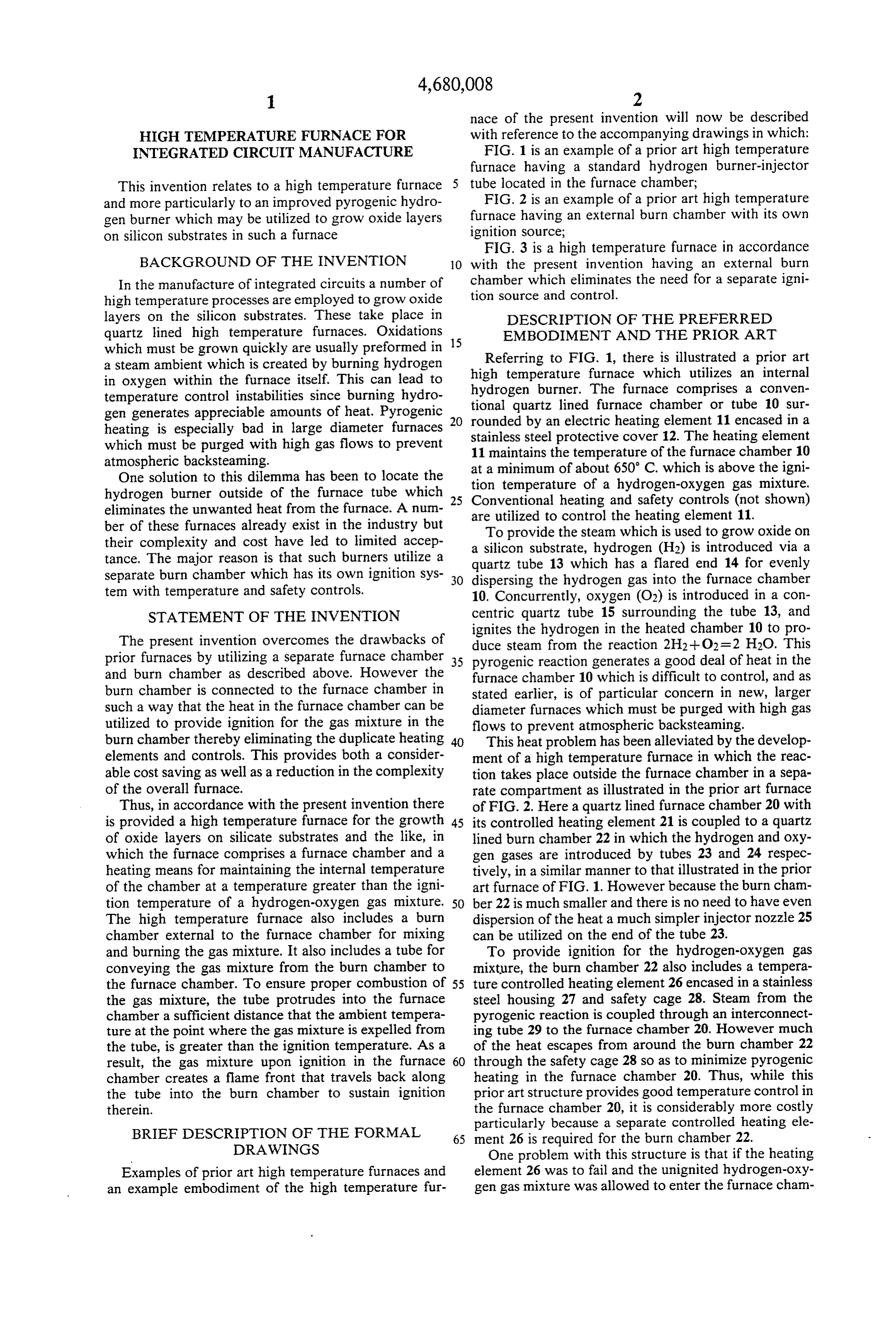
ber 20, it would initially be widely dispersed so that it long as the mix ratio is correct. Higher flows will result would not immediately ignite even though the tempera in The overheating of the burn chamber 33. interconnection of the burn chamber 33 and the ture in the furnace chamber 20 is above the ignition point of the gas mixture. After a considerable amount of 5 furnace injector chamber 30 is a ball-and-socket joint 50. The tube 40 is flared at its other end 51 and clamped the gas mixture has accumulated in the furnace chamber between the ball-and-socket joint 50 by a stainless steel 20 it would ignite with a fairly violent reaction causing clamp 53. Small protrusions 52 on the sides of the tube damage to the quartz ware in one or both of the cham bers 20 and 22. Thus with this prior art structure, addi 40 the ensure a tight fit between the tube 40 and the end of furnace chamber 30. The slots 42 are disposed so as tional safety controls have to be installed to ensure that 10 to direct the steam back towards the end where the tube the gas supply is not turned on before the minimum 40 protrudes into the chamber 30 so as to ensure that the ignition temperature of the burn chamber 22 is reached. whole chamber 30 is purged.
Referring to FIG. 3, the high temperature furnace of What is claimed is:
the present invention comprises a quartz lined furnace 1. A high temperature furnace for the growth of chamber 30 surrounded by a controlled heating element 15 oxide layers on silicon substrates and the like, the fur 31 encased in a stainless steel housing 32 as in both the nace comprising:
prior art furnaces. In addition, it includes a quartz lined a furnace chamber;
burn chamber 33 encased in a stainless steel safety cage heating means for maintaining the internal tempera 34, which is fed by hydrogen and oxygen gas through ture of the chamber at a temperature greater than quartz tubes 35 and 36 respectively. The burn chamber 20 a burn the ignition temperature of a gas mixture; and 33 is similar to that shown in the prior art chamber 22 in chamber external to the furnace chamber for FIG. 2 but differs in that it does not contain any heating mixing and burning said gas mixture therein; element or temperature and safety controls. In addition, characterized by:
the output of the hydrogen-oxygen gas mixture from 25 a tube for conveying the gas' mixture from the burn chamber to the furnace chamber;
the burn chamber 33 is conveyed to the furnace cham one end of the tube protruding into the furnace cham ber 30 via an ignition injector tube 40, which protrudes ber a sufficient distance that the ambient tempera about 25 cm inside the furnace chamber 30. A bulbous ture, contiguous an opening in the tube which ex end 41 of the protruding tube 40 has a plurality of pe pels the gas mixture into the furnace chamber, is ripheral slots 42 which evenly distribute the gas mixture 30 greater than said ignition temperature, resulting in in a confined or concentrated area. Because these slots ignition of the gas mixture in the furnace chamber 42 are well spaced from the walls of the furnace cham which creates a flame front that travels back along ber 30, the ambient temperature of the bulbous end 41 of the tube into the burn chamber, to initiate and the tube 40 is well above the minimum ignition tempera sustain ignition ture for the hydrogen-oxygen gas mixture. As a result of 35 the burn chamber and the furnace chamber are joined this gas concentration and the temperature of the cham at a mating ball-and-socket joint; and ber 30, the initial ignition of the mixture takes place the other end of the tube is flared and clamped be very rapidly once the gas mixture starts to flow along tween the mating ball-and-socket joint. the tube 40 where the temperature has reached the which 2. A high temperature furnace as defined in claim 1 in ignition point of about 650 degrees C. This creates a eral openings said one end of the tube has a plurality of periph flame front that travels back along the tube 40 into the that the gas mixture orthogonal to the length of the tube, so burn chamber 33 to ignite and sustain ignition therein the tube protrudes therein. purges the furnace chamber where without the need for heating elements or other ignition 3. A high temperature furnace as defined in claim 2 in sources within this chamber 33. Even though the vol 45 which:
ume of the burn chamber 33 is much smaller than that of the gas mixture, containing hydrogen and oxygen, the furnace chamber 30, a small explosion will still take produces steam when ignited, and the heating place. The cross-sectional area of the tube 40 and hence means maintains the furnace chamber at a tempera its diameter is selected so as to dampen any pressure ture greater than about 650 degrees centigrade. front resulting from ignition of the gas mixture in the 50 4. A high temperature furnace as defined in claim 3 in burn chamber 33 thereby minimizing any possible dam which:
age to the furnace. A typical internal diameter for the the cross-sectional area of the tube is selected so as to tube is 6 mm. Typical gas flows for such a chamber are dampen any pressure front resulting from ignition up to 4.5 l/min. for H2 and 3.0 l/min. for O2 with a 3:2 of the gas mixturek ink the burn
chamber.
ratio being maintained. Lower flows are acceptable as 55
Provenance
- Collection
- Cited prior art
- Original PDF
- patentimages.storage.googleapis.com →
- Filed
- 1986-12-08
- Pages
- 5
- Method
- pdftotext (the PDF's own text layer) + pdftoppm 300dpi page scans
- Source
- Google Patents bibliographic record
- Granted
- 1987-07-14
- Inventors
- Brian A. Rioux; Northern Telecom Ltd
- Transcribed from
- patentimages.storage.googleapis.com →