patent · US5140966
Carburetor for an internal combustion engine
25 August 1992
Page 1 — bibliographic record
United States Patent (19) 11) Patent Number: 5,140,966 Wong (45) Date of Patent: Aug. 25, 1992
(54) CARBURETOR FOR AN INTERNAL
COMBUSTON ENGINE
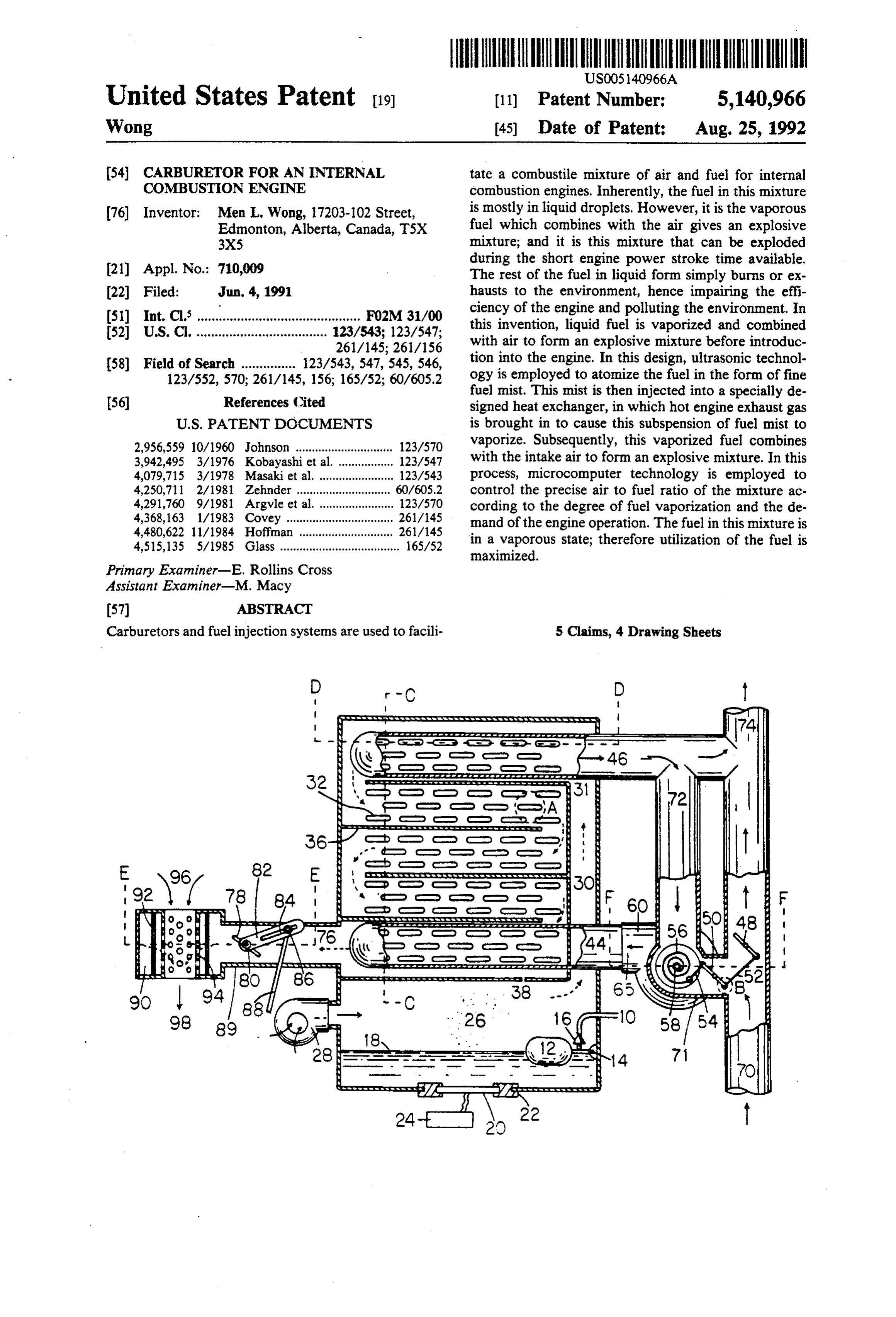
tate a combustile mixture of air and fuel for internal combustion engines. Inherently, the fuel in this mixture (76) Inventor: Men L. Wong, 17203-102 Street, is mostly in liquid droplets. However, it is the vaporous Edmonton, Alberta, Canada, TSX fuel which combines with the air gives an explosive 3X5 mixture; and it is this mixture that can be exploded (21) Appl. No.: 710,009 during the short engine power stroke time available. The rest of the fuel in liquid form simply burns or ex (22 Filed: Jun. 4, 1991 hausts to the environment, hence impairing the effi 51) Int. Cl. ............................................. F02M 31/00 ciency of the engine and polluting the environment. In 52 U.S. Cl. .................................... 123/543; 123/547; this invention, liquid fuel is vaporized and combined 261/145; 261/156 with air to form an explosive mixture before introduc (58) Field of Search ............... 123/543, 547, 545, 546, tion into the engine. In this design, ultrasonic technol 123/552, 570; 261/145, 156; 165/52; 60/605.2 ogy is employed to atomize the fuel in the form of fine fuel mist. This mist is then injected into a specially de (56) References (ited signed heat exchanger, in which hot engine exhaust gas
2,956,559 10/1960 Johnson .............. ... 123/570 vaporize. Subsequently, this vaporized fuel combines 3,942,495 3/1976 Kobayashi et al. . ... 123/547 with the intake air to form an explosive mixture. In this 4,079,715 3/1978 Masaki et al. ........... ... 123/543 process, microcomputer technology is employed to 4,250,711 2/1981 Zehnder ............................. 60/605.2 control the precise air to fuel ratio of the mixture ac 4,291,760 9/1981 Argvle et al. ....................... 123/570 cording to the degree of fuel vaporization and the de 4,368,163 1/1983 Covey ................. ... 261/45 mand of the engine operation. The fuel in this mixture is 4,480,622 11/1984 Hoffman ......... ... 26/145 4,515,135 5/1985 Glass ..................................... 165/52 in a vaporous state; therefore utilization of the fuel is maximized.
Primary Examiner-E. Rollins Cross
Assistant Examiner-M. Macy
Carburetors and fuel injection systems are used to facili 5 Claims, 4 Drawing Sheets
evasta Rue Yuasarass ava vauhava vav www.vaa vav vs vavaravarara e val
O O o coco
Page 2
Stasaasaas to cd O. O. clo to cro co P to co - - Naadodaddaarded 2 de
A Leesecretc. Cocces. RCECss asFasROeases
OFP OeA
to D - O - - - - - - - a-- Ou - - - unu Oru - - - - - - t Otb o O O. O. O.
cleced
Page 3
Drawing sheet — no readable text.
Page 4
Drawing sheet — no readable text.
Page 5
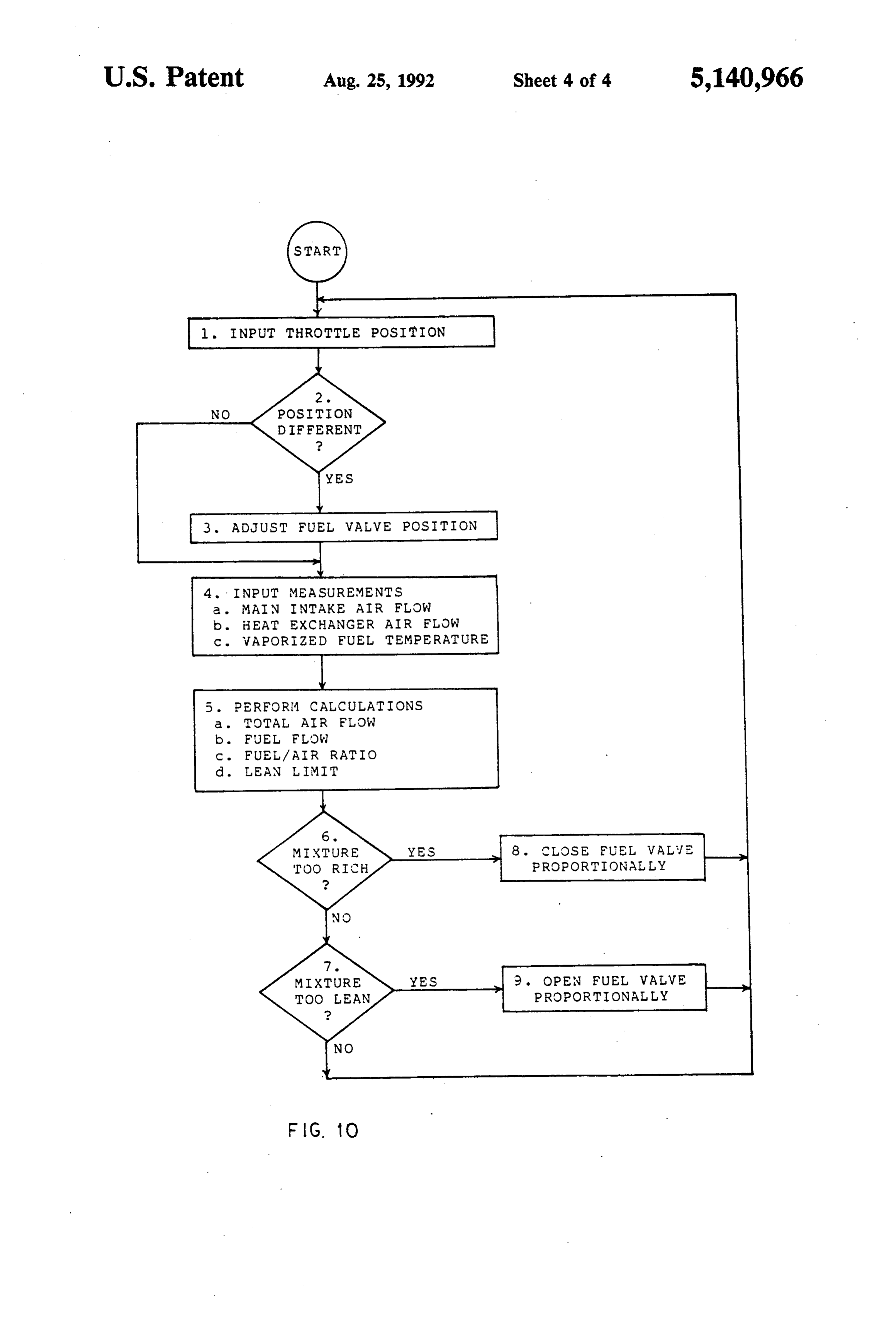
l. INPUT THROTTLE POSITION
POSITON
DIFFERENT
3 ADJUST FUEL WALWE POSITION
4 - INPUT MEASUREMENTS
a. MAN INTAKE AIR FLOW b. HEAT EXCHANGER AIR FLW c. WAPORIZED FUEL TEMPERATURE
5. PERFORM CAL CULATIONS
a TOTAL AIR FLOW b. FUEL FLOW c. FUEL / AIR RATIO
LEAN LIMIT
MIXTURE 8. CLOSE FUEL VALIE
TOO LEAN PROPORTIONALLY
FIG. O
Page 6
come in contact with the ultrasonic transducer. Vibrat
CARBURETOR FOR AN INTERNAL ing at high frequency, the transducer breaks the fuel COMBUSTION ENGINE into finer droplets. However, these finer droplets re main mostly still in liquid form. It is also known that air
BACKGROUND OF THE INVENTION 5 is a poor medium for ultrasonic wave transmission, In carburetors, the intake air breaks up the liquid fuel therefore ultrasonic wave energy is substantially re into droplets. Together the air and the atomized fuel duced to have little effect on the droplets which are not form the combustible mixture for internal combustion in immediate contact with this ultrasonic transducer. engines. Unfortunately, there is only the small area O Another approach is a stand alone carburetor which around each droplet of liquid fuel that is vaporized, consists of a few basic modules for conditioning the leaving the rest still in liquid form when this mixture fuel. This is the approach this invention is based on. enters the engine. It is the vaporous fuel combined with Commonly, this design has four basic modules, they are the air which gives an explosive mixture; and it is this a fuel atomization chamber, a heat exchanger, heat mixture that can be exploded during the short engine exchanger temperature control apparatus and fuel me power stroke time available. The remaining portion of tering mechanism. Earlier attempts usually employme fuel, still in liquid form, simply burns or exhausts to the chanical spray nozzle for fuel atomization with bulky environment; hence impairing the efficiency of the en heat exchanger, simple heat exchanger temperature gine and polluting the environment. This situation is control and fuel metering mechanisms. more apparent for low speed and low load operations One of the main problems encountered in vaporiza when the intake air velocity is too low to effectively 20 tion carburetor is gumming. Gumming occurs when break up the fuel droplets. The fuel injection systems, high molecular weight components of the fuel, referred employed for some internal combustion engines today, to as high ends of the hydrocarbon, cannot vaporize and alleviate the problem to some extent by injecting the liquid fuel directly into the intake air stream via a nozzle begin to stick to the heat exchanger surface, in effect. to produce finer droplets and providing a more precise 25 lowering that the efficiency of the heat exchanger to a stage renders this approach impractical. Some designs air/fuel mixture. Unfortunately, even the finer droplets have heater elements submersed in the fuel for fuel remain mostly in liquid form. vaporization. Light ends of the hydrocarbon simply boil Realizing this problem, there were numerous designs off and the high ends remain.
for vaporizing the fuel by inventors in the past and some inevitable in this situation. Obviously, gumming is of them were granted patents. However, the problems 30 The disadvantage of employing mechanical spray for for making this concept practical have not been fully overcome. There have been many attempts to improve fuel atomization is the production of very coarse fuel the vaporization state of the fuel by employing ultra droplets. As these droplets contact the heat exchanger sonic technology and engine exhaust heat for fuel va hot surface, light ends of the hydrocarbon vaporize and porization. In this section, the shortcomings of these 35 cool the hot surface. Subsequently, high ends of the attempts and in particular the problems encountered hydrocarbon cannot vaporize and start to accumulate. with this type of carburetion, namely vaporization car Some designs introduce the amount of atomized fuel buretion, will be outlined. according to the engine demands; controlled by the The most common designs to vaporize the fuel is to engine vacuum or activated by the throttle position. provide an exhaust gas heated, engine coolant heated, Some designs simply rely on the intake air to meter the or electrically heated heat exchanger in between the atomized fuel like the conventional carburetor does. conventional carburetor and the intake manifold. The These type of designs cannot satisfy transient require main disadvantage of this type of designs is the overall ments such as load variations, acceleration or decelera heating of the intake air. This heating tends to promote tion because of the lag effects related to the fuel reach detonation; the uncontrollable ignition of the fuel mix 45 ing the engine from its point of injection. This time ture inside the engine cylinder. Another disadvantage is delay is due to the time it takes for the fuel to pass the reduction of the maximum power output of the through the heat exchanger.
engine. As the intake air temperature increases, the air Vaporization of fuel requires abundant heat. Com mass going into the engine decreases due to the physical monly heat from the engine exhaust is used for this property that at higher air temperatures, the air density SO purpose because this heat is the waste byproduct from is lowered. In effect the maximum power produced by the consumed fuel. Most of the previous designs cannot the fuel and air explosion is lessened. Some of these make use of a large amount of engine exhaust because designs divert a portion of the intake air and fuel into the engine exhaust is too hot to be injected in large the heat exchanger. Subsequently, only a portion of the quantity into the heat exchanger without risk of igniting fuel is vaporized and the majority of the fuel is still in 55 the fuel inside. Realizing this difficulty, some designs liquid form. In engine coolant heated systems, the tem divert only a portion of the engine exhaust into the heat perature of the engine coolant is not high enough for exchanger. Unfortunately, the heat obtained from this fuel vaporization. In electrically heated systems, extra portion of the exhaust is not adequate for thorough fuel batteries may be needed for providing the electrical vaporization. In addition to this, the exhaust gas flow is power to the heat exchanger, and in general extra en relatively slow which is considered to be laminar flow gine power is needed to generate this electricity to be inside the heat exchanger. It is known that laminar flow effective. yields poor heat transfer efficiency. In most cases, a Other attempts involved employing ultrasonic tech large heat exchanger is required for thorough fuel va nology to produce finer droplets. Commonly, an ultra porization.
sonic transducer, which is made of piezoelectric crystal, 65 Depending on the design, the divertion of the exhaust is mounted between the conventional carburetor and gas sometimes creates high engine exhaust back pres the intake manifold. As the intake air and the fuel pass sure. This high exhaust back pressure affects the effi through the ultrasonic transducer, some droplets of fuel ciency of the engine. As the exhaust valve of the engine
Page 7
opens, it is desirable to expell the exhaust gas out of the idly without lowering the surface temperature signifi cylinder as freely as possible. However, if the passage of cantly, therefore the high ends of the hydrocarbon still the exhaust is obstructed to divert the exhaust gas into has the required condition to vaporize eventually. the heat exchanger, the extra engine power would be Hence gumming is not possible. It should be noted, the needed to push the exhaust gas out of the engine cylin amount of atomized fuel is prepared independent of the der. engine demand. The ultrasonic transducer always pro Another problem associated with making the vapori duces adequate atomized fuel for maximum engine op zation carburetor practical is the control of the heat eration, and the vaporized fuel in the heat exchanger is exchanger temperature. The temperature of the engine always maintained in saturated equilibrium. exhaust varies with different operating conditions of the O The heat exchanger is specially designed to provide engine. In particular, the temperature control is fairly efficient vaporization of the fuel and minimize gumming demanding during transient situations such as; load occurence, Baffles are used to divert the fuel droplets to variations, acceleration and deceleration. The tempera travel through the heat exchanger in a zigzag manner ture of the engine exhaust is high enough to ignite the so that the volume of the heat exchanger is used effec fuel, therefore as more engine exhaust is diverted into 15 tively. The fuel droplets and exhaust gas are travelling the heat exchanger, more demands are placed upon the in a counter flow manner so as to maximize the output temperature control mechanism. In addition, as the fuel vapour fuel temperature. The fuel droplets travel from vaporizes, the heat exchanger requires more heat. the top to the bottom and the vaporized fuel is extracted Therefore means have to be provided to control the from the bottom of the heat exchanger. As the fuel temperature of the heat exchanger in response to the 20 droplets travels downwards, the light ends of the hy incoming engine exhaust gas and the effect of the fuel drocarbon vaporize rapidly and some of the high ends vaporization in order to be effective. of the hydrocarbon, not yet vaporized, also travel The fuel prepared by the vaporization carburetor is downwards with the assistance of gravity. As the highly explosive. This ensures a thermodynamic advan heated surface becomes hotter because of the counter tage when this explosive mixture is ignited inside the 25 flow arrangement, the high ends of the hydrocarbon engine cylinder. Proper means have to be designed to eventually vaporize as well. This counter flow design protect this vaporous fuel from igniting in case of back and from-top-to-bottom fuel path are to facilitate more firing of the engine. Backfire occurs in an engine when time and high temperature condition to vaporize the the mixture is too lean, resulting in the time needed to high ends of the hydrocarbon. It should be noted, since complete the combustion being extended well into the 30 high intake air temperature promotes detonation, the air intake cycle. A backfire arrester has to be able to arrest heated is only a small portion of the total intake air. This the fire and at the same time provide non-restrictive small portion of the heated air is used as a carrier for the passage for the vaporous fuel. fuel droplets into the heat exchanger. The main advantage of the vaporization carburetor is In this invention, a pair of unison butterfly valves is the ability to extend the lean limit. The lean limit means 35 employed for the diversion of the engine exhaust gas the maximum air to fuel ratio for the engine without into the heat exchanger. They are designed so that the apparent backfiring, misfiring, detonation or any unde total cross-sectional exhaust area is preserved indepen sirable effect due to lean combustion. The effectiveness dent of the valve positions. This is to ensure the free of fuel saving is the capability of the design to control passage for engine exhaust gas. An air blower is also the precise air to fuel ratio in all operations of the en employed to draw the engine exhaust gas into the heat gine. The previous inventions apparently have not ad exchanger. The combination of these unison valves and dressed this fundamental problem. Although a vapori the air blower effectively divert the engine exhaust gas zation carburetor offers advantages in fuel economy into the heat exchanger without increasing the engine and exhaust emission, making this concept practical is exhaust back pressure. This same air blower is also not an easy process. 45 employed for recirculating the exhaust gas in the heat SUMMARY OF THE INVENTION exchanger. Since the exhaust gas is circulating inside the heat exchanger at high velocity by this air blower,
The objective of this invention is to produce a carbu uniformly high temperature throughout the heat ex retor which can provide fuel in vaporous state and changer is achieved and instead of laminar flow of the combine with air to form an explosive mixture before 50 exhaust gas, turbulent flow is established which contrib introduction into the engine, thereby maximizing the utes higher heat transfer efficiency. As the cooled ex utilization of the fuel during the engine power stroke haust gas of the recirculation line from the outlet of the cycle. This invention consists of five main modules, heat exchanger is combined with the hot engine exhaust they are fuel atomization chamber, heat exchanger, heat gas, more hot engine exhaust gas can be diverted into exchanger temperature control apparatus, backfire ar 55 the heat exchanger without risking igniting the fuel rester and fuel metering mechanism. The unique designs inside, therefore extraction of the waste heat from the of these modules facilitate features that prevent gum engine exhaust can be maximized. With this unique heat ming, provide high efficient heat transfer between en exchanger design and the employment of this circula gine exhaust gas and the fuel, improve heat exchanger tion blower, the heat exchanger size is substantially temperature control reliability and sensitivity, and pro reduced without degrading the degree of fuel vaporiza vide optimum air/fuel mixture for engine comsumption. tion.
In the fuel atomization chamber, ultrasonic wave is A temperature sensitive bimetal actuator, situated in employed to atomize the fuel for its ability to produce the gas streams of the engine exhaust gas and the recir ultra fine fuel droplets. The piezoelectric ultrasonic culation exhaust gas, is employed such that it responds transducer is submersed underneath the fuel for maxi 65 to both the incoming engine exhaust gas temperature mum atomization effect. Because the fuel droplets are and the recirculation exhaust gas temperature. In turns, so fine when they contact the heat exchanger hot sur the bimetal actuator controls the heat exchanger inlet face, the light ends of the hydrocarbon vaporizes rap temperature via a pair of unison butterfly valves. In
Page 8
effect, this temperature control mechanism responds to liquid fuel in the heat exchanger can be thoroughly the combination of the source of the heat and the effect vaporized. The fuel after vaporized is combined with of the vaporization for the control. the main intake air 96 via the vapour fuel metering A specially designed backfire arrester is situated be valve and backfire arrester (item 78 to 94) to form the tween the intake manifold and the heat exchanger to explosive mixture 98 for the engine consumption. A prevent the backfiring of the engine from igniting the specially designed microcomputer control system ( fuel inside the heat exchanger. A large fine mesh metal FIG. 8, 9 and 10) is employed for precise air to fuel screen is incorporated to arrest the fire by dissipating ratio control according to the degree of fuel vaporiza the heat of the fire and at the same time provide a non tion and the engine demand. The following of this sec restrictive passage for the vaporous fuel. O tion describes each module in detail. The fuel coming out of the heat exchanger is in a In the fuel atomization chamber, liquid fuel enters the vaporous state. It is observed that the lean limit can be chamber via tube 10. When the level of the fuel 18 extended according to the degree of fuel vaporization. drops, the float 12 with pivot 14 holding it in place also A specially designed microcomputer control system drops, causing the valve 16 to open, thereby liquid fuel consists of flow and temperature sensors and an electro 15 enters the chamber. Similarly, as the level of the fuel 18 mechanical valve actuator is employed to control the rises, the valve 16 closes, and stops the liquid fuel from precise air to fuel ratio of the mixture according to the entering. Hence, the level of the liquid fuel 18 in the degree of fuel vaporization and the engine requirement. chamber can be maintained. The ultrasonic transducer The fuel mixture as prepared by this invention con 20 is mounted in place by a petrol resistant gaskette 22. sists of an essentially homogeneous charge of vaporized This ultrasonic transducer is made of piezoelectric crys fuel and air. When this mixture is ignited inside the tal, fabricated to have resonance frequency in the ultra engine cylinder, releasing the energy in this fuel by sonic range. Electronic circuitry 24 is used to power rapid explosion to produce constructive mechanical this ultrasonic transducer, causing it to vibrate at its output is maximized and harmful pollutants due to in resonance frequency. The ultrasonic wave produced by complete combustion are reduced. An added benefit is 25 this ultrasonic transducer travels through the liquid the reduction of the engine operating temperature such fuel. It breaks up the surface tension of the fuel and that useful life of the engine components can be pro causes the fuel to vibrate into the air in the form of a fine longed. atomized fuel mist 26, which is often referred to as BRIEF DESCRIPTION OF THE DRAWING 30 liquid droplets of fuel. An air blower 28 is used to force this suspension of fuel mist into the specially designed
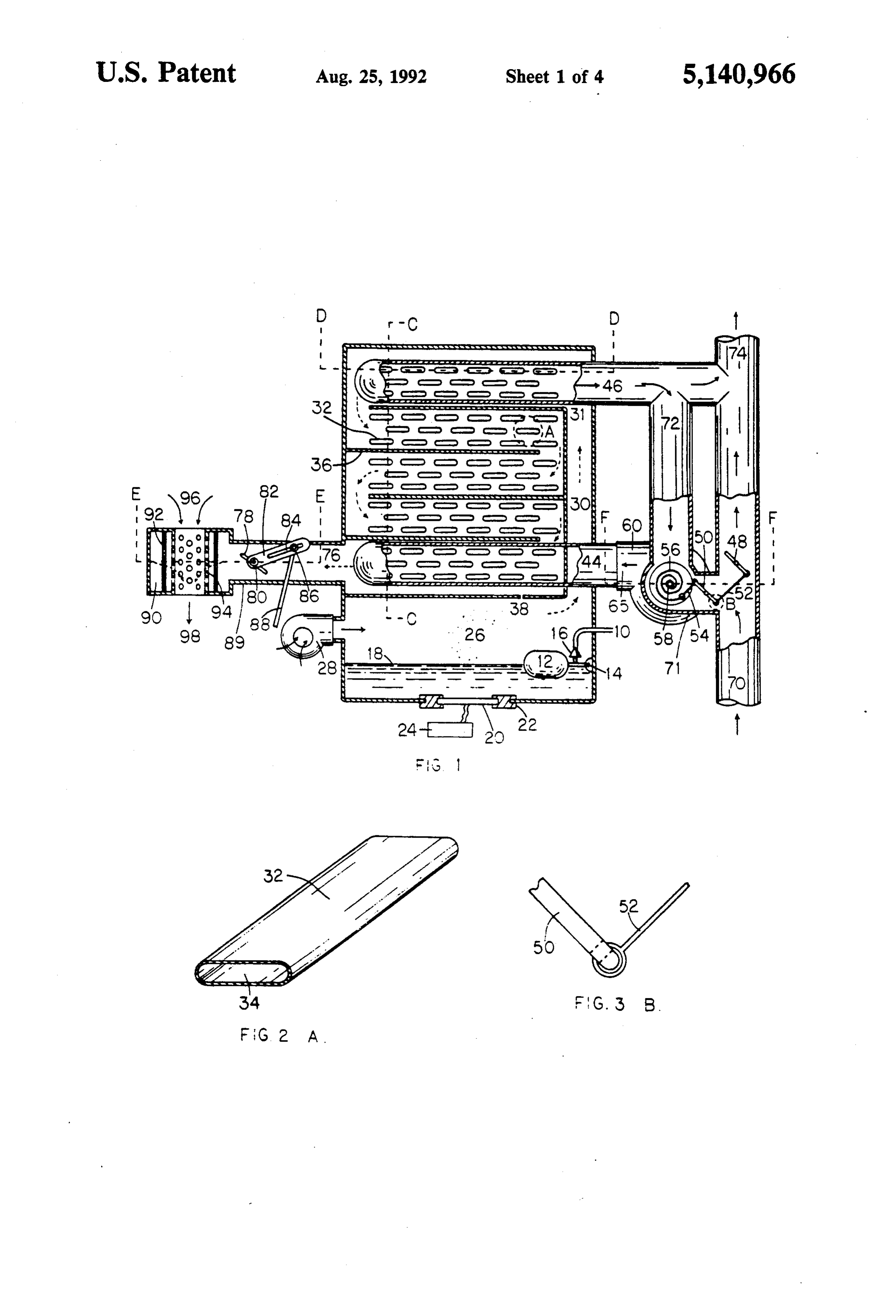
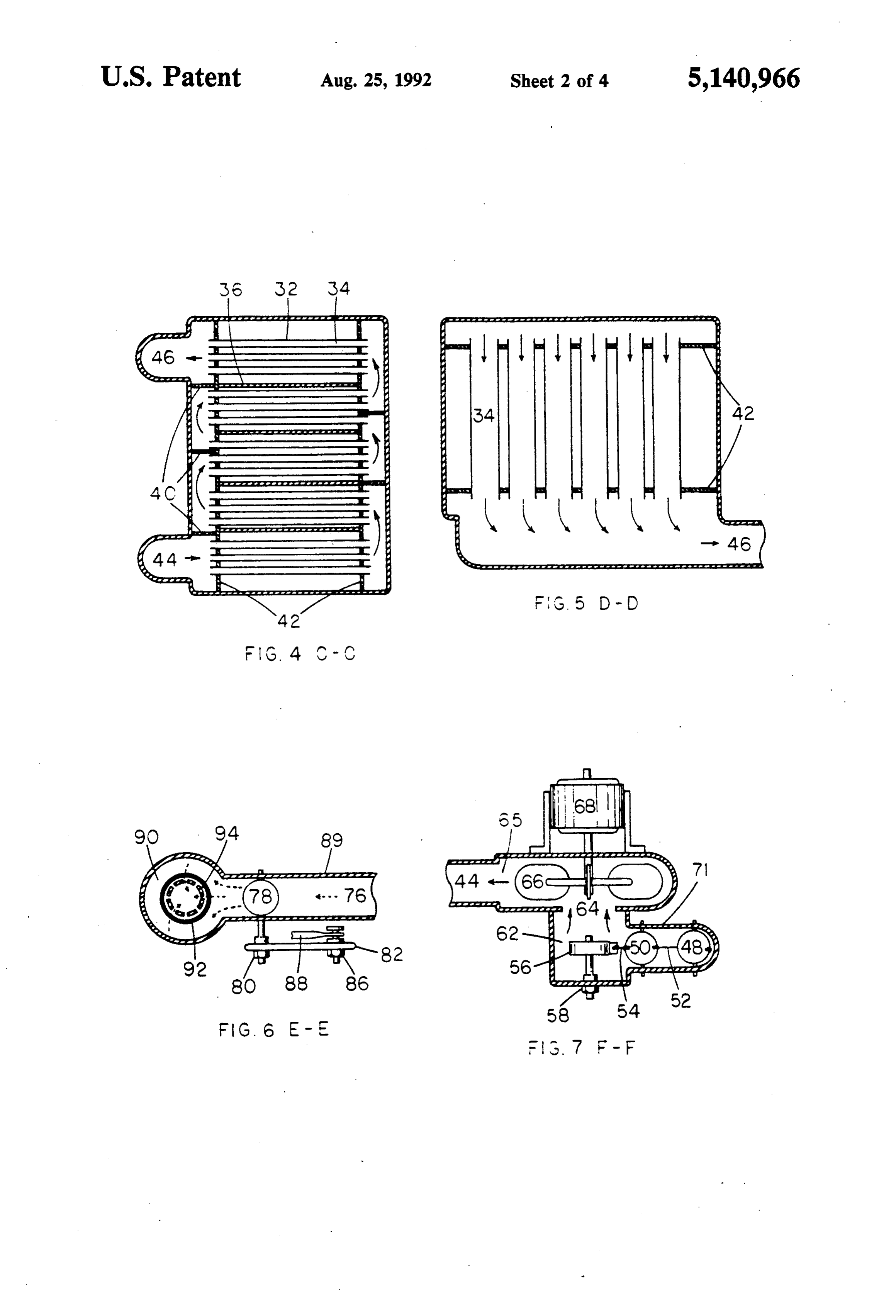
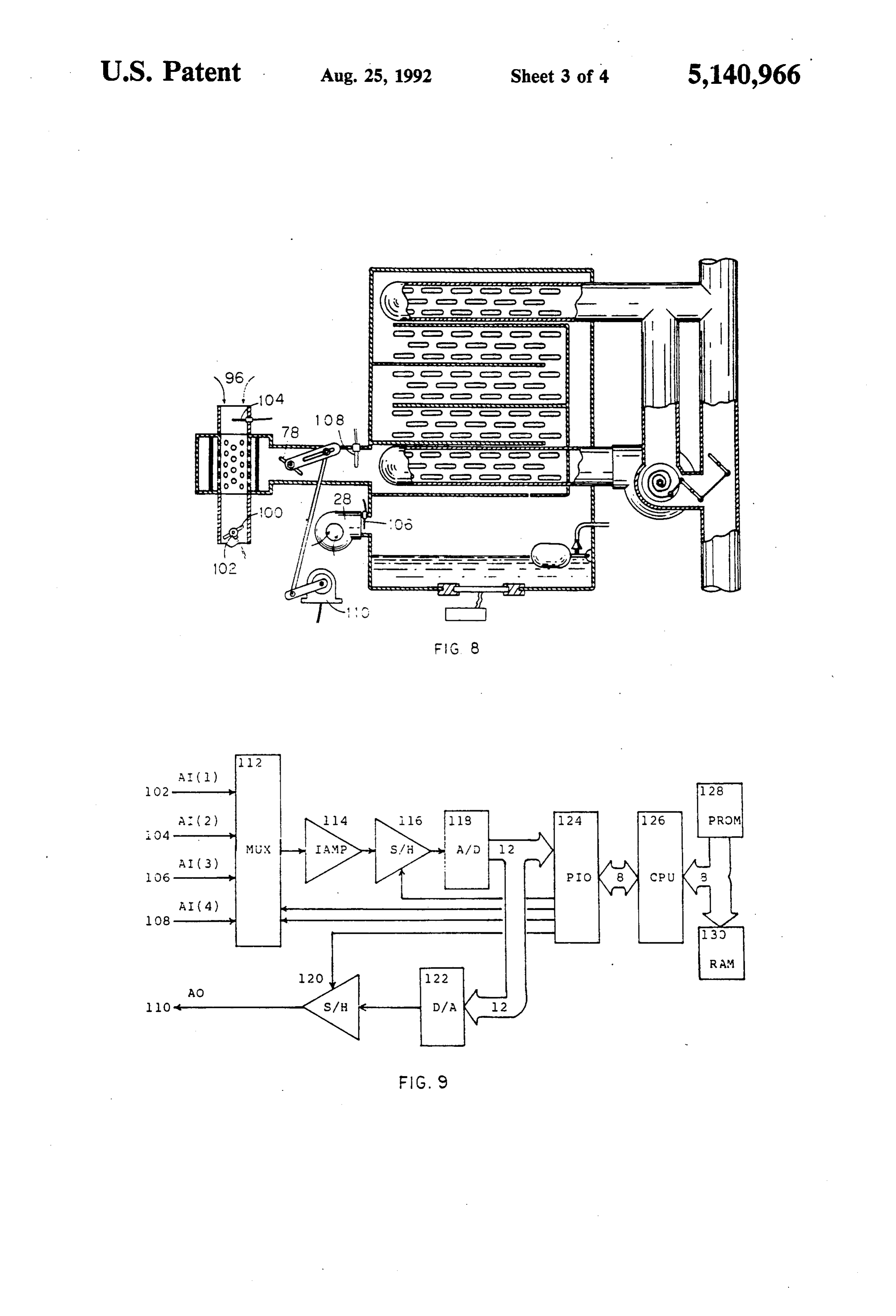
The drawings which illustrate embodiments of the heat exchanger via path 30. Optionally, an air filter can invention are as follows: be added in the air inlet of this air blower 28 to filter the FIG. 1 is the vertical cross-sectional view of the air. It should be noted, only a small amount of air is used carburetor. as a carrier for the fuel mist and it is only this small FIG, 2 is the detail view of the heat exchanger ele 35 amount of air that is heated. The majority of the intake ment labelled A in FIG. 1 which is made of very thin air 96 for combustion is still unheated before entering metal flat hollow tube for exhaust gas passage. the engine. It is observed that by minimizing the amount FIG. 3 is the detail view of the valve linkage labelledof heated intake air, detonation caused by high intake B in FIG. 1. air temperature is minimized and the maximum power FIG. 4 is the vertical sectional view of the heat ex output of the engine is also preserved. The ultrasonic changer on the line C-C in FIG. 1 detailing the ex technology is employed for fuel atomization because of haust gas passage and the direction of flow. its ability to produce ultra fine fuel droplets. When these FIG. 5 is the horizontal sectional view of the heat ultra fine droplets contact the heated surface of the heat exchanger on the line D-D in FIG. 1 indicating the exchanger, the fuel is vaporized so readily that gum direction of exhaust gas flow. 45 ming is not possible. The ultrasonic transducer in this FIG. 6 is the horizontal sectional view of the vapour design always produces adequate atomized fuel for fuel metering valve and the backfire arrester on the line maximum engine operation. The fuel mixture inside the E--E in FIG. 1 indicating the direction of vaporized heat exchanger is always maintained in saturated equi fuel flow. librium by the excess production of this atomized fuel. FIG. 7 is the horizontal sectional view of the temper 50 In the heat exchanger, the air laden with liquid drop ature control apparatus on the line F-F in FIG. 1 lets of fuel enters the inlet 31 at the top of the heat indicating the direction of exhaust gas flow. exchanger. As it travels in zigzag fashion down the heat FIG. 8 is the vertical cross-sectional view of the exchanger, fuel vaporizes rapidly in contact with the carburetor detailing the instrumentation of the mi heated surface 32 which consists of flat thin metal hol crocomputer control system. 55 low tubes. The flow of this fuel laden air is created by FIG. 9 is the hardware block diagram of the mi the blower 28. After vaporization, the vaporized fuel is crocomputer control system. extracted from the outlet 76 at the bottom of the heat FIG. 10 is the software flow diagram of the air to fuel exchanger for engine consumption. It is observed that ratio control algorithm. the finer the atomized fuel droplets, the more rapidly
DETAILED DESCRIPTION OF THE
the vaporization occurs in the heat exchanger and less
INVENTION
gumming occurs. Baffles 36 are configured to provide a zig zag passage for the atomized fuel to travel so that
Referring to the drawings, in particular FIG. 1, liquid the volume of the heat exchanger is used effectively. fuel is atomized in the fuel atomization chamber (item The passages of the exhaust gas and atomized fuel are in 10 to 28), and then injected into the heat exchanger ( a counter flow manner for the most effective heat trans item 30 to 46 and 76) for vaporization. The temperature fer and minimal occurence of gumming. The hot ex of the heat exchanger is controlled by the temperature haust enters the inlet 44 at the bottom of the heat ex control apparatus (item 48 to 74) such that atomized changer. The end plates 42 ( FIG. 4, 5), where the
Page 9
hollow tubes 32 are mounted, separate the exhaust gas tion blower 60. This enables a more uniformly high and the atomized fuel. Baffles 40 ( FIG. 4) enable the temperature throughout the heat exchanger, thereby exhaust gas to travel upward in a zig zag fashion vaporization of the fuel is achieved more readily. This through the inside of the flat hollow tubes 34 (FIG. 2, circulation blower also creates a turbulent flow of the 4, 5 and exit from outlet 46 at the top of the heat ex exhaust gas, as opposed to laminar flow, inside the heat changer. As the atomized fuel travels down the heat exchanger, thus further enhancing the heat transfer exchanger, temperature becomes higher because of the efficiency. Normally, the engine exhaust is too hot to be counter flow arrangement. It is known that high ends of injected into the heat exchanger in large amount with the hydrocarbon require more time and higher tempera out risking igniting the fuel. But since this circulation ture to vaporize. This counter flow arrangement and O blower draws cooled recirculation exhaust gas 72 and the from-top-to-bottom vapour path design ensure that combines it with the engine exhaust gas 70, large the high ends of the hydrocarbon have adequate time amount of engine exhaust can be utilized. The heat of and a high enough temperature to vaporize. If there is this engine exhaust, which otherwise would have been any fuel still in liquid form, passage 38 is designed to wasted can be extracted for vaporization. allow this liquid fuel to flow back to the fuel atomiza 15 The unique temperature control apparatus, which tion chamber for the new generation. This heat ex consists of the circulation blower 60, bimetal actuator changer also serves as a reservoir for this vaporized fuel 56 and the dual unison valves 48 and 50, facilitates a which is maintained at saturated equilibrium, indepen unique control mechanism. The bimetal actuator situ dent of the engine demand, and in optimum combustion ated in the gas streams of engine exhaust gas 70 and the state ready for engine consumption. 20 recirculation gas 72 constitutes a combination of feed The temperature of the heat exchanger is controlled forward and feedback control system. During the by a specially designed apparatus which consists of a startup, valve 48 is closed and valve 50 is open, there temperature sensitive bimetal actuator 56, valves 48 and fore the bimetal actuator responds mainly to the ten 50, and a circulation air blower 60. This bimetal actua perature of the engine exhaust gas 70. This control tor 56, situated in inlet 64 (FIG. 7) of the circulation 25 scheme which controls the effect of the engine exhaust blower 60, contracts or expands in response to the tem gas 70 by adjusting the dual unison valves 48 and 50 perature. This in turn controls the two butterfly valves before it materializes is called feedforward control. In 48 and 50. Valve 48 is situated in the exhaust line 70 of this situation, it is particularly important because if the the internal combustion engine. Valve 50 is situated in temperature of the heat exchanger is raised by the en the secondary exhaust line 71 leading from the exhaust 30 gine exhaust gas 70 to some point, the fuel in the heat line 70. The butterfly valves 48 and 50 are controlled in exchanger might be ignited. Obviously, it is desirable to unison via linkages 54 and 52 so that when one valve is employ feedforward control during startup phase of the closed the other is open in exact proportion. This in operation. As the temperature rises, the bimetal actua verse coupling movement of these valves enables a tor 56 closes valve 50 to limit the engine exhaust gas 70 constant cross-sectional area for the flow of the exhaust. 35 going into the heat exchanger, the temperature which The circulation air blower 60, with the fan 66 (FIG. 7 the actuator 56 is sensing is primarily the recirculation ) driven by the motor 68 (FIG. 7) draws the engine exhaust gas 72. A control scheme which controls the exhaust gas 70 via the secondary exhaust line 71 and the effect after it has materialized, in this case the actuator cooled recirculation exhaust gas via the recirculation senses the recirculation exhaust gas temperature 72 and line 72 into the mixing chamber 62 (FIG. 7) where the controls the dual unison valves 48 and 50 to achieve the temperature sensitive bimetal actuator 56 resided. It desired temperature, is called feedback control. During should be noted that the motor 68 (FIG. 7) is thermally steady state, it is desirable to consider the amount of isolated from the fan 66 (FIG. 7) and the rest of the heat used in the heat exchanger and then control the blower housing so that the motor cannot be damaged by amount of heat going into the heat exchanger. There excessive temperature. This bimetal actuator controls 45 fore feedback control is preferred during the steady the position of valves 48 and 50 in response to the tem state operation. Because of the safety reason, this tem perature in this chamber 62. This unique unison valves . perature control apparatus is designed to provide com 48 and 50 and the circulation blower 60 arrangement bination of feedforward and feedback control during enables the amount of engine exhaust gas 70 to be di engine operation. The temperature setpoint of this verted into the heat exchanger proportionally accord 50 counter flow heat exchanger can be adjusted by rotat ing to the demand without increasing the engine ex ing the bimetal actuator 56 and fixing it in position by haust back pressure. The proportion of the engine ex tighting the nut 58.
haust gas 70 and the recirculation exhaust gas 72 is The atomized liquid fuel after passing through the determined by the position of the valves 48 and 50. heat exchanger becomes truly vaporous. This vaporous Hence the heat exchanger inlet temperature can be 55 fuel comes out of the bottom of the heat exchanger via regulated at a predetermined optimum temperature. outlet 76 into the fuel vapour passage 89. Depending on The hot exhaust is forced by the air blower 60 the demand of the engine operation, the amount of fuel through the outlet 65 of the blower into the inlet 44 at is metered by the vapour fuel metering valve 78, which the bottom of the heat exchanger. Inside the heat ex is a butterfly valve connected through an extension arm changer, heat of the exhaust is transferred to the fuel 82 and a rod 88 to the electro-mechanical actuator 110 causing it to vaporize. After passing through the heat ( FIG. 8). This actuator is controlled by a specially exchanger, the exhaust gas exits from the outlet 46 at designed microcomputer control system. Detailed de the top of the heat exchanger and becomes cooler, a scription of this control system is presented later in this portion of this exhaust circulates back to the heat ex section. As the engine throttle valve opens, the vapour changer via the recirculation line 72 and the rest com 65 fuel metering valve also opens in unison according to bines with the main exhaust 70 and is exhausted to the the predefined control strategy. The idling position of environment 74 or via a muffler system. The exhaust gas this vapour fuel metering valve can be adjusted by ro is circulated within the heat exchanger by this circula tating the valve 78 to the desired position and fixing in
Page 10
place by tighting the nut 80. The slot 84 in the extension denotes Multiplexer presents one of these analog signals arm 82 is designed to provide the span adjustment on to its output according to the selection signal from the the fuel metering valve. The rod 88 can be slided along microprocessor. Optionally, component 114 IAMP the slot 84 for this span adjustment and can be fixed in which stands for Instrumentation Amplifier can be used position by tighting the nut 86. This metered vaporous to condition and amplify the signal if it is too weak. This fuel is then passed through a specially designed backfire signal after amplified is presented to the component 116 arrester in which it is combined with the main intake air S/H which denotes Sample and Hold. The function of 96 before being injected into the intake manifold 98 of this Sample and Hold is to provide a constant analog the engine. The main intake air.96 is filtered air, the air signal to the component 118 A/D during the analog to filter is not shown in the drawing. This backfire arrester O digital convertion. A/D is the Analog-to-Digital con consists of a cylinder having porous sidewalls 94 of fine vertor which as the name implies converts the analog mesh metal screen 92. During the engine operation, the signal to digital form so that the microprocessor can vaporized fuel travels through the passage 90 substan manipulate. In this design a 12 bit analog-to-digital con tially surrounding the cylinder such that vaporized fuel vertor is used as shown in the data bus of the diagram. from this passage passes through the porous sidewalls 15 This digital signal is presented to the component 124 94 of the cylinder thereby mixing with the intake air 96 PIO which denotes Parallel Input and Output device. to from the explosive mixture for engine consumption. The PIO is used by the microprocessor for interfacing Normally, the fine mesh metal screen imposes resistance to air passage, therefore a large fine mesh screen is with the the external device. The component 126 CPU is heart of this microcomputer. CPU which stands for employed to compensate this effect. When backfiring Central Processing
Unit is the microprocessor. In this occurs, heat is dissipated in the fine mesh metal screen design an 8bit microprocessor is employed as indicated thereby protecting the vaporized fuel from ignition.
In order to control the precise air to fuel ratio of the memory consists of componentsand in the data bus between the PIO its memory. The 128 PROM which mixture, a specially designed microcomputer control denotes Programmable Read Only Memory and 130 system is employed. This microcomputer control sys 25 RAM which denotes Ramdom Access Memory. The ten gathers information from the various sensors, per memory PROM is where the software program resided. forms the calculations and activates the control accord
The memory RAM is used for storing variables and ingly. FIG. 8 details the various sensors and the actua intermediate tor arrangement. The engine demand is sensed by the data. The control signal as calculated by throttle valve position sensor 102 which measures the 30 the microprocessor is presented via component 122 D/A which denotes Digital-to-Analog convertor. This opening angle of the throttle valve 100 and outputs a converted analog signal is latched by the component corresponding electrical signal to the microcomputer.
According to this demand signal the microcomputer 120 S/Hwhich is another Sample and Hold. The output controls the vapour fuel valve 78 via the electro Output of this sample and hold circuit denoted AO as Analog mechanical actuator 110 accordingly. This initial con 35 in the diagram is presented to the electro trol output is not very precise, it is designed to provide mechanical actuator 110. The hardware block diagram a fast response to the engine demand. However, this presented in FIG. 9 can be simplified with employment initial response is determined by the data obtained from of more sophisticated integrated circuits. There are the previous laboratory experiments on the engine integrated circuits that perform combined functions under control, therefore the resulting fuel mixture such as the microcontroller unit 68705 from Motorola should not deviate much from the optimum. After the which combines the CPU, PROM, RAM and PIO func initial response, the microcomputer reads in the main tions into one integrated circuit. In effect, components intake air flow 96 via the flow sensor 104 and the heat 124, 126, 128 and 130 can be replaced by one single exchanger air flow via sensor 106. Since the heat ex integated circuit. Further more, some integrated cir changer is a closed system, the air flowing through the 45 cuits also incorporate the A/D convertors as well such air blower 28 is the same as the air flowing through the as the microcontrollers 6805 and 6811 from Motorola. vapour fuel valve 78. The microcomputer also reads in FIG. 10 is the software flow diagram for controlling the vapour fuel temperature via sensor 108. Since the the proper air to fuel ratio, comprising the steps of: vaporous fuel inside the heat exchanger is maintained in Step 1 reads in the engine throttle valve position saturated equilibrium, with known vapour fuel tempera 50 which is the engine demand.
ture and the heat exchanger airflow, fuel flow is readily Step 2 determines whether the position is different calculated. With known air flow which is the summa from the last position significantly. If it is not, the pro tion of the main intake air flow and the heat exchanger gram skips the vapour fuel valve adjustment and per air flow, air to fuel ratio is obtained. From the experi forms the fuel mixture refinement process. ments, it is observed that the lean limit is the function of 55 Step 3 adjusts the vapour fuel valve according to the the degree of fuel vaporization which can be estimated change of throttle position proportionally. This step is by the vapour fuel temperature, therefore the lean limit to provide a fast engine response according to the en can be calculated. By comparing the actual air to fuel gine demand.
ratio with the lean limit, the microcomputer refines the Step 4 reads in the rest of the sensor signals, namely control by adjusting the vapour fuel valve 78 via the the main intake air flow, heat exchanger air flow and electro-mechanical actuator 110 so as to achieve the vapour fuel temperature.
optimum air to fuel ratio. Step 5 performs the calculations. They are as follows: FIG. 9 is the hardware block diagram of this mi a: Total air flow is the summation of the main intake crocomputer control system. All the components air flow and the heat exchanger air flow. shown in the diagram are integrated circuits. The sensor 65 b: The fuel vapour in the heat exchanger is always signals 102,104,106 and 108 are presented to the MUX maintained in Saturated equilibrium, with known as AE(1), AIC2), AI(3) and AIC4) respectively. AI stands fuel vapour temperature and the heat exchanger air for Analog Input. The component 112 MUX which flow, the amount of fuel flow can be calculated.
Page 11
c: Air to fuel ratio is calculated by dividing the total proportionally and as the first valve closes the air flow by the fuel flow, second valve opens proportionally. d; The lean limit is obtained by table look up tech 2. An improvement in a vaporization carburetor heat nique. The lean limit is the function of the degree of exchanger communicating with a secondary exhaust fuel vaporization. The higher the degree of vapori 5 line leading from an exhaust line of an internal combus zation the leaner is the lean limit. The lean limit tion engine, the improvement comprising: table is obtained by a series of experiments on the a) a first valve in the exhaust line; engine with different vaporization temperature. b) a second valve in the secondary exhaust line; and Step 6 tests whether the mixture is too rich compared c) means for inversely coupling the movement of the with the lean limit. If the mixture is too rich, the pro 10 first valve and the second valve to maintain a con gran proceeds to step 8. stant cross-sectional area for the flow of exhaust Step 7 tests whether the mixture is too lean compared gas, such that as the first valve opens the second with the lean limit. If the mixture is too lean, the pro valve closes proportionally and as the first valve gram proceeds to step 9. closes the second valve opens proportionally. Step 8 closes the vapour fuel valve proportionally 15 3. A method of improving the heat transfer efficiency according to how rich the mixture is, and proceeds to of a vaporization carburetor heat exchanger, compris repeat the algorithm. ing the steps of
Step 9 opens the vapour fuel valve proportionally a) feeding a flow of air laden with liquid droplets of according to how lean the mixture is, and proceeds to fuel into a first inlet at a top of a heat exchanger repeat the algorithm. such that the fuel laden air follows a first zigzag During the transient situations such as acceleration, path from the top to a first outlet positioned at a deceleration and load variations, the software program bottom of the heat exchanger; and always excecutes step 3 to provide fast response to the b) using a blower to create a turbulent counter flow engine demand. During the steady state, the program of hot exhaust gas which enters a second inlet at the skips step 3 and adjusts the vapour fuel valve in step 8 or 25 bottom of the heat exchanger and follows a second 9 as necessary. Since the present microprocessor is ca zig zag path from the bottom to a second outlet pable of executing millions of instructions per second positioned at the top of the heat exchanger, thereby and the software program in this design consists of only providing the liquid droplets of fuel uniformly high a few hundred instructions, appropriate time delays or temperatures within which to vaporize. employment of real time scheduling have to be imple 30 4. A method of controlling the heat exchanger tem mented in the control system and the software program perature in a vaporization carburetor heat exchanger to slow down or schedule the execution so that it does having a blower, comprising the steps of: not perform the algorithm more than 2 or 3 times a a) placing a cooled exhaust gas recirculation line second. The reason is the interfacing mechanical de leading from an outlet of a heat exchanger to the vices are slow in response. To further enhance the oper 35 inlet of the blower;
ation, more sensors can be added to the control system b) placing a valve in a secondary exhaust line leading such as engine speed, engine and ambient temperatures, from an exhaust line of an internal combustion knock sensor and exhaust emission sensors etc. With engine to the inlet of the blower; this added information, more precise fuel mixture and c) placing the blower outlet to the inlet of the heat improved performance can be expected. More precise exchanger; and heat exchanger temperature can be controlled by this d) placing temperature sensitive valve control means microcomputer control system as well. Referring to at the junction of the recirculation line from the FIG. 1, temperature sensors can be added to the heat heat exchanger outlet and secondary exhaust line exchanger inlet 44 for measuring the temperature of the from the exhaust line such that the valve control combined engine exhaust gas and the recirculation ex 45 means adjusts the proportions of exhaust gases haust gas, and to the recirculation exhaust gas 72 and from the recirculation line and the exhaust line to the engine exhaust gas 70. With these signals, a sophisti maintain the temperature of the gases entering the cated temperature control algorithm can be imple inlet of the heat exchanger constant at a predeter mented by the microcomputer control system. The heat mined optimum temperature. exchanger temperature can be controlled by this con 50 5. An improvement in a vaporization carburetor heat trol system via a electro-mechanical actuator on the exchanger having a top, a bottom, a fuel vapour passage unison valves 48 and 50. arranged in Zig Zag fashion and communicating with a The embodiments of this invention in which an exclu fuel atomization chamber, a gas flow passage arranged sive property or privilege is claimed are defined as in zigzag fashion and communicating with a secondary follows: 55 exhaust line leading from an exhaust line of an internal 1. A method of metering the flow of exhaust gas combustion engine, the improvement comprising: through a heat exchanger connected by a secondary a) the fuel vapour passage having a first inlet at the exhaust line to an exhaust line of an internal combustion top, and a first outlet at the bottom of the heat engine without increasing engine exhaust back pressure, exchanger;
comprising the steps of b) a first blower communicating with the fuel vapour a) placing a first valve in the exhaust line; passage thereby creating a flow of fuel laden air b) placing a second valve in the secondary exhaust through the fuel vapour passage; line leading from the exhaust line to the heat ex c) the gas flow passage having a second inlet at the changer; and bottom, and a second outlet at the top of the heat c) inversely coupling the movement of the first valve 65 exchanger;
and the second valve to maintain a constant cross d) a second blower communicating with the inlet of sectional area for the flow of exhaust gas, such that the gas flow passage thereby creating a counter as the first valve opens the second valve closes flow of exhaust gas, through the gas flow passage,
Page 12
with respect to the fuel vapour flow of the fuel junction of the recirculation line and the secondary vapour passage; exhaust line such that the valve control means e) a cooled exhaust gas recirculation line leading from adjusts the proportions of the exhaust gases from the second outlet to the inlet of the second blower; the recirculation line and the secondary exhaust f) a valve in a secondary exhaust line leading from the 5 line to maintain the temperature of gases entering exhaust line of the engine to the inlet of the second the second inlet of the heat exchanger constant at a blower; and predetermined optimum temperature. g) temperature sensitive valve control means at the
Provenance
- Collection
- Cited prior art
- Original PDF
- patentimages.storage.googleapis.com →
- Filed
- 1991-06-04
- Pages
- 12
- Method
- pdftotext (the PDF's own text layer) + pdftoppm 300dpi page scans
- Source
- Google Patents bibliographic record
- Granted
- 1992-08-25
- Inventors
- Men L. Wong
- Transcribed from
- patentimages.storage.googleapis.com →