patent · US4594990
Carburetor for gaseous fuel
17 June 1986
Page 1 — bibliographic record
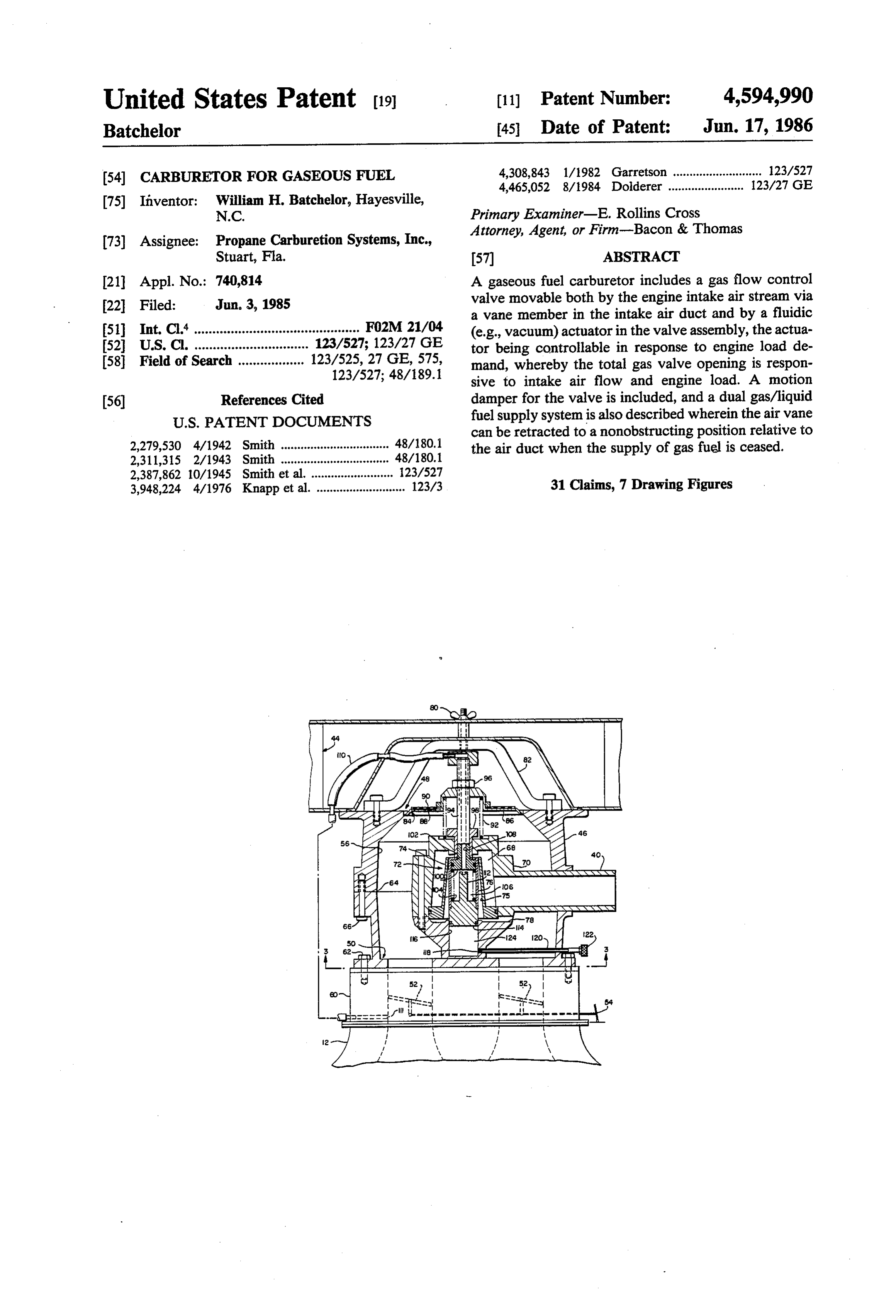
United States Patent (19) (11 Patent Number: 4,594,990 Batchelor 45 Date of Patent: Jun. 17, 1986 (54) CARBURETOR FOR GASEOUS FUEL 4,308,843 1/1982 Garretson ........................... 123/527
75) Inventor: William H. Batchelor, Hayesville,
N.C. Primary Examiner-E. Rollins Cross 73) Assignee: Propane Carburetion Systems, Inc., Attorney, Agent, or Firm-Bacon & Thomas Stuart, Fla. 57 ABSTRACT 21 Appl. No.: 740,814 A gaseous fuel carburetor includes a gas flow control 22 Filed: Jun, 3, 1985 valve movable both by the engine intake air stream via a vane member in the intake air duct and by a fluidic 51) Int. Cl. ............................................. F02M 21/04 (e.g., vacuum) actuator in the valve assembly, the actua 52 U.S. C. ............................... 123/527; 123/27 GE tor being controllable in response to engine load de 58 Field of Search .................. 123/525, 27 GE, 575, mand, whereby the total gas valve opening is respon 123/527; 48/189.1 sive to intake air flow and engine load. A motion (56) References Cited damper for the valve is included, and a dual gas/liquid
can be retracted to a nonobstructing position relative to 2,279,530 4/1942 Smith ................................. 48/180.1 the air duct when the supply of gas fuel is ceased. 2,311,315 2/1943 Smith .............. ... 48/180.1 2,387,862 10/1945 Smith et al. . 123/527 3,948,224 4/1976 Knapp et al. ... ... 123/3 31 Claims, 7 Drawing Figures
Page 2
Drawing sheet — no readable text.
Page 3
Drawing sheet — no readable text.
Page 4
Drawing sheet — no readable text.
Page 5
More specifically, a basic control valve for gas fuel
CARBURETOR FOR GASEOUS FUEL similar to that described in the inventor's related patents uses a vane member in the intake air conduit to directly
FIELD OF THE INVENTION control the primary position of a gas flow control valve This invention relates to gaseous fuel carburetors 5 stream to supply a proper proportion of gas fuel to an intake air useful for the preparation of a charge for an internal internaldrawn into the intake manifold of an operating combustion engine in accordance with the set combustion engine. ting of a throttle at the inlet to the intake manifold. The BACKGROUND OF THE INVENTION air flow responsive vane member essentially reacts di O rectly to the force of flowing intake air to set the posi 1. Description of the Prior Art
Gaseous fuel carburetors useful for applications in tion of the gas flow control valve while gas fuel at a regulated pressure is supplied to the upstream side of internal combustion engines for motor vehicles have been exemplified numerous times in the prior art litera the valve. The quantity of gas admitted into the flowing ture and in commercial embodiments. Descriptions of 15 openingairprovided intake is ultimately determined by the effective by the valve.
typical prior art examples can be found in U.S. Pat. Nos. In accordance with this invention, the movable valve 2,311,315 granted to Smith on Feb. 16, 1943; 2,387,862 element for controlling gas flow is furthermore control granted to Smith and Paxton on Oct. 30, 1945; 3,948,224 lable in response to engine load to further adjust the granted to Knapp and Nesbitt on Apr. 6, 1976; and area of opening of the gas valve to either enrich or lean 4,308,843 granted to Garretson on Jan. 5, 1982. In ac 20 out the charge mixture independently of input motion cordance with these and other prior art teachings, vari ous control systems have been proposed by which the of the airflow responsive vane member. The means for achieving this is an actuator associated with the gas mixing of gas fuel with engine intake air is regulated so valve that enables as to produce a desired charge for the engine having a valve position. Thecontrolled adjustment of the final gas actuator preferably is constituted of proper fuel-to-air ratio for efficient combustion under 25 a vacuum operated fluidic motor formed within the varying load demands of the engine. An objective of moving valve part itself. By utilizing a lost motion and any such gas fuel metering system (normally character spring connection between the airflow responsive vane ized as a carburetor) is to provide a charge for the en member and the moving valve element, the fuel valve gine that is proper for varying engine operating condi position can be vacuum controlled independently of the tions, particularly under circumstances where enrich 30 setting of the air flow responsive vane member. The ment of the fuel is rapidly needed to meet the demand source of the vacuum used to control the final position for higher engine torque or speed by the operator of a of the valve is preferably the engine intake manifold at vehicle in which the engine is installed. a region downstream of the throttle so that the vacuum While the prior art suggests various means for con signal to the gas control valve is responsive to engine trolling the fuel/air ratio of a gas fuel supply system 35 load demand in accordance with well-known princi used for internal combustion engines, including systems ples.
utilizing vacuum signals having as their source intake This invention also provides a unique fluidic motion manifold pressure of the engine, such systems tend to be damper for controlling the rate at which the control complex, costly and difficult to maintain in proper ad valve can be displaced during its operation to thereby justment in the environment of an internal combustion prevent high speed valve flutter or sudden closing mo engine. Moreover, such systems usually require careful tion of the air flow responsive vane member during calibration for each engine and they are not generally various engine operating conditions. In addition, the adapted to be simply retrofit on existing engines as a fluidic motion damper may also be used in certain appli substitute for an existing liquid fuel carburetor or as an cations to displace the gas valve and the air flow re auxiliary carburetor for use in conjunction with existing 45 sponsive vane member in a positive manner to a fully liquid fuel carburetors constituting original engine open position whereat the intake air conduit of the equipment. engine is substantially unimpeded. This latter feature is SUMMARY OF THE INVENTION useful when it is desired to utilize the gas carburetor of the present invention in series with a liquid fuel carbure
This invention is a gas fuel carburetor that is uniquely 50 tor provided in the path of the intake air stream. adapted to control the mixture of gaseous fuel with All of the above-mentioned features are provided in intake air supplied to an internal combustion engine the gas fuel carburetor constructed in accordance with through the use of a gas flow control valve that is pri this invention in a simple, relatively low cost, efficient marily and directly responsive to the rate of flow of system that is readily usable in a retrofit application as engine intake air and secondarily responsive to engine 55 well as an original equipment installation. load demand to provide a variable fuel-to-air ratio DESCRIPTION OF THE DRAWINGS charge mixture to the engine during its operation.
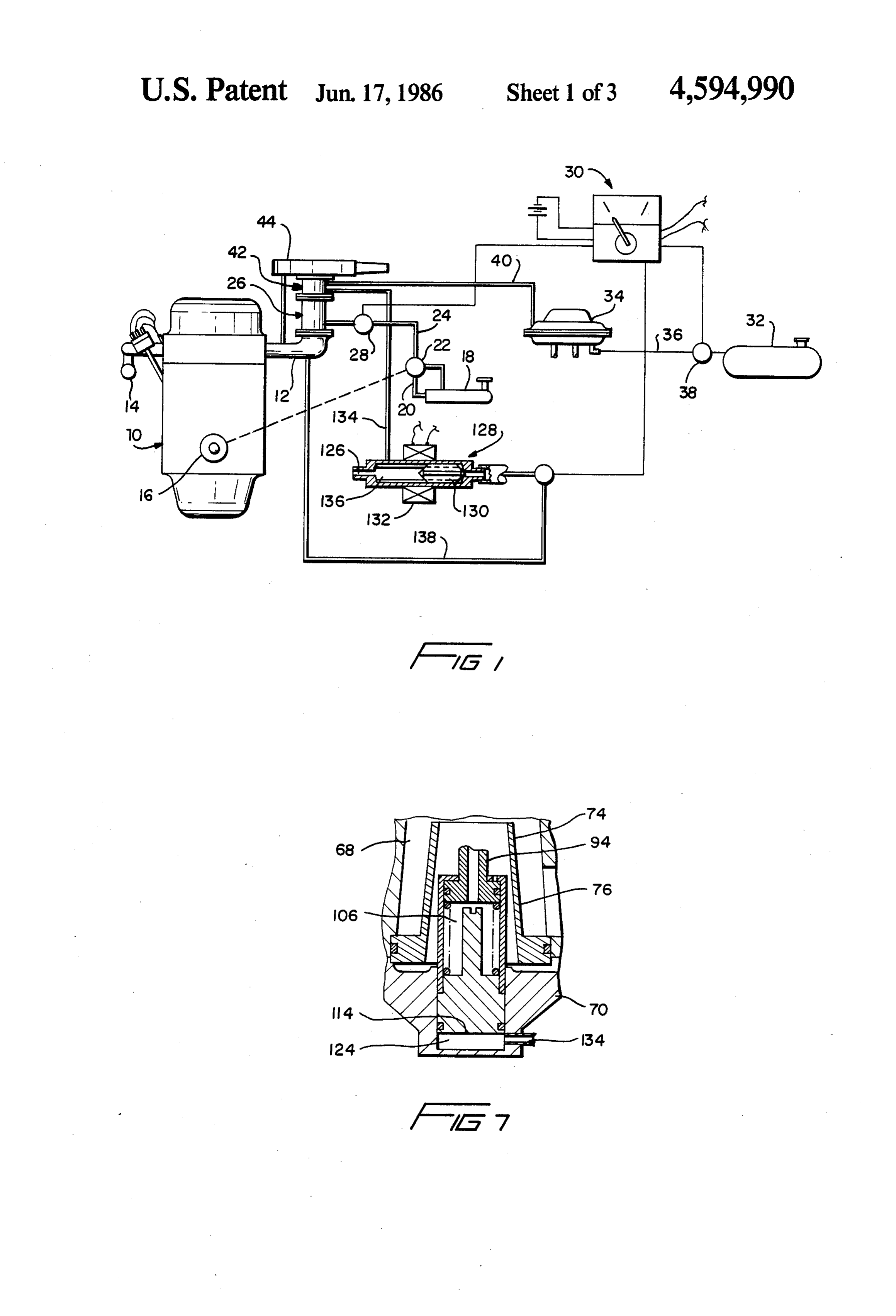
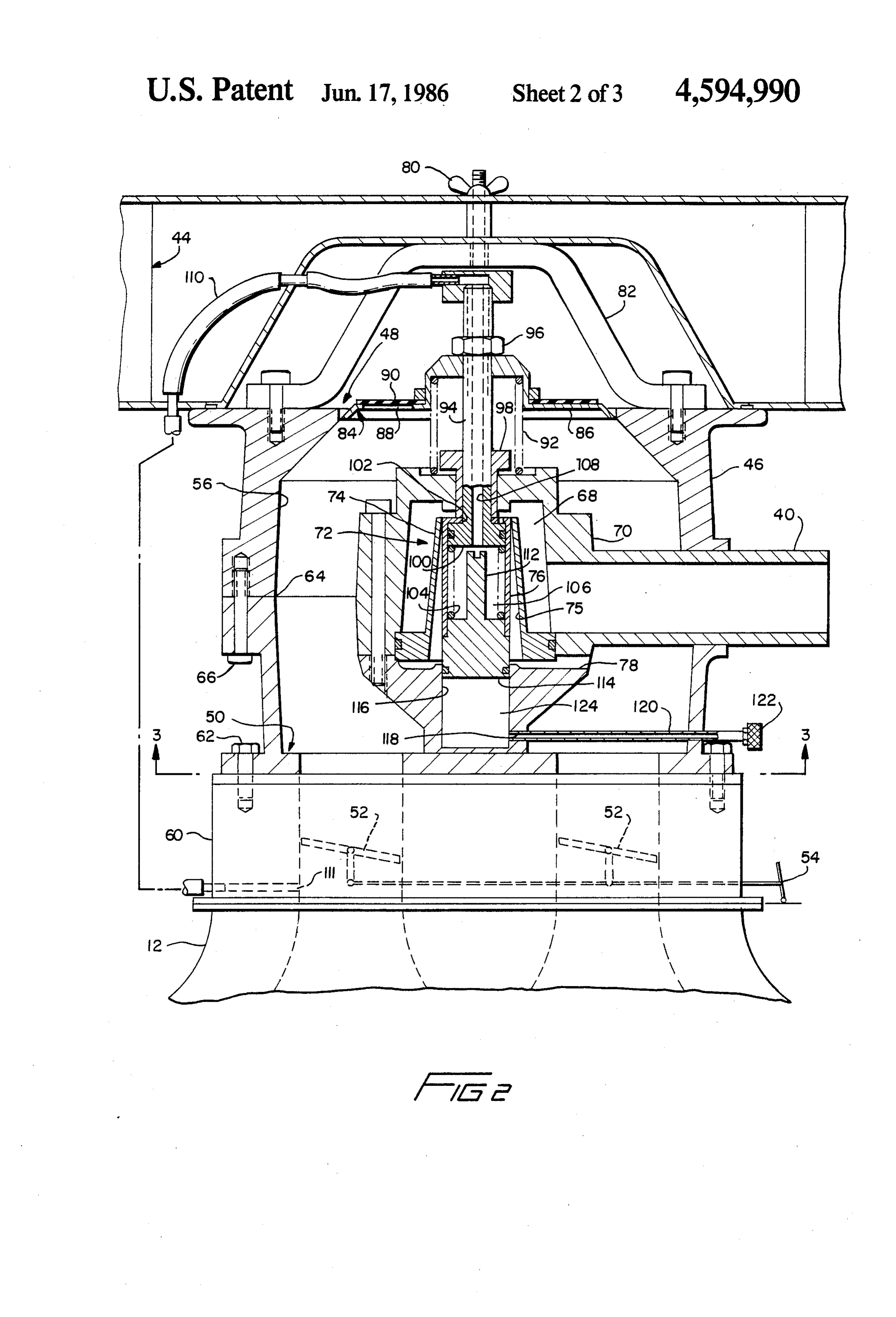
The basic valve configuration is broadly similar to FIG. 1 is a schematic view of an embodiment of a fuel that disclosed in co-owned U.S. Pat. Nos. 4,440,137 supply system in which this invention is incorporated; granted to the inventor named herein on Apr. 3, 1984 60 FIG. 2 is a sectional elevation view of a preferred and 4,513,272 granted to the same inventor on Apr. 30, embodiment of a gas fuel carburetor constructed in 1984. However, the control valves described in these accordance with this invention;
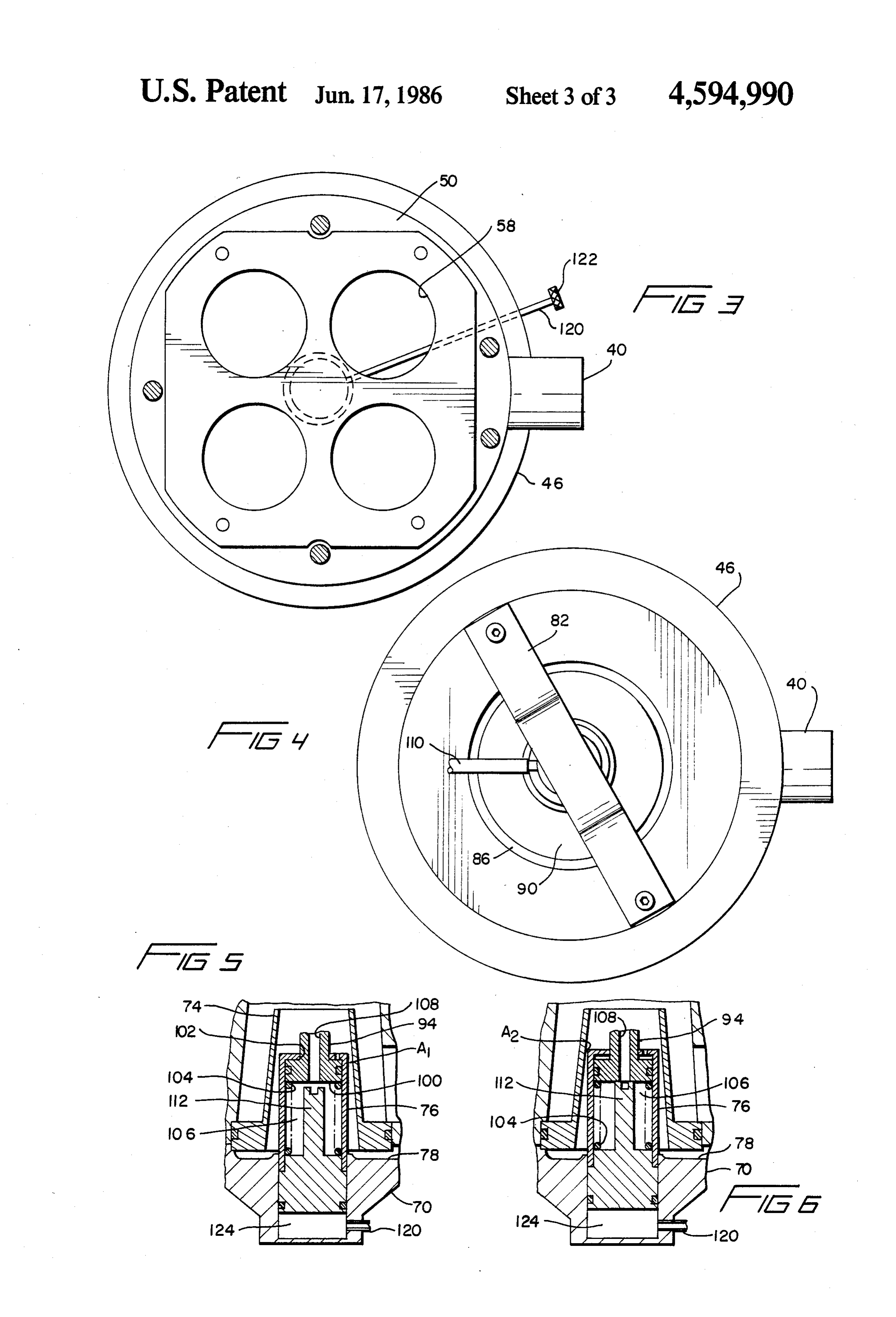
patents were intended primarily for engine applications FIG. 3 is a section view taken along line 3-3 of FIG. in which intake air essentially is unthrottled (e.g., fuel 2;
injected diesel engines). The present invention provides 65 FIG. 4 is a plan view of the carburetor shown in FIG. improvements in such control valves that render them 2 with the air filter removed; and particularly suitable for use in engines having intake air FIGS. 5, 6 and 7 are sectional elevation views of the throttles for controlling engine speed. gas valve of the carburetor at different settings.
Page 6
DETAILED DESCRIPTION OF PREFERRED includes a housing 46 having an air inlet end 48 and an EMBODIMENT air/gas fuel mixture outlet end 50. In the embodiment of FIG. 2, the gas fuel carburetor has been eliminated for
With reference to the drawings, FIG. 1 illustrates simplicity to show the relationship between the housing schematically a dual fuel supply system for an internal 46, air intake manifold 12 of engine 10 (see FIG. 1) and combustion engine 10 including an air intake manifold throttle plates 52. The throttle plates 52 are controllable 12, an exhaust manifold 14, and an output shaft 16. A by a movable throttle 54 operable to regulate speed and liquid fuel supply source 18 includes a liquid fuel supply torque of engine 10. While two pairs of throttle plates conduit 20 in communication with a fuel pump 22 52 are usuable, in the embodiment of FIG. 2, these are driven by engine output shaft 16 or any other suitable O to be considered as exemplary only, since a single throt means. The output of liquid fuel pump 22 is supplied to tle plate could also be used to regulate flow of air and engine 10 via fuel line 24 and liquid fuel carburetor 26. fuel into intake manifold 12, provided that the intake A fuel shutoff valve 28 under the control of master fuel manifold inlet was properly configured. switch 30 selectively permits or blocks flow of fuel from An intake air conduit 56 extends through housing 46 liquid fuel pump 22 to liquid fuel carburetor 26. 15 between its inlet and outlet ends 48, 50, respectively. As It will be appreciated that the liquid fuel could be of shown in FIGS. 3 and 4, the outlet end of housing 46 any type usable by an internal combustion engine. In can be shaped with a suitable number of ports 58 com accordance with the embodiment illustrated in FIG. 1, municating with the throttle body 60 associated with the liquid fuel supply system and its associated carbure the entrance to intake manifold 12. Housing 46 is con tor are intended to be exemplary only to show that it is nected to the throttle body 60 in the embodiment illus possible in a typical setting to use the gas fuel carburetor trated in FIG. 2 by means of suitable fasteners 62. Any according to the present invention in combinatin with a form of spacer, insulator or other apparatus commonly liquid fuel supply system for the engine, including a used in connection with carburetor assemblies can be typical liquid fuel carburetor. The liquid fuel supply utilized to attach housing 46 to intake manifold 12. system does not constitute a part of this invention perse 25 Housing 46, in accordance with the preferred em and therefore no further explication is made respecting bodiment, is constructed in two halves divided along the liquid fuel supply system save for additional com joint 64 and retained together by fasteners 66. Within ments that will be made respecting the liquid fuel supply the housing 46, there is provided a gas plenum chamber shutoff valve 28 and the master switch 30, which will be 68 that is in communication with gas fuel line 40, as discussed in somewhat more detail below. 30 shown. Manifold chamber 68 preferably is formed The gas fuel supply system for engine 10 comprises a within a hollow manifold housing 70 that includes a gas gas fuel supply vessel 32 adapted to contain a suitable fuel valve assembly 72 within the manifold 70. The gas fuel that can be supplied to engine 10 in gaseous form. valve assembly 72 includes a fixed valve port 74 in the Such a fuel, for example, could be propane, liquified form of a tapered opening 75 and a movable valve plug natural gas, compressed natural gas or any other suit 35 76, the port 74 comprising a fixed opening through able fuel usable in gaseous form by engine 10 through which gas fuel can flow from manifold chamber 68 into the use of a gaseous fuel carburetor or other suitable conduit 56 within housing 46 when the valve plug 76 is mixing valve arranged to control the supply of the gase moved away from the opening of port 74. The fixed ous fuel and air mixture to the engine in proportion to port 74 preferably includes a tapered portion as shown engine power demand or speed setting. whereby, upon motion of plug member 76 away from In accordance with the preferred embodiment of this the opening of the port member 74 progressively opens invention, gaseous fuel in vessel 32 in highly com the port 74 to the passage of gas fuel supplied through pressed form (including liquified) is supplied to a gas fuel line 40 to gas fuel manifold 68. vaporizer/pressure control valve 34 via gas fuel line 36. The lower portion of manifold 70 includes transverse A gas fuel shutoff valve 38 controls the supply of gase 45 openings 78 for admitting gas fuel from manifold 68 ous fuel to the valve 34 under the control of master fuel passing through the valve assembly 72 into the conduit control switch 30. 56 for mixing with engine intake air flowing through The vaporizer/pressure control valve 34 convention conduit 56. The rate at which gas flows into air conduit ally includes a heat exchanger (not illustrated) to com 56 depends upon the relative position established be pletely vaporize fuel from vessel 32 supplied through 50 tween the fixed and movable parts of the valve assem line 36 and also includes one or a series of pressure bly 72. While a fixed port 74 and a movable plug 76 are control regulators to limit the output pressure of gase shown in the preferred embodiment, it is to be under ous fuel to the gas fuel supply line 40 which ultimately stood that this invention could be applied as well to a provides gas fuel to engine 10 via gas fuel carburetor 42. reverse situation in which a port could be movable It will be noted that, in accordance with the embodi 55 relative to a fixed plug constituting the valve assembly. ment shown in FIG. 1, gas fuel carburetor 42 is up Air cleaner 44 is secured to the housing 46 adjacent stream of liquid fuel carburetor 26 and is provided with the inlet end 48. Air cleaner 44 is mounted by a suitable an air filter element 44. Thus, all of the intake air to fastener 80 to a fitting 82 secured to the inlet end of engine iO flows through the air filter 44, gas fuel carbu housing 46. The relationship and connecting means retor 42 and liquid fuel carburetor 26 before entering 60 illustrated for the air cleaner are purely exemplary, it engine intake manifold 12. If only a gas fuel supply being understood that any appropriate form of air system is to be used by the engine, the liquid fuel carbu cleaner connection to housing 46 could be utilized. retor 26 and its associated liquid fuel supply means can At the inlet end 48 of housing 46 there is disposed an be dispensed with, in which case gas fuel carburetor 42 air flow responsive member 84 including a vane element would be connected directly to air intake manifold 12 of 65 86 extending substantially totally across the air inlet the engine. opening to housing 46 so as to substantially block flow As shown in greater detail in FIG. 2, a gas fuel carbu of inlet air into the conduit 56 when the vane 86 is in its retor constructed in accordance with this invention normal at-rest position as shown in FIG. 2. Vane 86
Page 7
includes apertures 88 for permitting egress of pressur 56 and gas fuel manifold 68 upon the passage of intake ized gases in intake manifold 12, such as might occur in air through conduit 56. The combined effect of the the event of a backfire from the combustion chambers lower air pressure adjacent openings 78 and the pres of engine 10. A suitable elastomeric or other resilient sure of the gas fuel in inlet line 40 serves to effectively material cover 90 is disposed over apertures 88 so that cause valve plug 76 and rod 94 to virtually follow the only egress of air from conduit 56 is permitted through vertical movement of vane 86 in response to intake air apertures 88, and not reverse flow towards the engine. force against vane 86. Accordingly, the effective open Vane 86 is normally maintained at its closed position ing of port element 74 of valve 72 opens and closes in as illustrated by a spring 92 that normally biases vane 86 response to downward and upward movement of vane towards its upper closed position. Vane 86 is mounted 10 86, respectively, in response to greater or less flow of on rigid rod 94 by means of a connection permitted intake air into intake manifold 12. Opening of throttle vane 86 to slide along rod 94 vertically downwardly but plates 52 thus supplies additional air and fuel to engine not upwardly beyond lock nut 96 that is threaded on the 10 as the increased air flow moves vane 86 to a position upper end of rod 94. Thus, the upper limit of travel of causing an increased effective opening of gas fuel valve vane 86 is the position of nut 96 on rod 94. Spring 92 15 72.
normally maintains vane 86 up against the lock nut 96 It will be recognized that it would be highly desirable which, as will be explained in more detail below, is to vary the fuel mixture richness provided to the intake preset to establish a maximum upper limit of travel of air during engine operation and in particular to vary the vane 86 relative to housing 46. fuel mixture in accordance with engine loading over the Connector rod 94 extends vertically down through a 20 operating speed range of the engine. In accordance with bushing 98 and is connected to valve plug element 76 this invention, this is accomplished by providing a fluid through a lost-motion connection that will be described actuator that can fluidically move the valve plug 76 relative to the connector rod 94. Such an actuator is below.
Valve plug element 76 is configured in the form of a provided by the relationship between the enlarged end hollow cannister which defines within its interior vol 25 100 of rod 94 and the interior volume 106 of valve plug ume a cylinder for receiving enlarged end 100 of rod 94 76, whereby volume 106 is variable by controlling the in sealing and sliding relationship. The reduced portion pressure within volume 106 via fluid conduit 108 ex of rod 94 extends into valve plug 76through an aperture tending through rod 94 and in communication with 102 in the top end of the plug 76 as illustrated in FIG. 2. fluid conduit 110, conduit 108 and intake manifold 12 at A spring 104 within plug 76 normally biases the plug 76 30 a region 111 below throttle plates 52. With such an and rod 94 away from each other so as to maintain the arrangement, interior volume 106 of plug 76 is in com cylindrical volume 106 within plug 76 at maximum munication with the intake manifold below the throttle volume, with the top of the plug bearing against en plates 52 whereby, upon the occurrence of sufficient larged end 100 of rod 94. That is to say, spring 104 vacuum in interior volume 106 to collapse spring 104, normally biases plug 76 so that the combination of rod 35 the position of plug 76 along rod 94 is varied in a direc 94 and plug 76 is at maximum length, considering the tion to cause closing of the effective opening of valve total length of rod 94 and plug 76 as shown in FIG. 2. port 74. An end-limit stop 112 within plug 76 (which With the system at rest as shown in FIG. 2, it will be can be made adjustable if desired) limits the maximum seen that spring 92 urges vane 86 upwardly against an extent of upward travel of plug 76 relative to rod 94. adjustable stop nut 96 which in turn raises rod 94 to its 40 It will thus be apparent that, upon engine start-up, upper limit of travel whereat the top end of plug 76 rests vane 86 moves downwardly under the influence of against the bottom of bushing 98. In this position, plug intake air flow to a stable position against the bias of 76 virtually closes the opening in port 74 through which spring 92 causing plug 76 to likewise move downwardly gas can flow into openings 78 and subsequently into air to set the effective open area of port 74 to cause flow of flow conduit 56. If desired, the position of bushing 98 45 gas fuel through line 40 into air conduit 56 via openings can be adjusted to adjust the upper limit of travel of 78. However, under low engine loading conditions, a plug 76 if it is desired to preset the plug so as to provide high vacuum in intake manifold 12 will be immediately a small effective opening in port 74 for admitting gas communicated to the interior volume 106 of valve plug fuel during starting or idle conditions. 76 to cause upward movement of plug 76 relative to rod During normal operation of the gas fuel carburetor, 50 94, tending to slightly close the opening of port 74 to upon cranking of the engine to start same, air flow lean out the gas fuel mixture supplied to the intake air drawn into housing 46 from intake manifold 12 im stream. Normally, plug 76 will move upwardly until the pinges against vane 86 and causes same to be moved top of stop 112 strikes against the bottom of enlarged axially downwardly to provide an inlet air passageway end 100 of rod 94 and the valve plug 76 and rod 94 will into housing 46. Until the engine starts, motion of vane 55 move in unison in response to varying air flow through 86 is small, but adequate to permit the passage of intake conduit 56 as sensed by vane 86 which reacts to the air corresponding to the rate of flow of such air as is force of the intake air stream admitted to housing 46. permitted by opening of throttle plates 52. Movement of Upon opening of the throttle plates 52 to increase the vane 86 downwardly away from adjustable stop nut 96 speed or torque of the engine, as engine load increases against the bias of spring 92 immediately permits valve 60 the total pressure in intake manifold 12 increases, that is plug 76 to also move down in port 74 to increase its to say, the vacuum decreases. The interior volume 106 effective opening by reason of the suction effect of air of plug 76 experiences the same change in pressure, flowing through conduit 56 past openings 78 at the which ultimately permits spring 104 to begin moving lower end of manifold 70. the plug 76 longitudinally along rod 94 in a direction Conduit 56 preferably is formed so that there is a 65 tending to open port 74 to increase the flow of gas fuel small restriction to air flow in the vicinity of manifold to the intake air stream moving through conduit 56. 70, particularly in the region of openings 78, thereby Thus, without vane 86 changing its position (i.e., con creating a pressure differential between airflow conduit stant engine speed), fuel enrichment occurs due to the
Page 8
drop in manifold vacuum (i.e., increased absolute pres tive to the vane 86 and connecting rod 94, and more sure) resulting from the opening of the throttle plates over restricts the rate of motion of rod 94 and vane 86 52. The fuel enrichment tends to increase the speed of whenever rod 94 is at an end of travel limit position in the engine until the throttle plates 52 are adjusted to plug 76.
hold engine speed at a desired operating level, under The damper chamber 124 prevents fluttering of the which condition the position of the valve plug 76 again plug 76 in port 74. Fluttering of valve plug 76 is in stabilizes relative to rod 94 and vane 86 with an appro tended to generally connote any undamped oscillation priate supply of gas fuel commensurate with intake air of the valve plug due to various influences, including flow moving through conduit 56. gas flow through the port 74. Moreover, the damper The varying relationship between rod 94 and valve O chamber 124 also prevents sudden closure of vane 86 plug 76 relative to valve port 74 is illustrated in more from an open position towards a closed position upon detail in FIGS. 5 and 6. As seen in FIG. 5, interior sudden closing of valve plates 52. Such restraint against volume 106 is at maximum due to the bias of spring 104 sudden closing of vane 86 permits air to continue to between valve plug 76 and the enlarged end 100 of rod flow into housing 46 through conduit 56 to lean out the 94. The valve plug 76 in this condition is at its maximum 5 gas fuel mixture being supplied from gas fuel manifold end limit of travel due to the interfering relationship 68 into the moving intake air stream before the vapori between the upper end of the plug 76 and the enlarged zer/pressure regulator 34 (see FIG. 1) has restricted the end 100 of rod 94. As shown in FIG. 5, rod 94 has flow of gas fuel through line 40. It is to be understood already moved vertically downwardly under the influ that the formation of the plug 76 as a cylindrical ele ence of vane 86 so as to open effective area A1 in valve 20 ment slidably received within cylinder 116 of gas fuel port 74 for the passage of gas fuel from manifold cham manifold 70 is illustrative only of the preferred embodi ber 68 to openings 78 in communication with air flow ment. Actually, plug 76 could be connected to a piston conduit 56. The relative position between plug 76 and element or other fluid damper to achieve the same re rod 94 corresponds with a fuel enrichment position of sults without departing from the scope of this invention. plug 76 in that area A1 is at a maximum for the relative 25 Moreover, although orifice 118 is shown as a restricted position of connector rod 94. tubular conduit 120, a restricted orifice could be pro In FIG. 6, interior volume 106 has been reduced by vided at either end of the conduit 120 or by a different the application of higher engine vacuum in intake mani means providing communication between the damper fold 12 into chamber 106 via fluid conduit 108. In this chamber 124 and a region external to such chamber. condition, the effective opening of valve port 74 is 30 In FIGS. 1 and 7, an alternate arrangement to the shown at A2, which is less than A1 shown in FIG. 5. damper chamber 124 is illustrated wherein chamber 124 This has been caused by the upward movement of valve is placed in communication with a restricted orifice at plug 76 relative to rod 94 due to the higher vacuum 126 which forms part of a vacuum control valve assem condition in the intake manifold 12 as communicated to bly 128 in a dual fuel supply system. Vacuum control the interior volume 106 via fluid conduit .08 in rod 94. 35 valve 128, in addition to restricted orifice 126, includes The upward movement of plug 76 in effect restricts a sliding plug stopper 130 having a reduced end portion opening of port 74 to area A2, thereby leaning out the as illustrated. Stopper 130 is formed of magnetic mate ratio of gas fuel to air supplied to intake manifold 12. rial susceptible to being influenced by solenoid winding It will be apparent that, as engine load increases and 132 under the control of a switch such as master control decreases over its operating speed range, the relative switch 30.
position of plug 76 and rod 94 will constantly be ad The interior of the vacuum control valve 128 is in justed in response to engine manifold vacuum so that communication with conduit 134 which corresponds fuel enrichment occurs at higher engine loading. with conduit 120 in FIG. 2 in that it provides communi It will be observed in FIGS. 2, 5 and 6that valve plug cation between damper chamber 124 and ambient. In 76 includes a distal end 114 disposed in close-fitting, 45 the example of FIG. 1, however, conduit 34 provides sliding and sealing relationship within a variable volume communication between the damper chamber 124 and cylinder cavity 116 in the lower end of manifold hous the interior 136 of vacuum control valve 128. The left ing 70. Cylinder 116 is sealed at its opposite ends by the end of the housing of control valve 128 in the specific manifold structure at its bottom end and plug 76 at its embodiment illustrated contains the restricted orifice upper end, but includes a restricted orifice 118 that 50 126 that normally restrains free travel of valve plug 76 provides communication between cylinder 116 and illustrated in FIG. 2. The right end of control valve 128 ambient via restricted conduit 120. The ambient end of is ported to the intake manifold via conduit 138. The conduit 120 is provided with an air filter 122 to prevent stopper 130 will normally close the orifice leading to clogging of restricted conduit 120 when airflow is from conduit 138 due to the existence of a vacuum condition ambient into the cyliner 116. 55 in intake manifold 12 but can be moved under the influ The relationship between the distal end 114 of plug 76 ence of energization of windings 132 to close restricted and cylinder 116 is such that the volume 24 in cylinder orifice 126 and to communicate manifold vacuum to the 16 is varied in direct relationship with the reciproca damping chamber 124 via line 134. It is to be noted that tion of plug 76 within cylinder 116. Restricted orifice stopper 130 includes longitudinal flutes or openings that 118 prevents free fluidic communication between cham 60 permit communication of manifold vacuum between the ber 124 and ambient so that the rate of movement of interior 136 of control valve 128 and conduit 134 lead plug 76 within cylinder 116 is restricted (preferably in ing to damper chamber 124 when stopper 130 is at its both directions, but possibly in only a single direction extreme left position closing restricted orifice 126. The by using a one-way restrictor) by the restriction of fluid longitudinal openings or flutes on stopper 130 normally flow through orifice 118 into and/or out of chamber 65 are not in communication with manifold vacuum when 24. stopper 130 is at its full right extreme position, as illus Chamber 24 comprises a fluidic damping chamber trated in FIG. 1, due to the provision of valve seats at for restricting the rate of motion of valve plug 76 rela the extreme ends of stopper 130.
Page 9
Operation of control valve 128 will thus permit com outlet end, and an air flow conduit extending be munication of manifold vacuum to chamber 124 be tween said ends;
neath distal end 114 of valve plug 76 to cause chamber a gas fuel manifold chamber within the housing; 124 to be reduced in volume to its minimum volume a gas fuel receiving means in communication with condition, and the movement of valve plug 76, rod 94 5 said manifold chamber; and vane 86 to a position causing vane 86 to be disposed valve means for controlling the supply of gas fuel in an open position relative to air flow conduit 56. An between said manifold and said air conduit, said illustration of this condition is shown in FIG. 7, where valve means including relatively movable port and valve plug 76 has been driven to its lowermost position plug elements, relative movement between said within chamber 124 by engine intake manifold vacuum O port and plug elements varying the effective port communicated to chamber 124 via line 138, control opening of the valve means; valve 128 and conduit 134. Energization of windings actuating means for the valve means comprising: 132, of course, has previously moved stopper 130 to the an air flow responsive member drivable in one left as shown in FIG. 1 to close restricted orifice 126 direction by the force of intake air flowing and to place manifold vacuum in communication with 15 through the housing; - the interior of control valve 136 which communicates connector means extending between the air flow with conduit 134. responsive member and the movable valve ele It is contemplated that vacuum control valve 128 ment for moving said valve element in response could be utilized to permit full opening of air conduit 56 to movement of the airflow responsive member; to the passage of intake air whenever desired by the 20 spring biasing means for urging the airflow respon operator of the engine or under other circumstances sive member against the force of moving intake which would make it necessary or desirable to move air; and vane 86 to a full open position relative to conduit 56. In a lost motion and spring-bias connection between the preferred embodiment illustrated in FIG. 1, a dual the connector means and the movable valve fuel supply system for engine 10 is contemplated, in 25 element arranged so that the connector means cluding a liquid fuel supply and a gaseous fuel supply, and movable valve element are normally main both of which have been described at the outset of this tained in predetermined geometric relationship description. A master control valve 30 is provided to with each other at a first end stop position, but simultaneously manually or automatically control the are movable relative to each other against a position of the gas fuel cutoff valve 38, liquid fuel cutoff 30 spring bias between the connector means and the valve 28 and windings 132 of vacuum control valve 128. movable valve element away from said first end For example, in the event that the supply of gas fuel is stop position and up to a second end stop posi interrupted or depleted, actuation of master control tion;
switch 30 to a liquid fuel supply mode could automati movement of said air flow responsive member cally shut down the gas fuel supply valve 38 and open 35 caused by air flowing through the housing the liquid fuel supply valve 28 to permit supply of liquid towards the engine causing motion of said mov fuel to liquid fuel carburetor 26. Simultaneously, wind able valve element in a direction to cause pro ings 132 can be energized transferring stopper 130 to a gressive opening of the valve means to provide position placing valve plug 76 in the position shown in communication between said gas manifold and FIG. 7 to fully open air inlet conduit 56 in housing 46 by 40 said air conduit; and displacing vane 86 to a full lowered position within means responsive to engine loading for varying the housing 46. Full flow of inlet air is thus admitted into geometric relationship between the air flow re liquid fuel carburetor 26 without interference by vane sponsive member and the movable valve element 86 until such time as the positions of valves 38, 28 and between said end stop positions in a manner such 128 are restored to a gas fuel mode (e.g., valve 38 open, 45 that the effective port area of the valve means is valve 28 closed, and valve 128 deenergized to permit increased at higher engine loads for each driven free communication between damping chamber 124 and position of the air flow responsive member dur restricted orifice 126). It will be appreciated that the ing operation of the engine over its useful speed system shown in FIG. 1 could be utilized to permit range.
start-up of engine 10 using liquid fuel and subsequent 50 2. A gas fuel carburetor as claimed in claim 1, said running on gas fuel, if so desired. Master control switch geometric 30 would simply include a "start” mode that would set relationship varying means comprising a the valves in starting condition to permit engine 10 to be fluid operated actuator.
started on liquid fuel and a "run' mode that would fluid 3. A gas fuel carburetor as claimed in claim 2, said permit the valves to be set so that engine 10 runs on gas 55 operated actuator comprising a vacuum operated fuel. motor, and including a fluid connection means between It is to be understood that this description is of a the motor and the engine air intake manifold. preferred embodiment and that various modifications to 4. A gas fuel carburetor as claimed in claim 3, said same can be made by those skilled in the art without vacuum operated motor comprising a variable volume departing from the scope of the invention, which is 60 chamber collapsible by subatmospheric pressure com municated to said chamber from said intake manifold defined in the claims appended below.
What is claimed is: sufficient to overcome the force of said spring bias be 1. A gas fuel carburetor for an internal combustion tween the connector means and the movable valve engine having an air intake means including an intake element to permit the relationship to be varied between manifold downstream of an air throttling means, com 65 said end stop positions.
prising: 5. A gas fuel carburetor as claimed in claim 4, said a housing through which engine intake air flows, variable volume chamber comprising a piston within a including an air inlet end and an air/fuel mixture variable volume cylinder, said piston connected to said
Page 10
connector means and said cylinder attached to the mov and said vacuum control valve controls the opening and able element of the valve means. closing of the damper orifice means. 6. A gas fuel carburetor as claimed in claim 5, 16. A gas fuel carburetor as claimed in claim 5, wherein the movable valve element is the plug and the wherein said vacuum source is said engine intake mani fixed valve element is the port, said plug comprising a 5 fold.
cannister containing said variable volume cylinder; said 17. A gas fuel carburetor as claimed in claim 16, said connector means and lost-motion connection compris engine including a supply source of gas fuel in commu ing a rigid rod having a terminus extending into the nication with said gas fuel manifold chamber; an alter cannister and into the variable volume cylinder through nate liquid fuel supply system including a supply source a sliding connection, and a piston area on the terminal O of liquid fuel for the engine; means for switching the end area of the rod fitting within the variable volume supply of fuel to the engine between said sources; and cylinder in sliding and sealing relationship. fuel supply control means for controlling said fuel sup 7. A gas fuel carburetor as claimed in claim 6, ply switching means.
wherein said fluid connection means comprises a con 5 18. A gas fuel carburetor as claimed in claim 17, said duit extending through said rigid rod. fuel supply control means including a master control 8. A gas fuel carburetor as claimed in claim 7, means arranged to selectively control in a coordinated wherein said cannister includes outer sidewalls and manner said vacuum control valve and said fuel supply endwalls that define said variable volume cylinder. switching means so that when the switching means is 9. A gas fuel carburetor as claimed in claim 8, includ controlled so as to direct liquid fuel to the engine, the ing abutments within said variable volume cylinder 20 gas fuel supply is controlled so that its supply to the engine is cut off, said damper orifice means is closed, limiting relative movement of the piston relative to the and cylinder, said end stop positions comprising the limits of said vacuum control valve is controlled to move the movement of said movable valve element relative to cannister and air flow responsive member in a direction said connector means. to open the air flow to the air flow conduit.
10. A gas fuel carburetor as claimed in claim 9, cluding 9. A gas fuel carburetor as claimed in claim , in wherein said lost-motion and spring-bias connection movablemeans part for fluidically damping the motion of the of the relatively movable valve means comprises spring means within the cylinder normally relative to the motion of the air flow responsive mem biasing the piston towards one end limit position ber.
whereat the variable volume cylinder is at maximum 30 20. A gas fuel carburetor as claimed in claim 9, volume.
11. A gas fuel carburetor as claimed in claim 10, in wherein said damping means includes a motion restric cluding means for fluidically damping the motion of the movable valvewith tor associated the movable part of the relatively means, said motion restrictor arranged movable valve means relative to the motion of the air . to restrict the maximum rate of displacement of the flow responsive member. 35 movable valve in response to input displacement force 12. A gas fuel carburetor as claimed in claim it, said fluidic damping means comprising a cylinder means for applied by the valve actuating means, telescopingly receiving said cannister in sliding and movablegas 21. A fuel carburetor as claimed in claim 20, the valve part comprising a cylindrical cannister; a sealing relationship, said cylinder closed at one end to damping cylinder in said housing adjacent said movable define a variable volume damping chamber closed at its valve part; said cannister slidably mounted in said cylin opposite end by the cannister; and chamber orifice der in reciprocating, sealing relationship to define means for limiting the rate of venting of the damping therein a variable volume damping chamber; a re chamber to ambient. stricted damper orifice providing communication be i3. A gas fuel carburetor as claimed in claim 2, tween said damping chamber and ambient; said damp wherein said air flow responsive member is a vane 45 ing chamber being sealed except for said damper orifice. member normally biased by the spring biasing means to 22. A gas fuel carburetor as claimed in claim , said substantially block air flow to the air conduit of the air flow responsive member comprising a vane nor housing but drivable by the flow of engine intake air mally substantially blocking the flow of intake air to the towards an open position to permit unimpeded supply air flow conduit, but movable by the force of moving of air to the air conduit, and including means for apply 50 intake air against the force of said spring biasing means ing a vacuum to said damping chamber to drive the to define a bypass area for admitting intake air into the cannister towards a position reducing the volume of the air flow conduit, and actuating means for driving the damping chamber towards a minimum volume whereat vane to an open position relative to the airflow conduit said cannister, connector means and air flow responsive independently of the flow of intake air. member are disposed at a position where the air flow 55 23. A gas fuel carburetor as claimed in claim 22, in responsive member is disposed at an open position rela cluding means for fluidically damping the motion of the tive to the air flow conduit. movable part of the relatively movable valve means 4. A gas fuel carburetor as claimed in claim 3, said relative to the motion of the air flow responsive mem vacuum applying means comprising a fluid connection ber, between a vacuum source and said damping chamber, 60 24. A gas fuel carburetor as claimed in claim 22 or 23, and a vacuum control valve for controlling the supply said actuating means comprising a fluid motor drivably of vacuum to the damping chamber to said fluid con by fluid pressure differential.
nection. 25. A gas fuel carburetor as claimed in claim 24, said 15. A gas fuel carburetor as claimed in claim 14, fluid motor comprising a vacuum driven motor; means wherein said fluid connection also connects said damper 65 for fluidically connecting the motor to the engine intake orifice means to said damping chamber; said damper manifold; and vacuum control valve means for control orifice means is controllable to an open or closed posi ling the supply of vacuum from the intake manifold to tion and comprises a part of said vacuum control valve; the fluid motor.
Page 11
26. A gas fuel carburetor as claimed in claim 25, the gas fuel supply is controlled so that its supply to the movable part of said relatively movable valve elements engine is cut off, and said vacuum control valve is con comprising a cylindrical plug; actuating cylinder means trolled to move the cannister and air flow responsive in the housing closed at one end and receiving said plug member in a direction to open the air flow to the air at its other end in sliding and sealing relationship to 5 flow conduit.
thereby define a variable volume actuating chamber for 29. A gas fuel carburetor as claimed in claim 23, the fluid motor between its closed end and the plug; said wherein said fluid motor and said damping means com means connecting the fluid motor to the engine intake prise a common variable volume actuating and damping manifold comprising conduit means between said actu chamber; and means for controlling communication of ating chamber and said intake manifold; said vacuum 10 fluid pressure differential into and out of the common control valve including means for controlling commu chamber to control the effect of the chamber on the nication of vacuum through said conduit means; relatively movable part of the valve means. whereby the supply of vacuum to the actuating cham 30. A gas fuel carburetor as claimed in claim 29, said ber drives the air flow responsive member towards an movable part of the valve means connected to a piston open position relative to the air flow conduit. 5 means; said variable volume actuating and damping 27. A gas fuel carburetor as claimed in claim 26, said chamber defined by a cylinder chamber closed at one engine including a supply source of gas fuel in commu end and receiving nication with said gas fuel manifold chamber; an alter tionship at its othersaid piston in sealing and sliding rela end; and said means for controlling nate liquid fuel supply system including a supply source of liquid fuel for the engine; means for switching the 20 communication of fluid pressure differential in and out of the chamber comprising a restricted orifice, a con supply of fuel to the engine between said sources; and trollable fuel supply control means for controlling said fuel sup fluidic connection to a vacuum supply source ply switching means. and means for closing the orifice when the vacuum 28. A gas fuel carburetor as claimed in claim 27, said supply source is controlled so as to be in communication fuel supply control means including a master control 25 with the chamber.
means arranged to selectively control in a coordinated 31. A gas fuel carburetor as claimed in claim 30, manner said vacuum control valve and said fuel supply wherein said movable part of the valve means and said switching means so that when the switching means is piston comprise the same k k element.
controlled so as to direct liquid fuel to the engine, the
Provenance
- Collection
- Cited prior art
- Original PDF
- patentimages.storage.googleapis.com →
- Filed
- 1985-06-03
- Pages
- 11
- Method
- pdftotext (the PDF's own text layer) + pdftoppm 300dpi page scans
- Source
- Google Patents bibliographic record
- Granted
- 1986-06-17
- Inventors
- William H. Batchelor; PROPANE CARBURETION SYSTEMS Inc
- Transcribed from
- patentimages.storage.googleapis.com →