patent · US2150764
Carburetor
14 March 1939
Page 1
Drawing sheet — no readable text.
Page 2
Patented Mar. 14, 1939 2150,764
CARBURETOR
Alfred J. Farineau, Pittsburgh, Pa., assignor of one-fifth to Richard M. Kuhn and one-fifth to
Ralph C. Corey, both of Pittsburgh, Pa.
Application October 27, 1937, Serial No. 11256
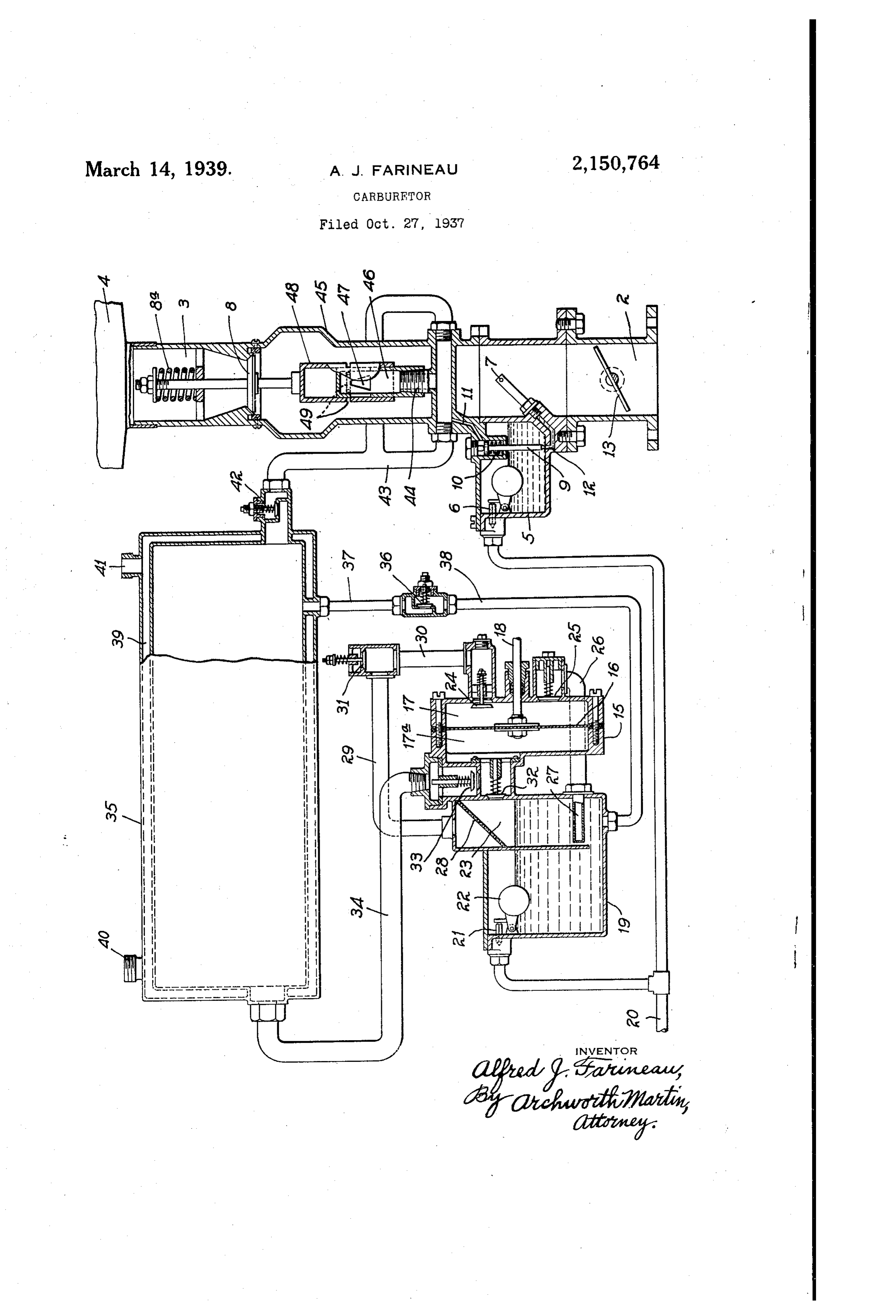
My invention relates to carburetors such as are liquid fuel, the engine is initially started and run employed for supplying a mixture of vaporized for a short period of time through the medium of fuel and air to internal combustion engines. fuel Supplied from the chamber 5. Upon start One object of my invention is to provide a de ing of the engine, the vaporization and compres 5 vice for more effectively vaporizing gasoline or To Sion of the main Supply of motive fuel is begun. this end, I provide a double-acting pump which other liquid fuel, than is possible with various includes types of carburetors heretofore employed, to . pump diaphragm. a chamber or casing 5 containing a thereby effect economy in consumption of fuel, 5 into compartments f6, which divides the chamber and to secure greater uniformity of operation of phragm. f6 is reciprocated7 byand Ta. The dia a rod 18, that is in 10 10 an internal combustion engine to which the fuel is Supplied. turn actuated from any suitable moving part of Another object of my invention is to provide the engine, such as the crank shaft, water or oil means for supplying vaporized fuel to the intake pump shafts, etc. The pump serves to circulate line of an internal combustion engine, at prede air through a body of gasoline contained within s 15 termined pressures. a reservoir f9, and to place the vapor-laden air Still another object of my invention is to pro under pressure. . ? Gasoline or other motive fluid is supplied from vide means for effectively maintaining a constant ratio of fuel and air to the supply line or intake a5. line 20, which may also supply the chamber The gasoline is under pressure, and will enter 20 manifold of an internal combustion engine.
20 The single figure of the drawing is a side view, the reservoir f9 past a valve 2 that is controlled partially in Section, of apparatus embodying my by a float 22, which will maintain a predeter invention. mined level within the reservoir. A bubble com In the drawing, the numeral 2 indicates a fuel ispartment 23 is provided in the reservoir and air intake line leading to the cylinder or manifold to circulated upwardly through this compartment effect vaporization of the fuel. 25 5 of an internal combustion engine (not shown).
Air for the explosive mixture is Supplied through In circulating the air, movement of the pump an intake 3 to which an air cleaner may be ap diaphragm. f6 toward the left will draw air into plied, as indicated at 4. A fuel Supply chamber the compartment 7 of the pump chamber, past an inwardly-opening check valve 24, and will 30 5 is provided for starting and initially running force vapor Out of the compartment Td at the 30 the engine. The fuel level in the chamber 5 is opposite controlled by a float-operated valve 6. Upon the diaphragm side of the diaphragm. Movement of starting of the engine, fuel is drawn from the air out of saidincompartmentthe Opposite direction will force chamber 5 through a jet or spray nozzle 7 and valve 25, from wher.2e it enters a ,pipe past a check 26 leading 35 the suction created in the line 2 will also draw to a nozzle 27 in the lower portion of the bubble 35 air from the intake 3, past a valve 8. Flow of compartment 23, the air being discharged through gasoline to the jet pipe 7 is controlled by a valve the upper perforated portion of the nozle 2. A 9 that is normally held in raised position by a spring fo. Upon development of vaporized fuel perforated baffle plate 28 is provided above the liquid level in the bubble compartment, against 40 pressure within the system, as hereinafter ex Which upWardly-moving drops of fuel will im 40 plained, the valve 9 is automatically closed by pinge. The air passes from the compartment 23 such vapor pressure acting through a port .
When the pressure within the port if reaches a again to a pipe 29 and thence to a pipe 30 where it predetermined degree, the valve 9 will be forced circulation is drawn past the valve 4. Continued down against the pressure spring 0 to close a effective vaporizationof the air in this manner results in of the gasoline. Addi 45 port 2 through which communication is af tional air is automatically drawn in past a check forded between the chamber 5 and the jet pipe 7.
Fuel Supply to the motor is controlled by the usual valve 3,the in accordance with the demands on the throttle waive f3, operated in a suitable or ordi system, valve 3 opening to admit additional air as required when the valve 24 is opened upon nary manner. - 50 50 My invention contemplates that during normal suction stroke of thhe pump diaphragm 6. running of the engine, the explosive mixture theThe pump also serves to withdraw vapor from therefor, shall consist of vaporized gasoline or it tocirculating system just described, and to move a vapor reservoir. To this end, I provide other motive fluid supplied under pressure, and mixed with a suitable quantity of air. In order a check valve 32 located above the liquid level to effect vaporization and compression of the in the bubble chamber 22. Upon movement of 55
Page 3
the diaphragm 6 to the right, vapor will be 47 and the ports 49 will be correspondingly in drawn from the bubble compartment, past this creased.
valve 32 into the compartment fla of the pump It will be understood that the setting of the chamber. Upon movement of the diaphragm to valve 42 is such that it will Open at lower res the left, the body of vapor thus withdrawn will ervoir pressure than will the valve 36. The pump be forced past a check valve 33 into a line 34 is of Sufficient capacity to maintain a desired which leads to a vapor reservoir 35. pressure within the reservoir 35 at maximum The area of the port opening of the valves demands of the engine, so that there will always 24 and 25 is materially greater than the area of be proper proportioning of the vapor and air O port opening of the valve 32, so that there will which forms the combustible mixture. 10 be always a body of vapor moving through the While vaporization could be effected to some circulating system, a portion of which is drawn degree by passing a stream of air only once past the valve 32 and discharged into the reser through a body of gasoline, Such procedure re voir 35. Sufficient air is admitted through the sults in vaporizing only the lighter constituents s valve 3 to replace the vapor thus withdrawn of the gasoline. I have found that by repeatedly from the circulating system. 5 passing a given body of air through the gasoline,
In order that the pressure within the reser it is possible to effect more complete vaporization voir 35 will not exceed a predetermined degree, and to Secure a more richly laden Vapor. I provide a relief valve 36 connected through a claim as my invention: pipe 37 with the vapor reservoir 35 and through 1. Apparatus for forming explosive charges for 20 a pipe 38 with the circulating system. In this internal combustion engines and the like, com case, the vapor thus returned to the circulating prising means for circulating air through a body system will cause a corresponding reduction in of liquid fuel, means for withdrawing the mixture the amount of air admitted through the valve 3. thus produced and placing it under pressure, The reservoir 35 is jacketed to provide a Space means automatically operable when said pressure 39 through which hot water from the engine attains a predetermined degree for directing the cooling system or exhaust gases may be circu compressed mixture into an air stream, and lated in order to heat the vapor and prevent con means for varying the volume of mixture supplied densation thereof. Inlet and outlet openings. 40 and 4 are provided for circulating the heating to the air stream in accordance with changes in
medilm. 2. Apparatus for forming explosive charges for When the body of vapor within the reservoir internal combustion engines and the like, com 35 becomes built up to a predetermined preSSure, prising means for creating flow of air through a it will move a valve 42 from its seat and flow body of liquid fuel, a pump for compressing the through a branched line or conduit 3 to an mixture thus produced, a reservoir for receiving outlet 44 located within a metering chamber 45, the compressed mixture, an air conduit, means interposed between the air inlet 3 and the pas actuated by pressure in the reservoir for control sageway 2. The outlet 44 discharges into a sleeve 46 that has valve openings 4 of gen ling flow from the reservoir to said conduit, a valve for controlling the flow of air in said con erally triangular form. Discharge through the duit, and means controlled by movement of said O openings 47 is controlled by a sleeve member 8 valve for varying the rate at which the com which has telescopic movement with respect to pressed mixture flows from the reservoir into the the member 46 and is provided with discharge air stream.
ports 49 in its sides. When the ports 49 are 3. Apparatus for forming explosive charges for brought into registry with the ports 47, vapor will flow from reservoir 35 into the metering cham prising acombustion internal engines and the like, com fuel intake line for an engine, means ber 45. It will be seen that as the vapor under pressure enters the pipe 43, a portion thereof operative through suction in said line for effecting discharge of a jet of liquid fuel into the line, will flow through the port if and cut of flow of 50 gasoline from the chamber 5 to the spray head means for effecting flow of air through a body of 7, thereby automatically transferring the source liquid thus fuel, means for compressing the mixture 50 produced, means for directing the com of supply of combustible fuel from the chamber pressed mixture into said intake line, and means 5 to the reservoir 35, or in other words, from the actuated by the mixture when compressed to a
liquid source to the vapor source. predetermined degree, for shutting off the first It will be understood that under idling cond named Supply of fuel to the said line. ? 55 tions of the engine, with the throttle valve 3 4. Apparatus for forming explosive charges for in nearly closed position, the intake suction will internal combustion engines, comprising a fuel be of a low degree and the valve 8 drawn only intake line for an engine, means for effecting dis a short distance from its seat, against the pres charge of liquid fuel into said line, means for sure of a spring 8a. The valve 8 has its stem producing a vaporized mixture of air and liquid 60 connected to the valve member 48, so that as the fuel, means for compressing said mixture and valve 8 moves down, the ports 49 of the valve forcing it into said line, and means actuated by member 48 will be brought into registry with the the compressed mixture, for shutting off the said ports 47, whereupon fuel vapor will flow into the discharge of liquid fuel.
5. Apparatus for forming explosive charges for air stream and be carried to the engine manifold.
There need, of course; be only a Small Supply of internal combustion engines and the like, com prising a pump operable in predetermined rela fuel vapor during idling, and since the upper tion to engine speed, for circulating air through ends of the ports 45 are of narrow width, they a body of liquid fuel and placing under pressure 70 will be uncovered to only a small extent at idling stage. At greater throttle openings, as under the mixture of fuel and air thus produced, means for directing the said compressed mixture into an driving conditions, the valve 8 will be drawn far air stream to form an explosive mixture, an air ther from its seat, and as the valve member 48 intake for the pump, and means automatically is thereby moved downwardly, the area of port Operable when the pressure of said fuel mixture 75 opening as between the triangularly shaped ports exceeds a predetermined degree, for directing a
Page 4
of fuel and air, and means automatically operable portion of said mixture to the pump, to thereby when the said pressure falls below a predeter reduce the amount of air admitted to the pump mined point, for shutting of flow of the fuel mix and control the pressure of said mixture of fuel ture to the air stream.
and air. 7. Apparatus for forming explosive charges for 6. Apparatus for forming explosive charges for internal combustion engines and the like, com internal combustion engines and the like, corn prising means for circulating air through a body prising a pump operable in predetermined rela of liquid fuel, means for withdrawing the mixture tion to engine speed, for circulating air through thus produced and placing it under pressure, a body of liquid fuel and placing under pressure means for directing the compressed mixture into 10 O the mixture of fuel and air thus produced, means an air stream, means for varying the volume of for directing the said compressed mixture into mixture supplied to the air stream, in accord an air stream to form an explosive mixture, an ance with changes in air flow, and means auto air intake for the pump, means automatically matically operable by said pressure, independently operable when the pressure of said fuel mixture of said varying means, for controlling the flow of 5 .
exceed a predetermined degree, for directing a the mixture into the air stream. portion of said fuel mixture to the pump, to thereby reduce the amount of air admitted to the ALFRED J. FARINEAU. pump and control the pressure of said mixture
Provenance
- Collection
- Cited prior art
- Original PDF
- patentimages.storage.googleapis.com →
- Filed
- 1937-10-27
- Pages
- 4
- Method
- pdftotext (the PDF's own text layer) + pdftoppm 300dpi page scans
- Source
- Google Patents bibliographic record
- Granted
- 1939-03-14
- Inventors
- Alfred J Farineau; RALPH C COREY; RICHARD M KUHN
- Transcribed from
- patentimages.storage.googleapis.com →