patent · US5012945
Rupture disk assembly
7 May 1991
Page 1 — bibliographic record
United States Patent (19) 11 Patent Number: 5,012,945 Keenan 45) Date of Patent: May 7, 1991 (54 RUPTURE DISK ASSEMBLY 4,793,509 12/1988 Coleman . 4,796,704 l/1989 Forrest .................................. 137/70 75) Inventor: Gordon A. Keenan, Baton Rouge, La.
73) Assignee: Exxon Research and Engineering Co. OTHER PUBLICATIONS (21 Appl. No.: 450,967 U.S. Coast Guard Drawing (by Appl. Admission 1 yr. Prior to Filing).
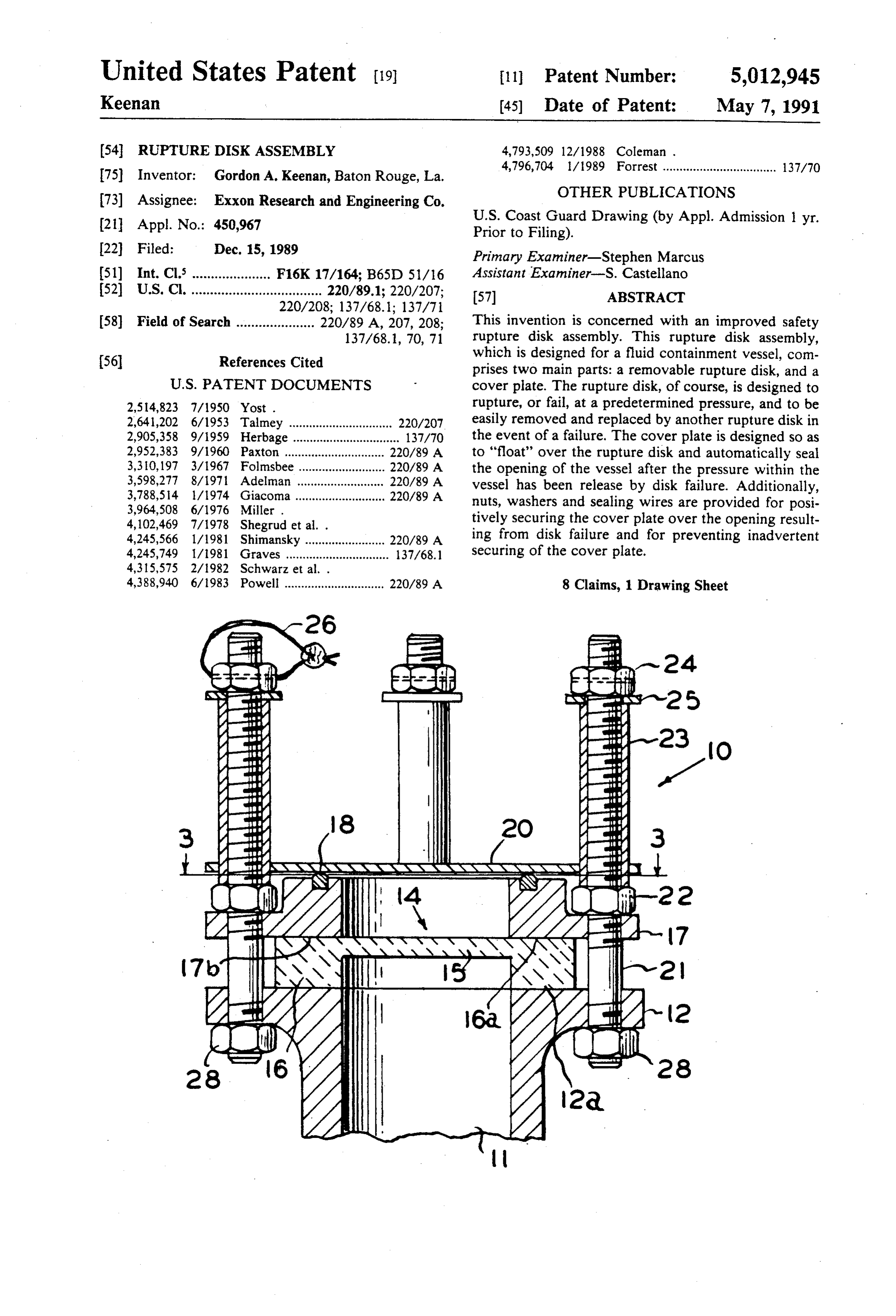
22 Filed: Dec. 15, 1989 Primary Examiner-Stephen Marcus 51) Int. Cl...................... F16K 17/164; B65D 51/16 Assistant Examiner-S. Castellano 52 U.S. C. ................................... 220/89.1; 220/207; 57 ABSTRACT
58) Field of Search ..................... 220/89 A, 207, 208; This invention is concerned with an improved safety 137/68.1, 70, 71 rupture disk assembly. This rupture disk assembly, (56) References Cited which is designed for a fluid containment vessel, com prises two main parts: a removable rupture disk, and a
2,514,823 7/1950 Yost . rupture, or fail, at a predetermined pressure, and to be 2,641,202 6/1953 Talmey ............................... 220/207 easily removed and replaced by another rupture disk in 2,905,358 9/1959 Herbage ................................ 137/70 the event of a failure. The cover plate is designed so as 2,952,383 9/1960 Paxton .............................. 220/89 A to "float" over the rupture disk and automatically seal 3,310, 197 3/1967 Folmsbee.......................... 220/89 A the opening of the vessel after the pressure within the 3,598,277 8/1971 Adelman .......................... 220/89 A vessel has been release by disk failure. Additionally, 3,788,54 l/1974 Giacoma ........................... 220/89 A nuts, washers and sealing wires are provided for posi
4,102,469 7/1978 Shegrud et al. . tively securing the cover plate over the opening result 4,245,566 1/1981 Shimansky ........................ 220/89 A ing from disk failure and for preventing inadvertent 4,245,749 1/1981 Graves ............................... 137/68.1 securing of the cover plate.
4,388,940 6/1983 Powell .............................. 220/89 A 8 Claims, 1 Drawing Sheet
2- El-23
E. E. O
3 N 2Si:* NRNA NRNA NAAS SAF
SNSXS
Page 2
Drawing sheet — no readable text.
Page 3
designed to rupture, or fail, at a predetermined pressure,
RUPTURE DISKASSEMBLY and to be easily removed and replaced by another rup
FIELD OF THE INVENTION
ture disk in the event of a failure. The cover plate is designed so as to "float' over the rupture disk and auto
The present invention relates generally to safety pres matically seal the opening of the vessel after the pres sure relief devices and, more particularly, to improved sure within the vessel has been released by disk failure. ruptured disk assembly for use with fluid containment Additionally, means are provided for positively secur vessels used in closed loading service. ing the cover plate over the opening resulting from disk BACKGROUND OF THE INVENTION failure and for preventing inadvertent securing of the 10 cover plate.
Fluid containment vessels generally are fitted with These and other features of the invention will be best pressure relief devices that will automatically vent the understood from the detailed description which follows vessel to the atmosphere when a maximum permissible when read in conjunction with the accompanying pressure level is reached within the vessel, thus prevent 15 drawings.
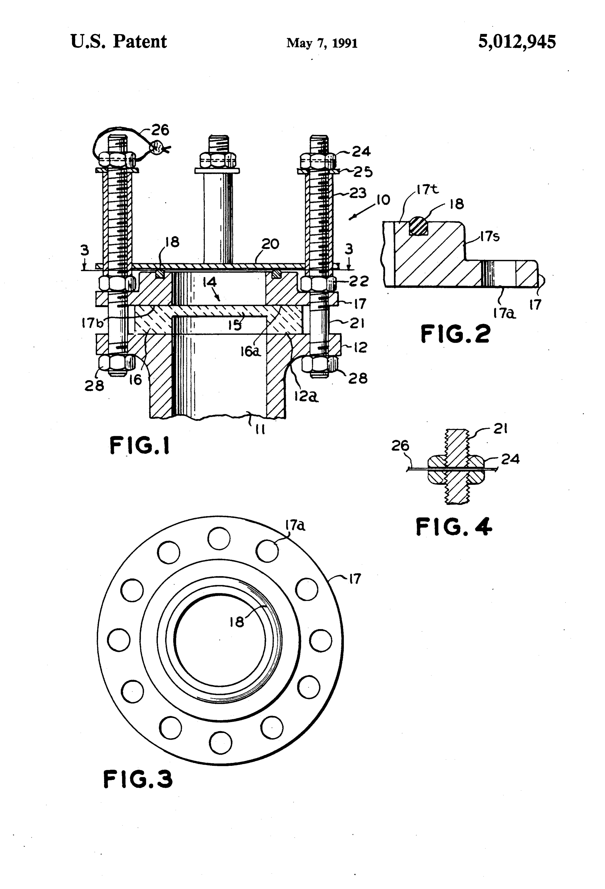
ing failure of the vessel. For example, barges used for transporting liquids have fluid containment hulls that BRIEF DESCRIPTION OF THE DRAWINGS are not designed to withstand pressures greater than FIG. 1 is a vertical cross-sectional view of a rupture about 3.0 psi. Consequently, it has long been the prac disk assembly according to the present invention. tice to provide safety vents on the barge, which will automatically open to the atmosphere when pressure of 20 theFIG. 2 is a fragmentary cross-sectional view showing shoulder of the top flange illustrated in FIG. 1.
the fluid containment barge vessel reaches a maximum FIG. 3 is a plan view, taken along lines 3-3 of FIG. permissible pressure. w 1, of the top flange of the assembly of FIG. 1 showing An example of one type of pressure relief device used the bolt apertures in the top flange. on containment vessels can be found in U.S. Pat. No. FIG. 4 is a detailed illustration of the sealing wire 3,310,197. This device consists essentially of a rupture 25 aperture in the bolt and nut shown in FIG. 1. disk which is covered by a non-sealable but pivotably mounted cap to keep dirt and foreign material off the DETAILED DESCRIPTION OF THE disk. If the disk is ruptured, the tank cannot be posi INVENTION tively sealed without replacing the ruptured disk.
In U.S. Pat. No. 3,598,277, there is disclosed a safety 30 shown mounted on a1,tubular
Referring to FIG. the rupture disk assembly 10 is relief valve that includes a rupture disk and a closure containment vessel (not shown).tank vent 11 of a fluid Vent 11, as shown, has cap. The closure cap is mounted in such a way that it can move vertically upward, permitting communication a mounting flange 12. The rupture disk assembly 10 of the tank with the atmosphere in the event of the includes a rupture disk 14 having a central portion 15 failure of the rupture disk. The cap can move vertically 35 with a diameter sufficient to cover the opening in vent downward so as to close the opening in the tank when 11 and an annular ring portion 16 that bears on the top, the pressure in the tank is reduced to approximately flat, annular sealing face 12a of mounting flange 12. atmospheric pressure. The disadvantage of such a de The rupture disk 14 can be fabricated from any of a vice, however, is that it does not positively seal the tank number of well known materials. The disk 14, of course, contents from the atmosphere. Indeed, if the contents of 40 is made to rupture at a predetermined pressure. In gen the tank have a relatively high vapor pressure, the eral, the material used for the construction of the rup vapor would tend to lift the cap. ture disk 14 will be a material which is inert to the fluid Other devices that have been employed as safety to be contained in the fluid vessel. In the practice of the valves include spring loaded, and weighted covers for present invention, it is particularly preferred that the the tank openings. In some instances, these devices have 45 rupture disk be made from carbon, graphite or other also been-provided with bolting devices for positively inert and high temperature resistant material that can be sealing the cover when the containment vessel is formed, for example, by compression molding or the loaded. The disadvantage of these types of devices, of like. This type of rupture disk is commercially available. course, is that the cover may inadvertently be secured Optionally, the rupture disk can be coated with prior to filling of the container, thereby preventing the 50 chemical inert films and the like. assembly from relieving pressure, if necessary, with the The rupture disk assembly 10 of the present invention result that the safety feature of the assembly is lost. also includes an annular top flange 17 having a bottom Accordingly, there remains a need for an improved face 17b which bears on the top surface 16a of disk 14. rupture disk assembly that will prevent excessive pres Top flange 17 includes a plurality of apertures 17a sure from developing in liquid containment vessels, 55 which are spaced so as to align with corresponding especially during closed loading service, which will apertures in mounting flange 12. In the practice of the possess self-closing ability after rupture, thereby auto present invention, it is preferred that there be at least matically sealing the tank contents from the atmo four, and more preferably at least 12, apertures equally sphere. Finally, also, there is a need for a rupture disk spaced around the periphery of annular top flange 17, as assembly that can be positively sealed but which will well as corresponding apertures equally spaced along not readily lend itself to being inadvertently secured. the mounting flange 12.
SUMMARY OF THE INVENTION As can be seen particularly in FIG. 2, the top flange 17 has a shoulder portion 17s, having a top surface 17t. It
Accordingly this invention is concerned with an im is particularly preferred in the practice of the present proved safety rupture disk assembly. This rupture disk 65 invention that the top surface 17t is machined with a assembly, which is designed for a fluid containment groove parallel to that face to accommodate a portion vessel, comprises two main parts: a removable rupture of an O-ring 18. The O-ring, of course, serves as a seal disk, and a cover plate. The rupture disk, of course, is ing gasket and may be fabricated from any resilient
Page 4
material, such as rubbers, elastomers and the like. Alter barge with the possible loss of the entire tank contents natively, other flexible gasketing means may be inter into the surrounding environment. After the disk 14 posed between the cover plate 20 and the top surface ruptures, cover 20 will float upwardly guided by the 17t of flange 17. stud bolts 21 covered with the riding sleeves 23. As As can be seen in FIG. 1, a floating cover plate 20 is soon as the reason for overpressurization of the tank is horizontally disposed over annular top flange 17. The corrected, the cover 20 will move vertically downward cover plate 20 is provided with a plurality of apertures, and sit on the O-ring 18 thereby positively sealing the preferably four, equally spaced in an annular ring so contents of the tank from the atmosphere. Additionally, that they will align with corresponding apertures in the before getting underway, the sleeves 23 can be removed top flange 17 and the mounting flange 12. O and the nuts 24 urged downwardly, thereby securing A plurality of stud bolts 21, equal in number to the apertures in cover plate 20, are provided, which have theBycover 20 in place during shipment of the cargo. equipping the rupture disk assembly 10 with a bodies sized to extend through the apertures in the sealing wire 26, that wire must be broken in order to mounting flange 12, the top flange 17 and cover plate 20 when the ruptured disk 14 is in position in the assembly 15 secure vertent cover plate 20 in position, thereby avoiding inad securing of the cover plate 20, which would, of 10. Studbolts 21 have a length that is sufficient to act as vertical guides for floating cover plate 20. In general, course, As negate the safety feature of the rupture disk 14.
will be readily apparent, the rupture disk assembly the length of the studbolts will be about 2 to 3 times the 10 of the present invention also permits a ruptured disk distance from the bottom of mounting flange 12 to the 14 to be readily changed in a matter of minutes by the top of cover plate 20 when disk 14 is in position in the 20 assembly 10 and preferably in the range of about 2.3 to operator. Thus, the rupture disk assembly of the present about 2.5 times that distance. invention has numerous advantages, among which are A plurality of first nuts 22 are positioned on studbolts the fact that it provides protection against overpressur 21 below the cover plate 20 and above top flange 17 and ization of fluid containment tank. It has a self-closing a plurality of second nuts 28 are positioned on studbolts 25 ability because the cover plate will automatically seal 21 below mounting flange 12, so that when the first nuts the tank from the atmosphere after the ruptured disk has 22 are tightened, they urge the top flange 17 down been ruptured and the pressure has been released from wardly onto the top surface 16a of the annular ring the tank. It has a significant safety feature in that the position 16 of ruptured disk 14. Optionally, other fasten cover plate cannot be inadvertently secured, thereby ing and guiding means can be employed, such as elon 30 overriding the effectiveness of the rupture disk. Addi gated bolts having a fixed head at one end obviating the tionally the assembly is readily disassembled and re necessity for second nuts 28. paired. These and other significant advantages of the A riding sleeve 23 is positioned on each of the stud device of the present invention should be readily appar bolts 21 above the nuts 22, so that cover plate 20 is ent to those with skill in the art to which this subject capable of moving upwardly and downwardly in a 35 matter pertains, vertical direction without being encumbered in any Also, it should be understood that while certain forms way by the threads on the bolts 21. of this invention have been illustrated and described, it A second set of nuts 24 are positioned on the distal is not to be limited thereto, except insofar as such limita end of bolts 21 so as to maintain the riding sleeve 23 in tions are included in the following claims. position and prevent vertical movement of sleeves 23. What is claimed is:
Optionally and preferably, a plurality of washers 25 are 1. A rupture disk assembly for mounting on a tubular interposed between top of the riding sleeves 23 and the vent of a fluid containment vessel comprising: second set of nuts 24.
In the event the mounting flange 12 and top flange 17 a replaceable rupture disk for horizontal mounting are provided with more than four apertures, for exam 45 a top over the tubular vent;
ple 12 apertures as shown in FIG. 3, additional bolts flange means positioned over the rupture disk; may be provided for tightening the top flange 17 onto securing means for urging the top flange down the mounting flange 12. These bolts, of course, will not wardly and securing the rupture disk over the tu extend upward above the top surface 17t of flange 17 bular vent thereby sealing the fluid in the vessel from and preferably will be of a length that the top of these 50 a vertically the atmosphere;
bolts will be sufficiently below the top surface 17t of moveable cover plate horizontally dis flange 17 so that the bolts will not interfere with cover posed over and resting on the top flange; plate 20 seating on flange 17. means for guiding the vertical movement of the cover In a particularly preferred embodiment of the present plate whereby the cover plate will move vertically invention, at least one of the stud bolts 21 has an aper 55 upward upon failure of the rupture disk caused by ture at the distal end of sufficient size to accommodate an increase in pressure in the fluid containment a sealing wire. Additionally, a nut 24 placed on that stud vessel above a predetermined pressure, thereby bolt 21 has an aperture through which, when in align relieving the increased pressure and the cover plate ment with the aperture in bolt 12, will permit a sealing will move vertically downward and seal the vent wire 26 to extend through the nut and bolt. 60 when the pressure is relieved; When the rupture disk assembly is arranged and in means for securing the cover plate over the top flange stalled as shown in FIG. 1, for example on a fluid cargo after a failure of the rupture disk; and, tank of an inland water barge, the tank can be filled a sealing wire operatively connected to the means for without the fluid being exposed to the atmosphere. In securing the cover plate whereby the sealing wire the event, however, that the tank becomes overpressu 65 must be broken before the cover plate can be se rized, for example by overfilling or the like, the disk 14 cured over the top flange by the means for securing will rupture, thereby relieving the pressure within the the plate thereby preventing inadvertent securing tank thereby preventing a catastrophic failure of the of the cover plate.
Page 5
2. The assembly of claim 1 including a flexible sealing lar ring portion of the rupture disk, the top flange gasket means interposed between the cover plate and having an outer annular ring portion with apertures the top flange. therein spaced to be in alignment with the aper 3. The assembly of claim 2 wherein the top flange has tures in the bottom flange;
a top surface and an annular groove in the top surface a plurality of bolts extending upwardly through the and wherein the flexible gasket means is an O-ring posi top and bottom flange for a distance substantially tioned in the groove. greater than the vertical height of the bottom 4. The assembly of claim 1 wherein the means for flange, rupture disk and top flange; urging the top flange downwardly on the rupture disk is a plurality of nuts on the blots for urging the top a plurality of nuts and bolts wherein the top flange has O flange downwardly on the annular ring portion of a plurality of apertures therein and the bolts extend the rupture disk whereby the rupture disk is vertically through the apertures for a sufficient distance mounted over the tubular vent of the containment to serve as the means for guiding the vertical movement vessel;
of the cover plate. a vertically moveable cover plate horizontally dis 5. The assembly of claim 4 wherein the cover plate 15 posed over the top flange, the cover plate having a has a plurality of apertures therein which are aligned plurality of apertures therein spaced to align with with the apertures in the top flange to permit the bolts the apertures in the top and bottom flanges; that extend vertically through the apertures in the top annular gasket means interposed between the cover flange to pass through the apertures in the cover plate plate and the top surface of the inner annular ring wherein the bolts guide the vertical movement of the 20 portion of the top flange; cover plate. a plurality of second nuts mounted on the end of the 6. The assembly of claim 5 wherein the bolts are bolts for securing the cover plate onto the top provided with riding sleeves on the portion of the bolts flange whereby the cover plate can move verti above the top flange whereby the cover plate can move cally upward upon a failure of the rupture disk vertically without being hindered by bolt threads. 25 resulting from excessive pressure in the fluid con 7. A rupture disk assembly for mounting on a tubular tainment vessel and then vertically downward to vent of a fluid containment vessel comprising: seal the vessel upon release of the excessive pres a bottom flange for mounting on the tubular vent of sure and whereby the plurality of second nuts can the containment vessel, the flange having an inner be moved downward on the bolts to secure the annular top sealing surface and an outer annular 30 cover; and, part having a plurality of evenly spaced apertures a sealing wire operatively connected to the means for therethrough; securing the cover plate whereby the sealing wire a replaceable rupture disk having a central portion must be broken before the cover plate can be se capable of rupturing at a predetermined pressure cured over the top flange by the means for securing and an annular ring portion having a top surface 35 the plate thereby preventing inadvertent securing and a bottom surface, the annular ring sized so that of the cover plate.
its bottom surface bears on the top sealing surface 8. The assembly of claim 7 wherein the top surface of of the bottom flange; the inner annular ring portion of the top flange includes a top flange having an inner annular ring portion an annular groove and wherein the gasket means is an having a top and a bottom surface, the inner ring 40 O-ring adapted to fit in the annular groove. portion sized to bear on the top surface of the annu k k
Provenance
- Collection
- Cited prior art
- Original PDF
- patentimages.storage.googleapis.com →
- Filed
- 1989-12-15
- Pages
- 5
- Method
- pdftotext (the PDF's own text layer) + pdftoppm 300dpi page scans
- Source
- Google Patents bibliographic record
- Granted
- 1991-05-07
- Inventors
- Gordon A. Keenan; Exxon Research and Engineering Co
- Transcribed from
- patentimages.storage.googleapis.com →