patent · US4953514
Device for the metered supplying of fuel vapor into the intake pipe of a combustion engine
4 September 1990
Page 1 — bibliographic record
United States Patent (19) 11 Patent Number: 4,953,514 Beicht et al. 45 Date of Patent: Sep. 4, 1990 (54) DEVICE FOR THE METERED SUPPLYING 4,628,887 12/1986 Mitchell .............................. 123/520 OF FUEL WAPOR INTO THE INTAKE PPE 4,671,240 6/1987 Tanaka . ... 23/463 OFA COMBUSTON ENGINE 4,703,737 11/1987 Cook ..... ... 123/520 4,763,635 8/1988 Ballhause ............................ 123/520 (75) Inventors: Bernd Beicht, Gross-Umstadt; 4,809,667 3/1989 Uranishi .............................. 123/520 Reinhard Tinz, Gross-Bieberau; 4,865,000 9/1989 Yajima ................................ 123/458 Joachin Heinemann, Weinheim, all 4,872,439 10/1989 Sonoda ................................ 123/519 of Fed. Rep. of Germany 4,901,902 2/1990 Deicht et al. ....................... 123/458 73) Assignee: Firma Carl Freudenberg, Primary Examiner-Carl Stuart Miller Weinheim/Bergstr., Fed. Rep. of Attorney, Agent, or Firm-Felfe & Lynch
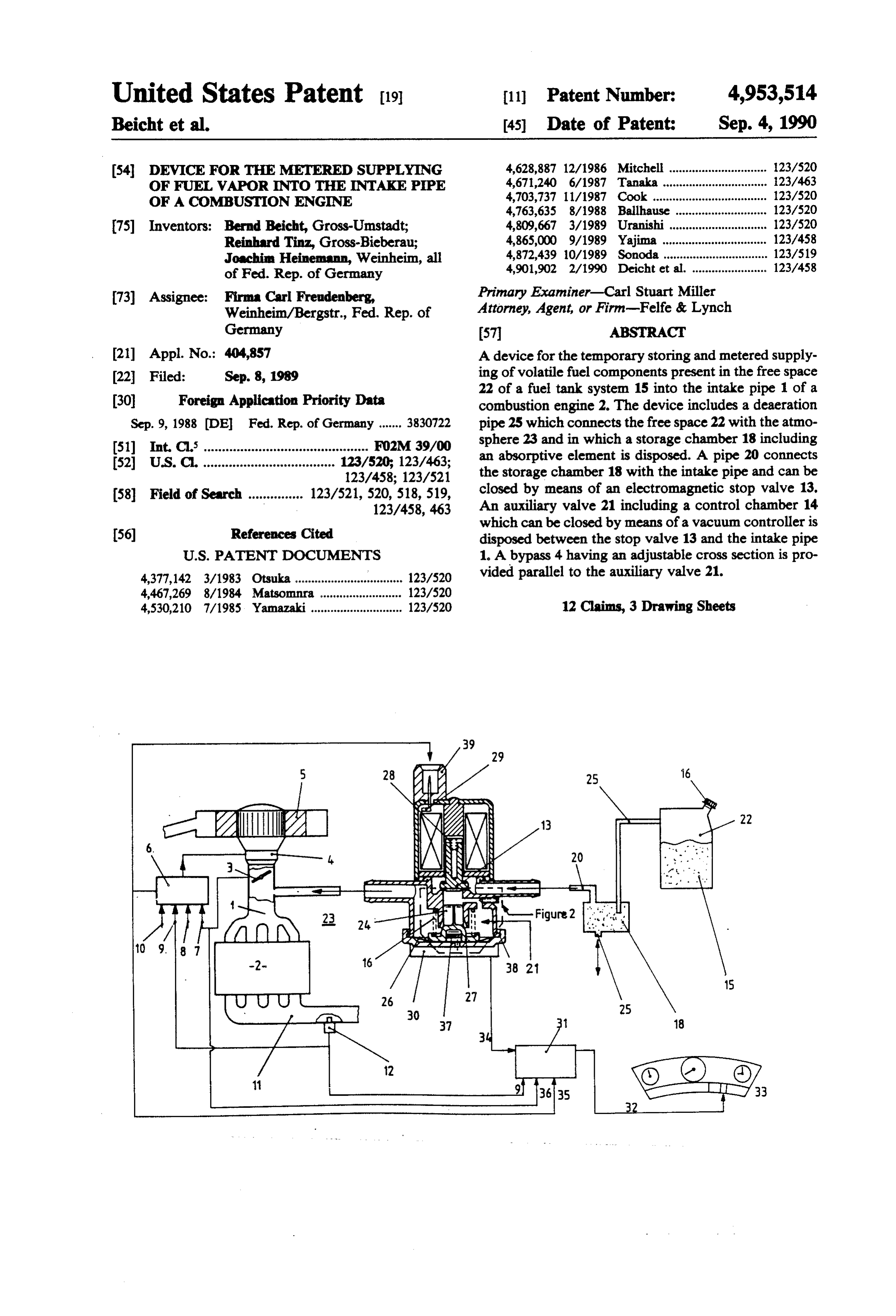
Germany 57 ABSTRACT 21 Appl. No.: 404,857 A device for the temporary storing and metered supply (22 Filed: Sep. 8, 1989 ing of volatile fuel components present in the free space (30) Foreign Application Priority Data 22 of a fuel tank system 15 into the intake pipe 1 of a combustion engine 2. The device includes a deaeration
Sep. 9, 1988 (DE Fed. Rep. of Germany ....... 3830722 pipe 25 which connects the free space 22 with the atmo 51) Int, C. ............................................. FO2M 39/00 sphere 23 and in which a storage chamber 18 including 52 U.S. C. .................................... 123/520; 123/463; an absorptive element is disposed. A pipe 20 connects 123/458; 123/521 the storage chamber 18 with the intake pipe and can be 58 Field of Search ............... 123/521,520, 518, 519, closed by means of an electromagnetic stop valve 13. 123/458, 463 An auxiliary valve 21 including a control chamber 14
which can be closed by means of a vacuum controller is disposed between the stop valve 13 and the intake pipe
4,377,142 3/1983 Otsuka ................................. 123/520 vided parallel to the auxiliary valve 21. 4,467,269 8/1984. Matsoninra ... ... 123/520 4,530,210 7/1985 Yamazaki ............................ 123/520 12 Claims, 3 Drawing Sheets
2 NSSs KY
aaaaa
Page 2
Drawing sheet — no readable text.
Page 3
Drawing sheet — no readable text.
Page 4
Drawing sheet — no readable text.
Page 5
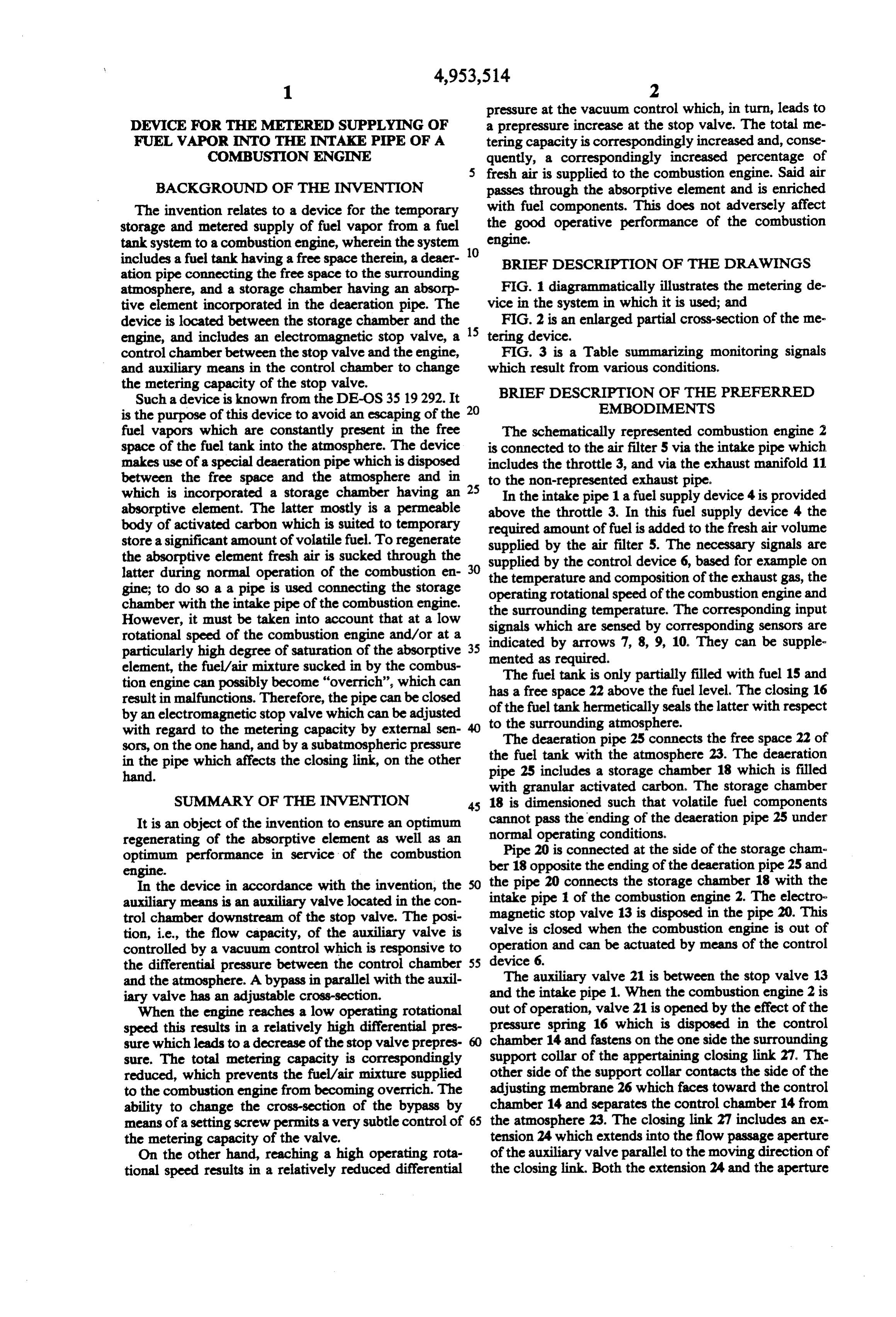
pressure at the vacuum control which, in turn, leads to
DEVICE FOR THE METERED SUPPLYING OF a prepressure increase at the stop valve. The total me FUEL WAPOR INTO THE INTAKE PPE OFA tering capacity is correspondingly increased and, conse COMBUSTON ENGINE quently, a correspondingly increased percentage of fresh air is supplied to the combustion engine. Said air
BACKGROUND OF THE INVENTION passes through the absorptive element and is enriched The invention relates to a device for the temporary with fuel components. This does not adversely affect storage and metered supply of fuel vapor from a fuel the good operative performance of the combustion tank system to a combustion engine, wherein the system 10 engine.
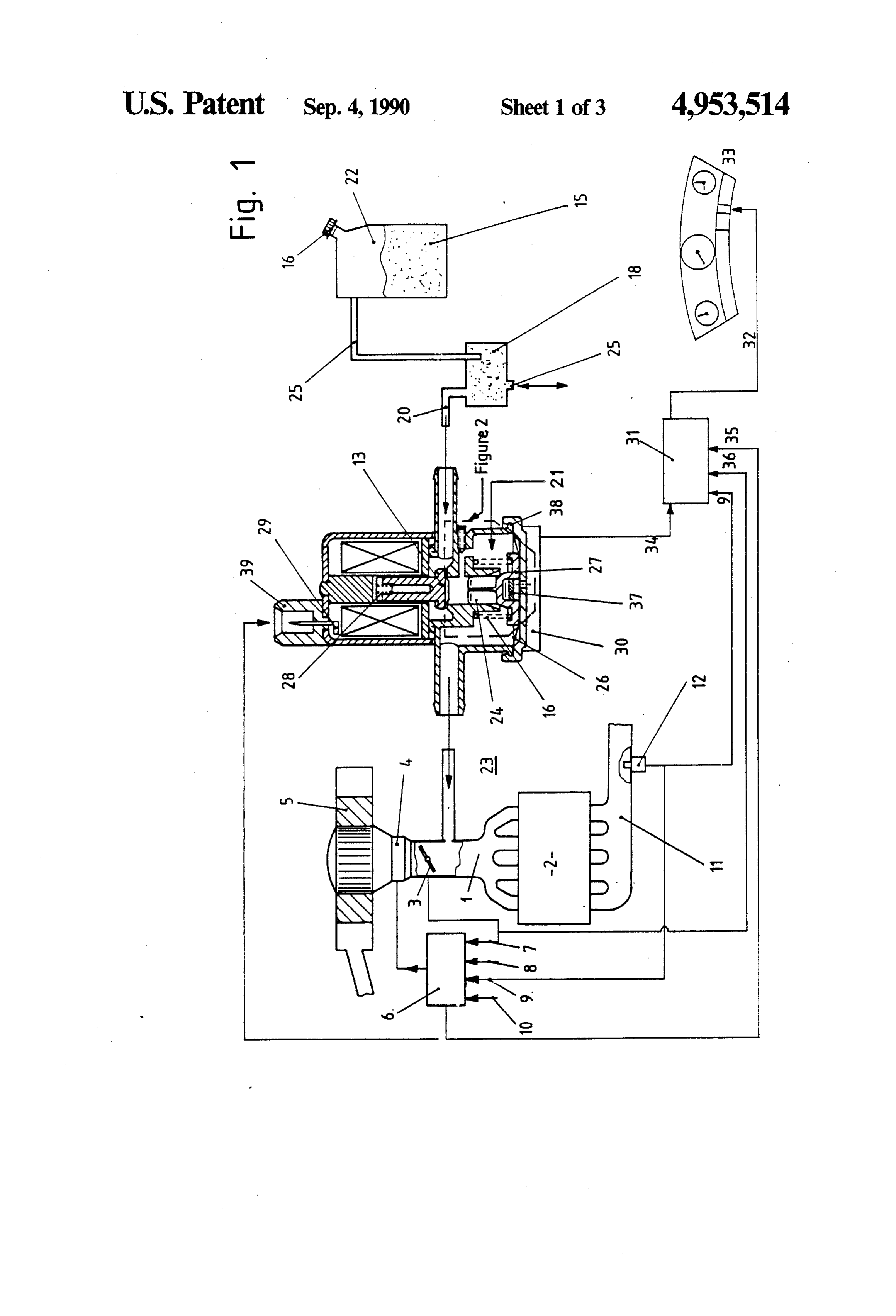
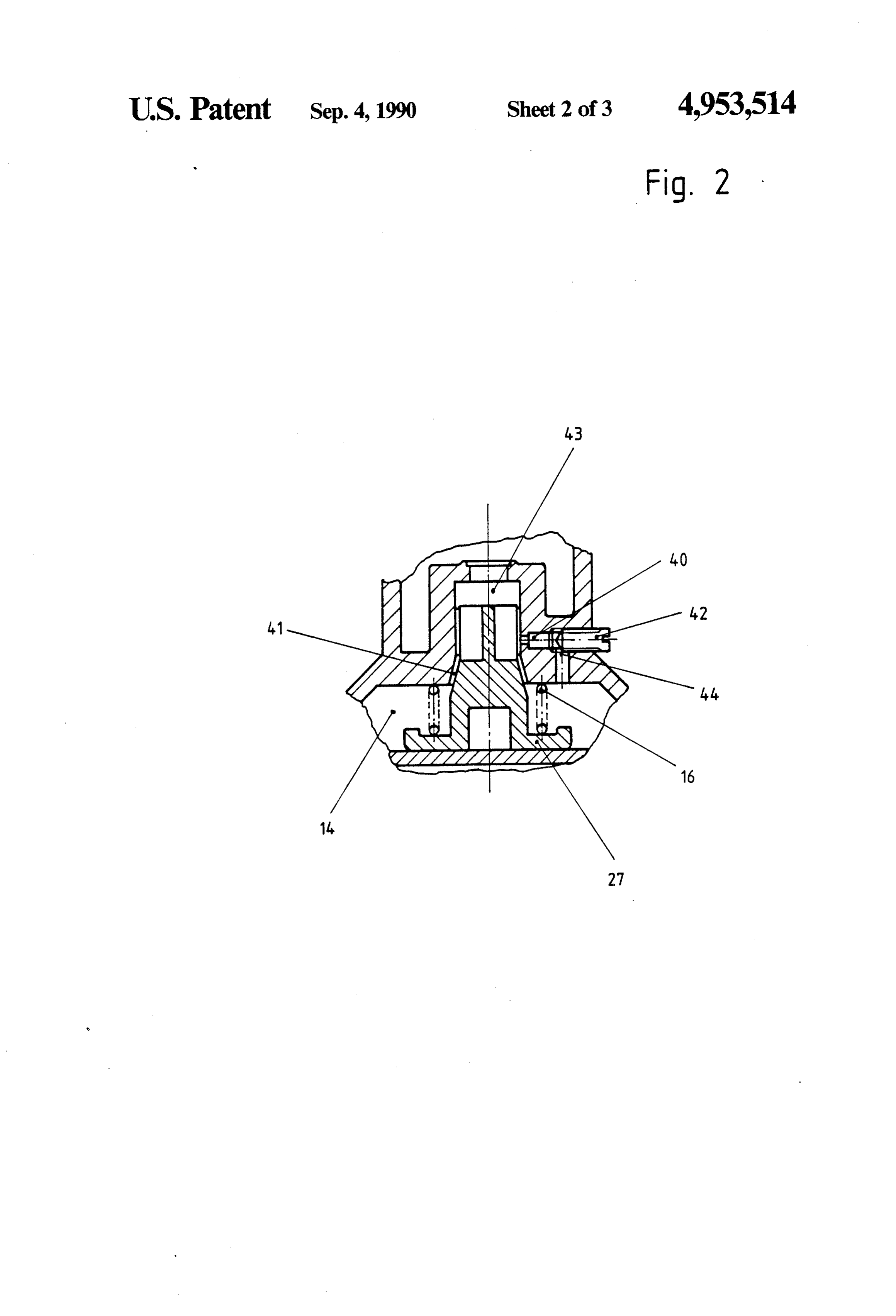
includes a fuel tank having a free space therein, a deaer BRIEF DESCRIPTION OF THE DRAWINGS ation pipe connecting the free space to the surrounding atmosphere, and a storage chamber having an absorp FIG. 1 diagrammatically illustrates the metering de tive element incorporated in the deaeration pipe. The vice in the system in which it is used; and device is located between the storage chamber and the 15 FIG. 2 is an enlarged partial cross-section of the me engine, and includes an electromagnetic stop valve, a tering device.
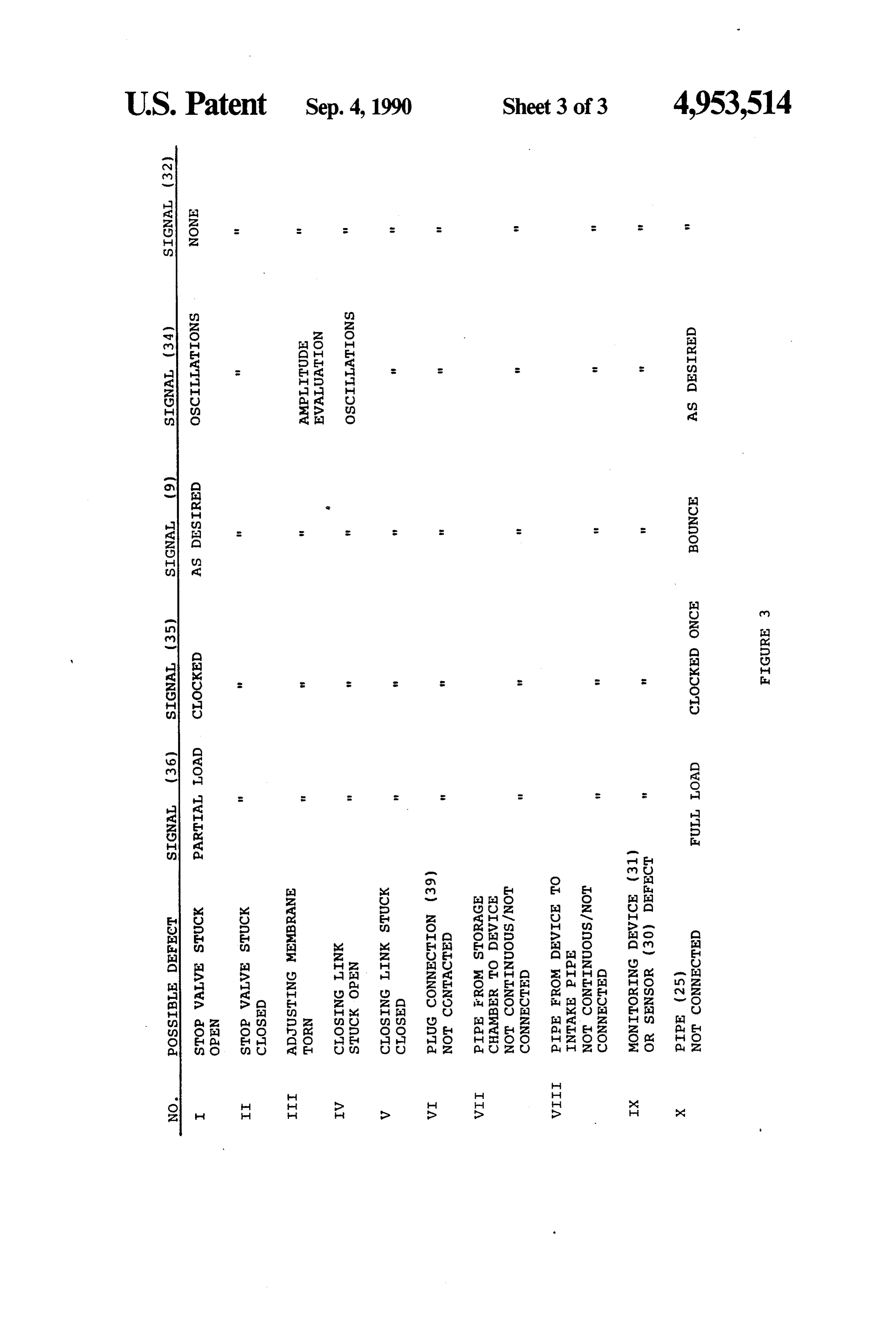
control chamber between the stop valve and the engine, FIG. 3 is a Table summarizing monitoring signals and auxiliary means in the control chamber to change which result from various conditions. the metering capacity of the stop valve. BRIEF DESCRIPTION OF THE PREFERRED Such a device is known from the DE-OS 35 19292. It is the purpose of this device to avoid an escaping of the 20 EMBODIMENTS fuel vapors which are constantly present in the free The schematically represented combustion engine 2 space of the fuel tank into the atmosphere. The device is connected to the air filter 5 via the intake pipe which makes use of a special deaeration pipe which is disposed includes the throttle 3, and via the exhaust manifold 11 between the free space and the atmosphere and in 25 to the non-represented exhaust pipe.
which is incorporated a storage chamber having an In the intake pipe 1 a fuel supply device 4 is provided absorptive element. The latter mostly is a permeable above the throttle 3. In this fuel supply device 4 the body of activated carbon which is suited to temporary required amount of fuel is added to the fresh air volume store a significant amount of volatile fuel. To regenerate supplied by the air filter 5. The necessary signals are the absorptive element fresh air is sucked through the supplied by the control device 6, based for example on latter during normal operation of the combustion en 30 temperature and composition of the exhaust gas, the gine; to do so a a pipe is used connecting the storage the operating rotational speed of the combustion engine and chamber with the intake pipe of the combustion engine. the surrounding temperature. The corresponding input However, it must be taken into account that at a low signals which are sensed by corresponding sensors are rotational speed of the combustion engine and/or at a indicated by arrows 7, 8, 9, 10. They can be supple particularly high degree of saturation of the absorptive 35 element, the fuel/air mixture sucked in by the combus mented The as required.
fuel tank is only partially filled with fuel 15 and tion engine can possibly become "overrich', which can has a free space 22 above the fuel level. The closing 16 result in malfunctions. Therefore, the pipe can be closed by an electromagnetic stop valve which can be adjusted of the fuel tank hermetically seals the latter with respect with regard to the metering capacity by external sen to The the surrounding atmosphere. deaeration pipe 25 connects the free space 22 of sors, on the one hand, and by a subatmospheric pressure the fuel tank with the atmosphere 23. The deaeration in the pipe which affects the closing link, on the other pipe 25 includes hand. a storage chamber 18 which is filled with granular activated carbon. The storage chamber
SUMMARY OF THE INVENTION 45 18 is dimensioned such that volatile fuel components It is an object of the invention to ensure an optimum cannot pass the ending of the deaeration pipe 25 under regenerating of the absorptive element as well as an normal operating conditions.
optimum performance in service of the combustion berPipe 20 is connected at the side of the storage cham 18 opposite the ending of the deaeration pipe 25 and engine.
In the device in accordance with the invention, the the pipe 20 connects the storage chamber 18 with the auxiliary means is an auxiliary valve located in the con intake pipe 1 of the combustion engine 2. The electro trol chamber downstream of the stop valve. The posi magnetic stop valve 13 is disposed in the pipe 20. This tion, i.e., the flow capacity, of the auxiliary valve is valve is closed when the combustion engine is out of controlled by a vacuum control which is responsive to operation and can be actuated by means of the control the differential pressure between the control chamber 55 device 6.
and the atmosphere. A bypass in parallel with the auxil The auxiliary valve 21 is between the stop valve 13 iary valve has an adjustable cross-section. and the intake pipe 1. When the combustion engine 2 is When the engine reaches a low operating rotational out of operation, valve 21 is opened by the effect of the speed this results in a relatively high differential pres pressure spring 16 which is disposed in the control sure which leads to a decrease of the stop valve prepres chamber 14 and fastens on the one side the surrounding sure. The total metering capacity is correspondingly support collar of the appertaining closing link 27. The reduced, which prevents the fuel/air mixture supplied other side of the support collar contacts the side of the to the combustion engine from becoming overrich. The adjusting membrane 26 which faces toward the control ability to change the cross-section of the bypass by chamber 14 and separates the control chamber 14 from means of a setting screw permits a very subtle control of 65 the atmosphere 23. The closing link 27 includes an ex the metering capacity of the valve. tension 24 which extends into the flow passage aperture On the other hand, reaching a high operating rota of the auxiliary valve parallel to the moving direction of tional speed results in a relatively reduced differential the closing link. Both the extension 24 and the aperture
Page 6
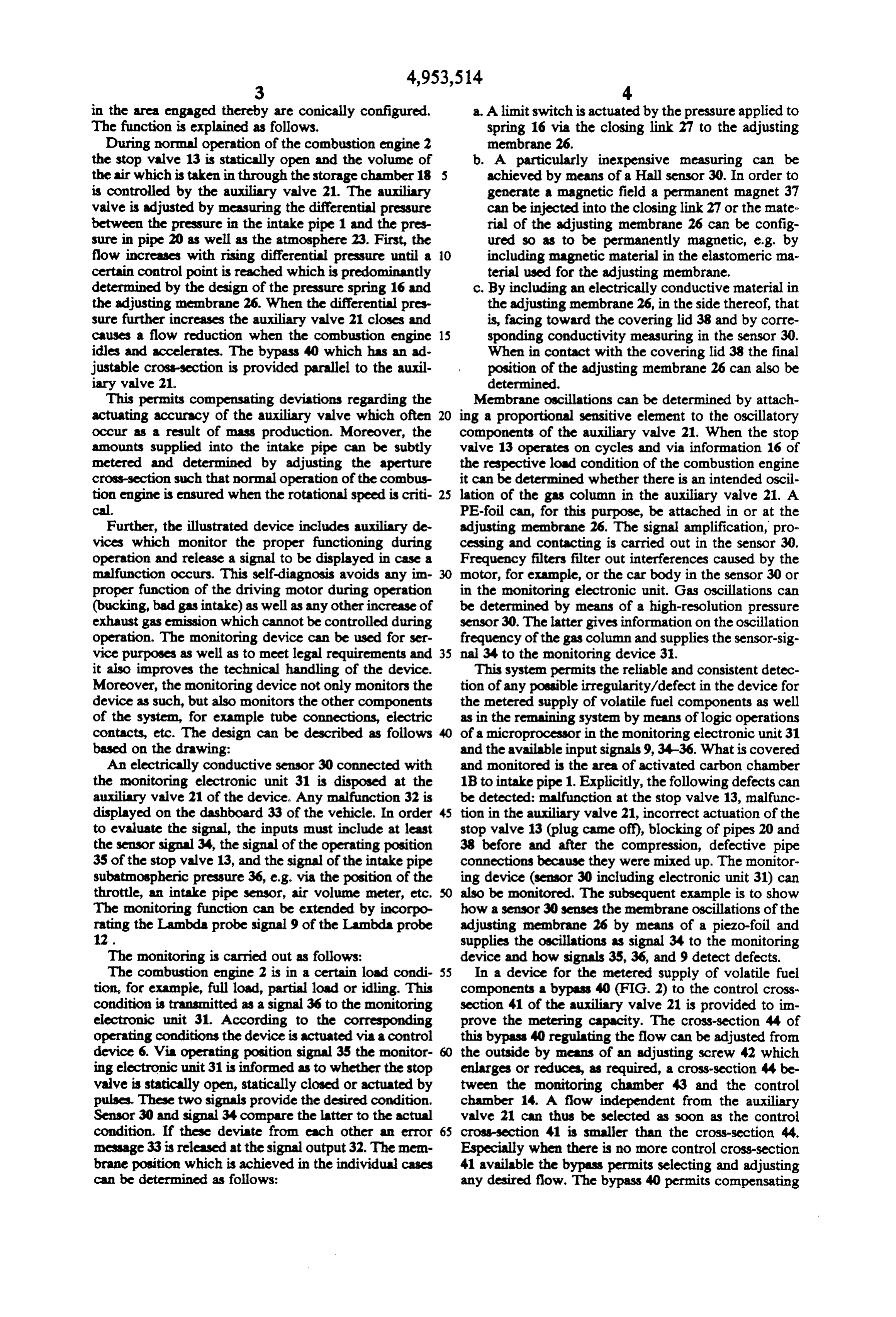
in the area engaged thereby are conically configured. a. A limit switch is actuated by the pressure applied to The function is explained as follows. spring 16 via the closing link 27 to the adjusting During normal operation of the combustion engine 2 membrane 26.
the stop valve 13 is statically open and the volume of b. A particularly inexpensive measuring can be the air which is taken in through the storage chamber 18 5 achieved by means of a Hall sensor 30. In order to is controlled by the auxiliary valve 21. The auxiliary generate a magnetic field a permanent magnet 37 valve is adjusted by measuring the differential pressure can be injected into the closing link 27 or the mate between the pressure in the intake pipe 1 and the pres rial of the adjusting membrane 26 can be config sure in pipe 20 as well as the atmosphere 23. First, the ured so as to be permanently magnetic, e.g. by flow increases with rising differential pressure until a O including magnetic material in the elastomeric na certain control point is reached which is predominantly terial used for the adjusting membrane. determined by the design of the pressure spring 16 and . By including an electrically conductive material in the adjusting membrane 26. When the differential pres the adjusting membrane 26, in the side thereof, that sure further increases the auxiliary valve 21 closes and is, facing toward the covering lid 38 and by corre causes a flow reduction when the combustion engine 15 sponding conductivity measuring in the sensor 30. idles and accelerates. The bypass 40 which has an ad When in contact with the covering lid 38 the final justable cross-section is provided parallel to the auxil position of the adjusting membrane 26 can also be iary valve 21. determined.
This permits compensating deviations regarding the Membrane oscillations can be determined by attach actuating accuracy of the auxiliary valve which often ing a proportional sensitive element to the oscillatory occur as a result of mass production. Moreover, the components of the auxiliary valve 21. When the stop amounts supplied into the intake pipe can be subtly valve 13 operates on cycles and via information 16 of metered and determined by adjusting the aperture the respective load condition of the combustion engine cross-section such that normal operation of the combus it can be determined whether there is an intended oscil tion engine is ensured when the rotational speed is criti 25 lation of the gas column in the auxiliary valve 21. A cal. PE-foil can, for this purpose, be attached in or at the Further, the illustrated device includes auxiliary de adjusting membrane 26. The signal amplification, pro vices which monitor the proper functioning during cessing and contacting is carried out in the sensor 30. operation and release a signal to be displayed in case a Frequency filters filter out interferences caused by the malfunction occurs. This self-diagnosis avoids any in 30 motor, for example, or the car body in the sensor 30 or proper function of the driving motor during operation in the monitoring electronic unit. Gas oscillations can (bucking, bad gas intake) as well as any other increase of be determined by means of a high-resolution pressure exhaust gas emission which cannot be controlled during sensor 30. The latter gives information on the oscillation operation. The monitoring device can be used for ser frequency of the gas column and supplies the sensor-sig vice purposes as well as to meet legal requirements and 35 nal 34 to the monitoring device 31. it also improves the technical handling of the device. This system permits the reliable and consistent detec Moreover, the monitoring device not only monitors the tion of any possible irregularity/defect in the device for device as such, but also monitors the other components the metered supply of volatile fuel components as well of the system, for example tube connections, electric as in the remaining system by means of logic operations contacts, etc. The design can be described as follows of a microprocessor in the monitoring electronic unit 31 based on the drawing: and the available input signals 9,34-36. What is covered An electrically conductive sensor 30 connected with and monitored is the area of activated carbon chamber the monitoring electronic unit 31 is disposed at the 1B to intake pipe 1. Explicitly, the following defects can auxiliary valve 21 of the device. Any malfunction 32 is be detected: malfunction at the stop valve 13, malfunc displayed on the dashboard 33 of the vehicle. In order 45 tion in the auxiliary valve 21, incorrect actuation of the to evaluate the signal, the inputs must include at least stop valve 13 (plug came off), blocking of pipes 20 and the sensor signal 34, the signal of the operating position 38 before and after the compression, defective pipe 35 of the stop valve 13, and the signal of the intake pipe connections because they were mixed up. The monitor subatmospheric pressure 36, e.g. via the position of the ing device (sensor 30 including electronic unit 31) can throttle, an intake pipe sensor, air volume meter, etc. also be monitored. The subsequent example is to show The monitoring function can be extended by incorpo how a sensor 30 senses the membrane oscillations of the rating the Lambda probe signal 9 of the Lambda probe adjusting membrane 26 by means of a piezo-foil and 12. supplies the oscillations as signal 34 to the monitoring The monitoring is carried out as follows: device and how signals 35, 36, and 9 detect defects. The combustion engine 2 is in a certain load condi 55 In a device for the metered supply of volatile fuel tion, for example, full load, partial load or idling. This components a bypass 40 (FIG. 2) to the control cross condition is transmitted as a signal 36 to the monitoring section 41 of the auxiliary valve 21 is provided to im electronic unit 31. According to the corresponding prove the metering capacity. The cross-section 44 of operating conditions the device is actuated via a control this bypass 40 regulating the flow can be adjusted from device 6. Via operating position signal 35 the monitor the outside by means of an adjusting screw 42 which ing electronic unit 31 is informed as to whether the stop enlarges or reduces, as required, a cross-section 44 be valve is statically open, statically closed or actuated by tween the monitoring chamber 43 and the control pulses. These two signals provide the desired condition. chamber 14. A flow independent from the auxiliary Sensor 30 and signal 34 compare the latter to the actual valve 21 can thus be selected as soon as the control condition. If these deviate from each other an error cross-section 41 is smaller than the cross-section 44. message 33 is released at the signal output 32. The mem Especially when there is no more control cross-section brane position which is achieved in the individual cases 41 available the bypass permits selecting and adjusting can be determined as follows: any desired flow. The bypass 40 permits compensating
Page 7
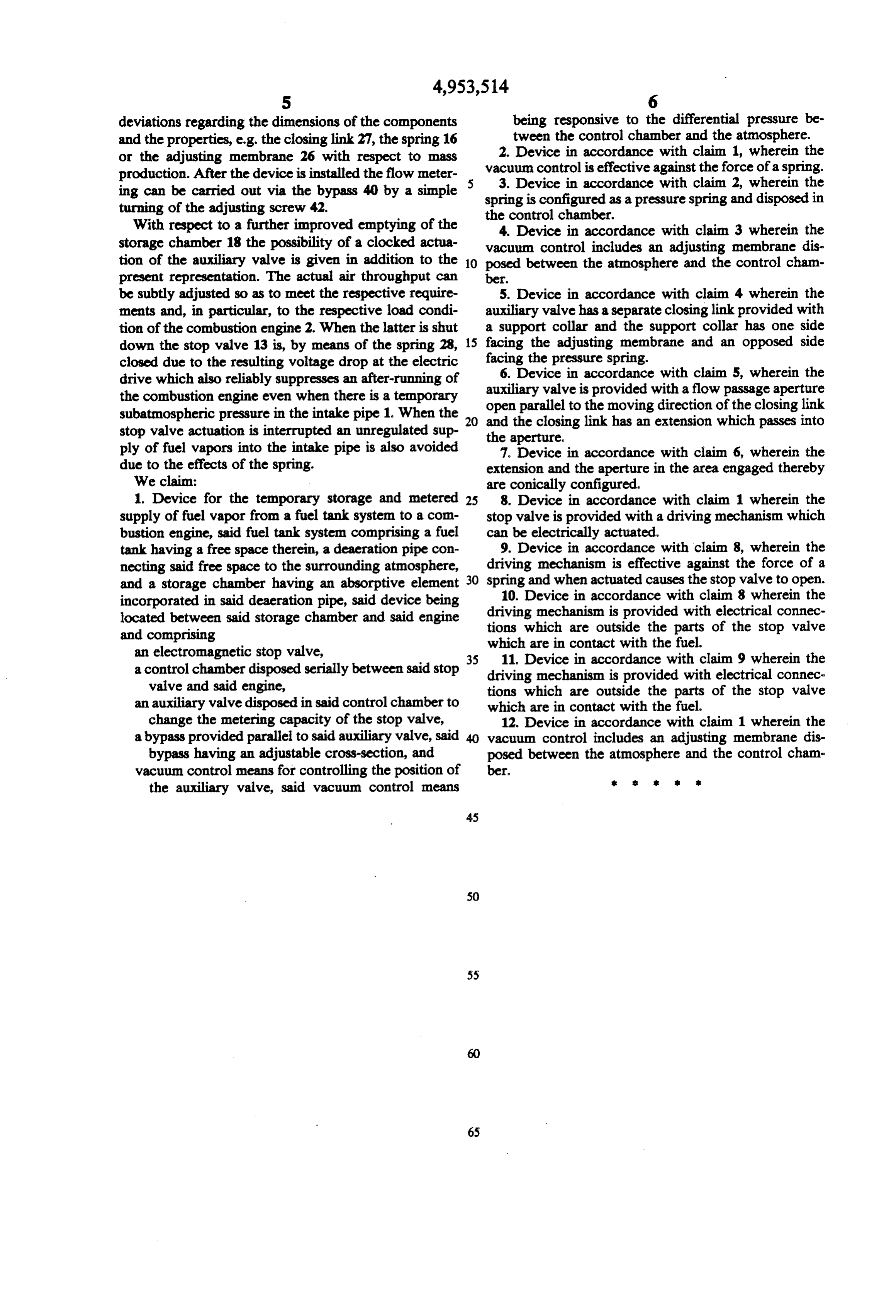
deviations regarding the dimensions of the components being responsive to the differential pressure be and the properties, e.g. the closing link 27, the spring 16 tween the control chamber and the atmosphere. or the adjusting membrane 26 with respect to mass 2. Device in accordance with claim 1, wherein the production. After the device is installed the flow meter vacuum control is effective against the force of a spring. ing can be carried out via the bypass 40 by a simple 3. Device in accordance with claim 2, wherein the turning of the adjusting screw 42. spring is configured as a pressure spring and disposed in With respect to a further improved emptying of the the4.control chamber.
Device in accordance with claim 3 wherein the storage chamber 18 the possibility of a clocked actua vacuum control includes an adjusting membrane dis tion of the auxiliary valve is given in addition to the 10 posed between the atmosphere and the control cham present representation. The actual air throughput can ber.
be subtly adjusted so as to meet the respective require 5. Device in accordance with claim 4 wherein the ments and, in particular, to the respective load condi auxiliary valve has a separate closing link provided with tion of the combustion engine 2. When the latter is shut a support collar and the support collar has one side down the stop valve 13 is, by means of the spring 28, 15 facing the adjusting membrane and an opposed side closed due to the resulting voltage drop at the electric facing the pressure spring.
6. Device in accordance with claim 5, wherein the drive which also reliably suppresses an after-running of auxiliary the combustion engine even when there is a temporary open parallel valve is provided with a flow passage aperture subatmospheric pressure in the intake pipe 1. When the 20 and the closingto the moving direction of the closing link stop valve actuation is interrupted an unregulated sup the aperture. link has an extension which passes into ply of fuel vapors into the intake pipe is also avoided 7. Device in accordance with claim 6, wherein the due to the effects of the spring. extension and the aperture in the area engaged thereby We claim: are conically configured.
1. Device for the temporary storage and metered 25 8. Device in accordance with claim 1 wherein the supply of fuel vapor from a fuel tank system to a com stop valve is provided with a driving mechanism which bustion engine, said fuel tank system comprising a fuel can be electrically actuated.
tank having a free space therein, a deaeration pipe con 9. Device in accordance with claim 8, wherein the necting said free space to the surrounding atmosphere, driving mechanism is effective against the force of a and a storage chamber having an absorptive element 30 spring and when actuated causes the stop valve to open. incorporated in said deaeration pipe, said device being 10. Device in accordance with claim 8 wherein the located between said storage chamber and said engine driving mechanism is provided with electrical connec tions which are outside the parts of the stop valve and comprising which are in contact with the fuel. an electromagnetic stop valve, 35 11. Device in accordance with claim 9 wherein the a control chamber disposed serially between said stop driving mechanism is provided with electrical connec valve and said engine, tions which are outside the parts of the stop valve an auxiliary valve disposed in said control chamber to which are in contact with the fuel. change the metering capacity of the stop valve, 12. Device in accordance with claim 1 wherein the a bypass provided parallel to said auxiliary valve, said 40 vacuum control includes an adjusting membrane dis bypass having an adjustable cross-section, and posed between the atmosphere and the control cham vacuum control means for controlling the position of ber.
the auxiliary valve, said vacuum control means
Page 8
UNITED STATES PATENT AND TRADEMARK OFFICE
CERTIFICATE OF CORRECTION
NVENTOR(S) : Beicht et al.
it is certified that error appears in the above-identified patent and that said Letters Patent is hereby corrected as shown below:
Column 2, line 22, after "pipe" insert --1--.
Signed and Sealed this
Twenty-ninth Day of September, 1992
Attest:
DOUGLAS B. COMER
Attesting Officer Acting Commissioner of Patents and Trademarks
Provenance
- Collection
- Cited prior art
- Original PDF
- patentimages.storage.googleapis.com →
- Filed
- 1989-09-08
- Pages
- 8
- Method
- pdftotext (the PDF's own text layer) + pdftoppm 300dpi page scans
- Source
- Google Patents bibliographic record
- Granted
- 1990-09-04
- Inventors
- Bernd Beicht; Reinhard Tinz; Joachim Heinemann; Carl Freudenberg KG
- Transcribed from
- patentimages.storage.googleapis.com →