patent · US4820033
Solar mirror apparatus
11 April 1989
Page 1 — bibliographic record
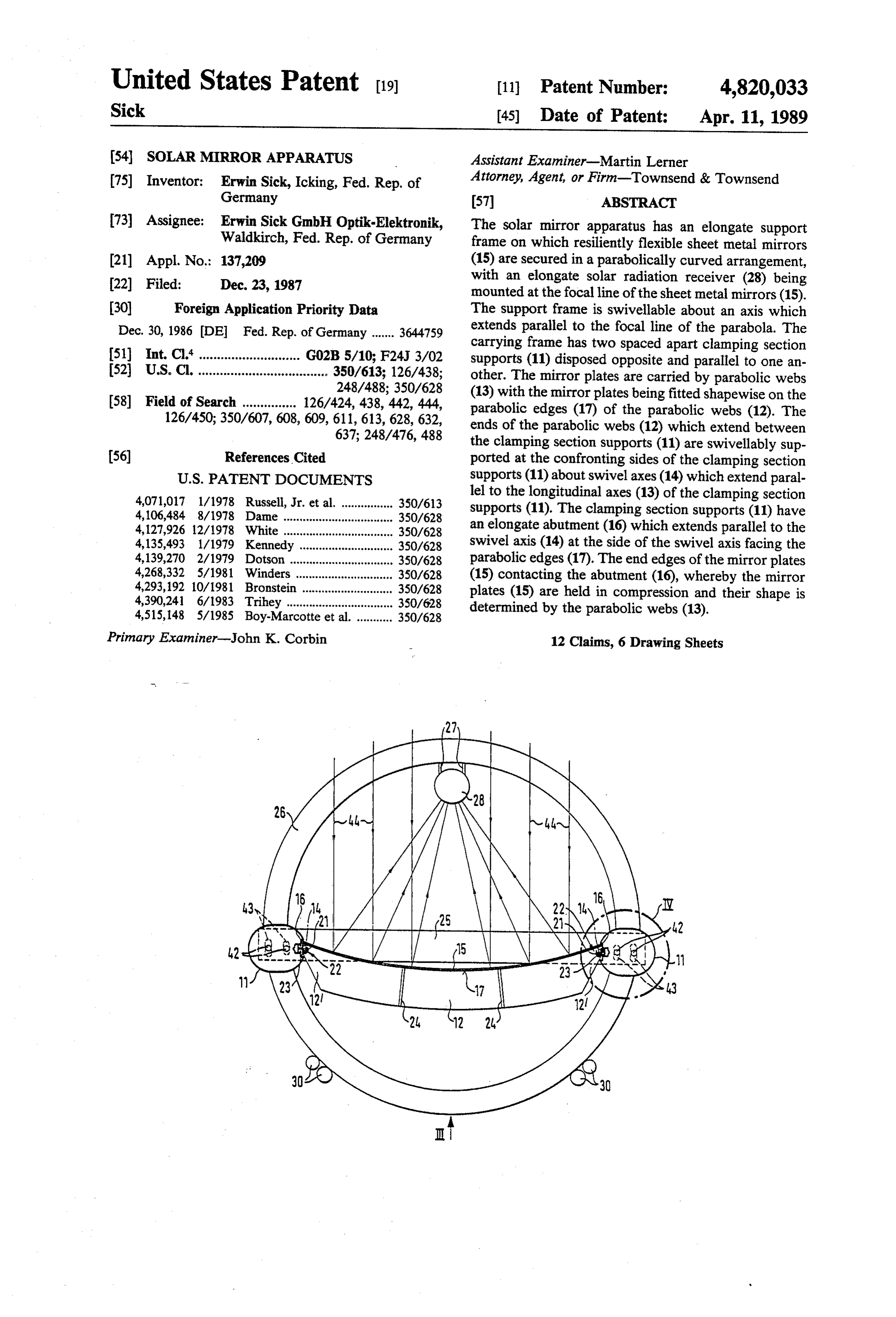
United States Patent (19) (11)Patent Number: 4,820,033 Sick 45) Date of Patent: Apr. 11, 1989 54). SOLAR MIRROR APPARATUS Assistant Examiner-Martin Lerner (75) Inventor: Erwin Sick, Icking, Fed. Rep. of Attorney, Agent, or Firm-Townsend & Townsend Germany (57) ABSTRACT 73) Assignee: Erwin Sick GmbH Optik-Elektronik, The solar mirror apparatus has an elongate support Waldkirch, Fed. Rep. of Germany frame on which resiliently flexible sheet metal mirrors (21) Appl. No.: 137,209 (15) are secured in a parabolically curved arrangement, 22 Filed: Dec. 23, 1987 with an elongate solar radiation receiver (28) being mounted at the focal line of the sheet metal mirrors (15).
(30) Foreign Application Priority Data The support frame is swivellable about an axis which Dec. 30, 1986 (DE Fed. Rep. of Germany ....... 3644759 extends parallel to the focal line of the parabola. The carrying frame has two spaced apart clamping section 51 Int. Cl." ............................ G02B 5/10; F24J 3/02 supports (11) disposed opposite and parallel to one an 52 U.S. Cl. .................................... 350/613; 126/438: other. The mirror plates are carried by parabolic webs 248/488; 350/628 (13) with the mirror plates being fitted shapewise on the 58) Field of Search ............... 126/424, 438, 442, 444, parabolic edges (17) of the parabolic webs (12). The 126/450; 350/607, 608, 609, 611, 613, 628, 632, ends of the parabolic webs (12) which extend between 637; 248/476, 488 the clamping section supports (11) are swivellably sup (56) References Cited ported at the confronting sides of the clamping section
4,071,017 1/1978 Russell, Jr. et al. ................ 350/613 lel to the longitudinal axes (13) of the clamping section 4,106,484 8/1978 Dame .............. ... 350/628 supports (11). The clamping section supports (11) have 4,127,926 12/1978 White ...... ... 350/628 an elongate abutment (16) which extends parallel to the 4,135,493 1/1979 Kennedy. ... 350/628 swivel axis (14) at the side of the swivel axis facing the 4,139,270 2/1979 Dotson ... ... 350/628 parabolic edges (17). The end edges of the mirror plates 4,268,332 5/1981 Winders ...... ... 350/628 (15) contacting the abutment (16), whereby the mirror 4,293,192 10/1981 Bronstein ... ... 350/628 plates (15) are held in compression and their shape is 4,390,241 6/1983 Trihey ......... ... 350/628 determined by the parabolic webs (13). 4,515,148 5/1985 Boy-Marcotte et ... 350/628
Primary Examiner-John K. Corbin 12 Claims, 6 Drawing Sheets
Page 2
Drawing sheet — no readable text.
Page 3
Drawing sheet — no readable text.
Page 4
Drawing sheet — no readable text.
Page 5
Drawing sheet — no readable text.
Page 6
Drawing sheet — no readable text.
Page 7
Drawing sheet — no readable text.
Page 8
SOLAR MERRORAPPARATUS parabolic webs in form fitted manner. In order to bring about this form fitted contact in simple manner, i.e. to make the installation and dismantling of the mirror
The invention relates to a solar mirror apparatus plates as easy as possible, clamping section supports are comprising an elongate carrying frame on which there are secured a parabolically curved arrangement of elas used which make it possible to simply lay in place the tically flexible mirror plates, in particular sheet metal mately plates, mirror which have initially been only approxi curved in parabolic manner, with the compres mirrors, and an elongate radiation receiver disposed at sion of the mirror plates and the form shaped contact the focal line of the mirror plates, with the arrangement with the parabolic edges of parabolic webs then taking being swivellable about an axis extending parallel to the 10 place during subsequent pivoting of the clamping sec focal line of the parabola. tion supports, with the parabolic webs having been Such solar mirror arrangements are in particular used previously pivotally connected to the clamping section in sunny countries for the exploitation of solar energy. supports. On inserting the non-precurved mirror plates Large area mirror arrangements are necessary in order to generate as much energy as possible. The manufac 15 these will be bent as a result of their own weight into a provisional parabolic shape.
ture of such mirror arrangements is however associated A practical realisation of the concept underlying the with considerable expense. invention provides that the clamping section support The principle object underlying the present invention should have an essentially hollow cylindrical basic is thus to provide a solar mirror arrangement of the shape and should have a groove-like cut-out at the side initially named kind with which large area sunlight 20 which supports the mirror plates, with one of the corner receiving surfaces can be realized at low weight and edges of the groove-like cut-out forming the abutment. with an optical quality which is as high as possible, With this arrangement provision should in particular be without the expense and complexity involved in the made that the clamping section support has an elongate manufacture of the solar mirror arrangement being excessively high. In particular components should be 25 slot at its side which supports the mirror surfaces, with sliders which support a pivot bearing defining the used as far as possible which are available in price swivel axis being longitudinally displaceably held in the worthy form in the market place, without the optical longitudinal slot. The longitudinal slot is preferably quality of the mirror arrangement, i.e. the exactness of located at the center of the groove-like cut-out, at the the concentration of the sunlight onto the solar re base thereof.
ceiver, being impaired. Moreover, the mirror plates 30 Futhermore, it is advantageous for the sliders to be should be capable of being exchanged and replaced by fixable in any position along the clamping section sup new ones in simple manner in the event of damage, or of ports. In this manner the sliders can be displaced after them becoming dirty, or otherwise impaired. In opera installation of the clamping section supports to the posi tion the solar mirror arrangement should be stable and operationally reliable even over long periods of opera 35 tion where the parabolic webs are to be arranged to support the mirror plates, and can be fixed there.
tion and when exposed to considerable temperature A practical embodiment is characterized in that a differences between day and night. swivel trunnion connected to the ends of a parabolic In order to solve this problem the invention provides that the carrying frame has two spaced apart clamping web engages into the rotary bearing. With this arrange ment it is in particularly expedient when the rotary section supports disposed opposite and parallel to one bearing and the swivel pin can be clamped against one another; that the mirror plates are carried by parabolic another, essentially in the direction of the tangent to the webs with the mirror plates being fitted shapewise on parabolic surface at this point, in that direction in which the parabolic edges of the parabolic webs; that the ends the end edge of the mirror plate can be pressed to a of the parabolic webs which extend between the clamp greater ing section supports are swivellably supported at the 45 manner aorfine lesser degree against the abutment. In this adjustment of the arrangement of the ends confronting sides of the clamping section supports of the parabolic webs relative to the clamping section about swivel axes which extend parallel to the longitu carriers is possible, with this relative clamping being dinal axes of the clamping section supports; that the most expediently effected via an adjustment screw clamping section supports have an elongate abutment threaded into the rotary bearing.
which extends parallel to the swivel axis at the side of 50 As each individual parabolic web is a relatively unsta the swivel axis facing the parabolic edges, with the end edges of the mirror plates contacting the abutments, ble ing structure in its own right, in particular against bend in its plane, a further development of the invention whereby the mirror plates are held in compression; and provides that in each case two neighbouring parabolic that by releasing and swivelling the or each clamping webs which are arranged spaced apart, are connected section support about the swivel axis the abutment can 55 together by connection webs to form a constructional be released from the end edges.
The concept underlying the invention has thus to be unit. In this way box-like profiled structures are formed which have a very high inherent stability, which is seen in the fact that resiliently flexible structures, in further increased on mounting them on the clamping particular sheet metal mirrors are used as the mirror section supports. The parabolic webs and the mirror plates which from the outset do not have any defined plates are stabilized by mutually clamping or bracing surface-shape. The parabolic surface is on the contrary them together via the clamping section supports. achieved in accordance with the invention by the para bolic edges of the very narrow parabolic webs which is A particularly expedient constructional embodiment characterized in that the two clamping section sup are arranged at suitable spacings alongside one another ports are supplemented at said two ends by connection on the support frame, with the mirror plates being 65 members into a frame, with the connection between the pressed against the parabolic edges of the parabolic clamping section supports and the connection members webs, in the sense of being compressed, in such a way that the mirror plates contact the parabolic edges of the being releasable and being laid out in such a way that the clamping section supports are pivotable about the
Page 9
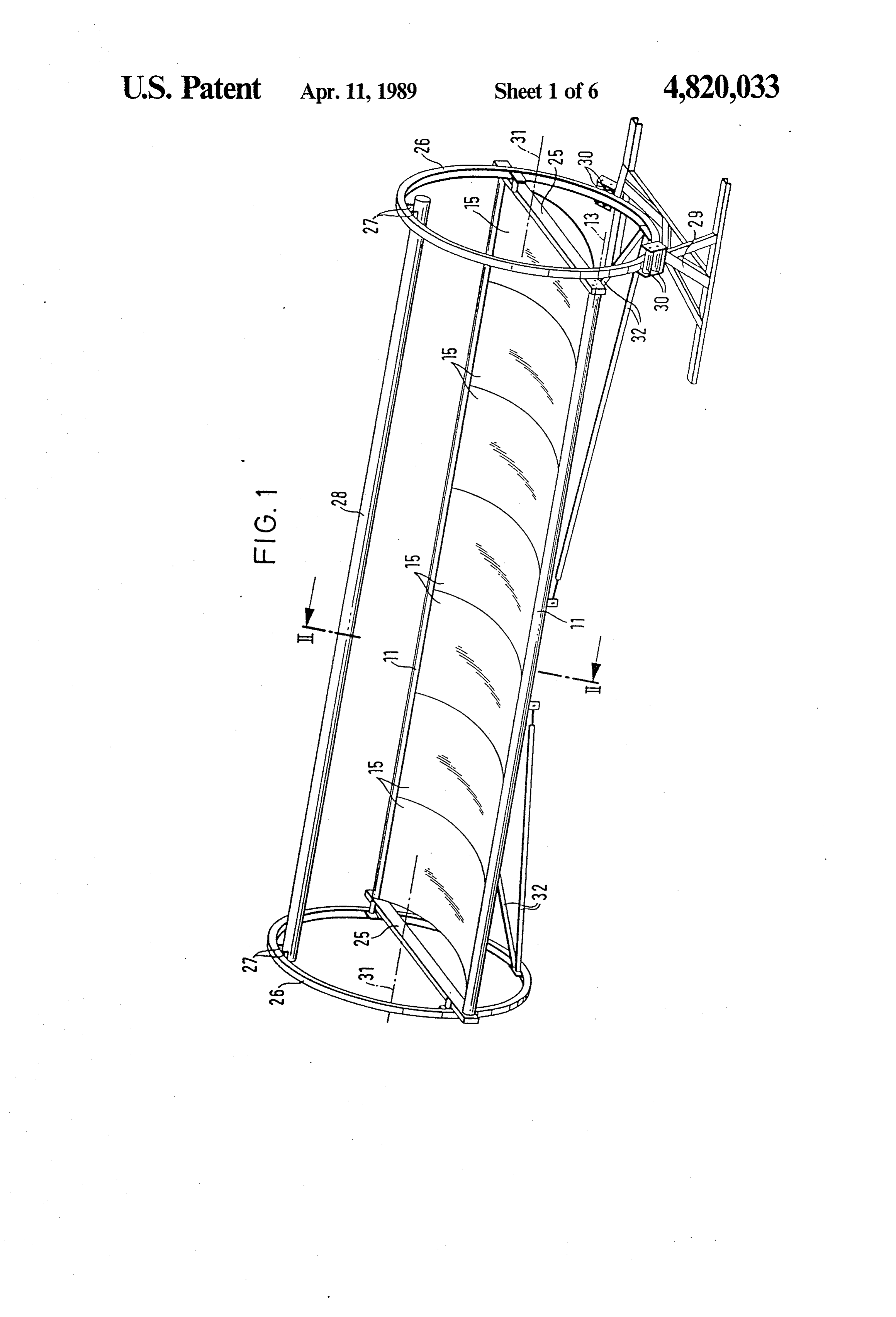
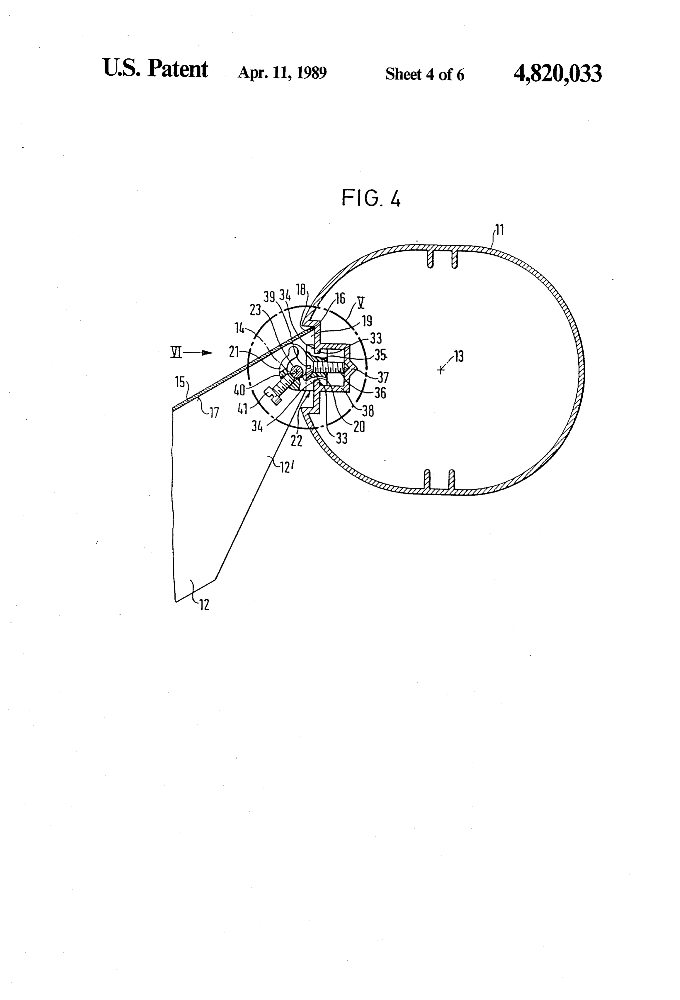
swivel axis into the release position or into the clamping effected (in a manner which is not illustrated) by means position as desired. of an electric motor via a transmission with a very high A further advantageous embodiment is characterized stepdown transmission ratio, or via a transmission in that the clamping section supports are secured at which acts on the periphery of the circular ring 26. their ends, diametrically, to stiff circular rings, option Horizontal connection beams or members 25 are ally via the connection members, with the axes of the mounted at the half heights of the circular rings 26, circular rings extending parallel to the parabolic axis extend diametrically across the circular rings 26, and and with their diameter substantially corresponding to carry elongate clamping section supports 11 at their the spacing of the two clamping section supports. With ends which project somewhat outwardly beyond the this arrangement is is particularly expedient for the 10 circular rings 26. The clamping section supports extend circular rings to be mounted on rollers and for them to from the connection member 25 of one circular ring 26 be rotatable in controlled manner about their common to the connection member 25 of the second circular ring axis. The stiff circular rings are thus simultaneously 26 which is arranged spaced at a considerable axial used to hold the solar mirror arrangement and also for distance from the first circular ring 26. Thin and resil the controlled rotation thereof. The controlled rotation 15 iently flexible sheet metal mirrors 15 which are of a ensures that the solar radiation falls at each point in time parabolically curved shape are arranged between the in the ideal direction exactly from the front onto the two clamping section supports 11 which extend parallel solar mirror arrangement so that the solar energy is to one another in a manner which will now be described extensively concentrated onto the radiation receiver in more detail in the following. Between the two circu which is located at the focal line. The latter is expedi 20 lar rings 26, which are illustrated in FIG. 1, there are ently secured to the circular rings opposite to the mirror located, in direct contact with one another and with the plates. connection members 25 a total of seven sheet metal The precise cutting of the parabolic edges of the mirrors 15. These mirrors have a rectangular shape in parabolic webs does not throw up any technical prob the non-curved state, with the longer side of the rectan lems, it is straight-forwardly possible, in accordance 25 gle extending in the direction which will later form the with a specially preferred embodiment of the invention, circumference.
for the parabolic edge of the parabolic webs to be of Stiffening struts 32 extend from the lower regions of precise parabolic shape, which can for example be the circular rings 26 to the central regions of the two achieved by stamping the parabolic webs out of sheet clamping section supports 11 in order to provide an metal using an appropriately shaped stamping tool. The 30 overall arrangement which is as stiff as possible against invention thus makes it possible to realize parabolic bending and twisting.
mirrors which concentrate the sunlight onto the radia As seen in FIGS. 2 to 4 parabolic webs 12 are ar tion receiver in a particularly precise manner. ranged behind the sheet metal mirrors 15 and each have The invention will now be described in the following a parabolic edge 17 which faces the sheet metal mirrors by way of example and with reference to the drawings 35 15. The parabolic webs 12 and their parabolic edges 17 in which are shown: extend in the circumferential direction of the sheet FIG. 1 a schematic perspective overall view of a metal mirrors 15.
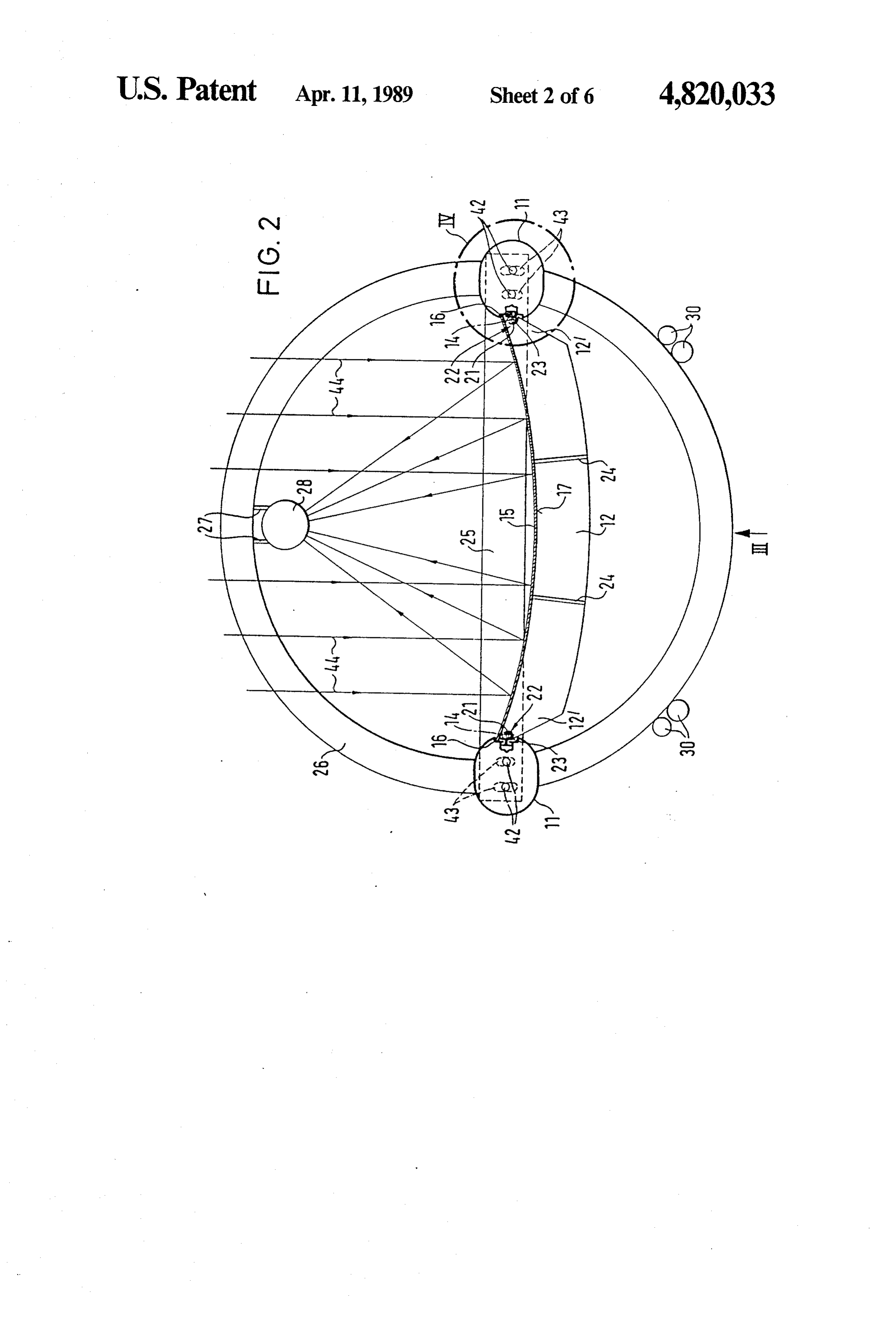
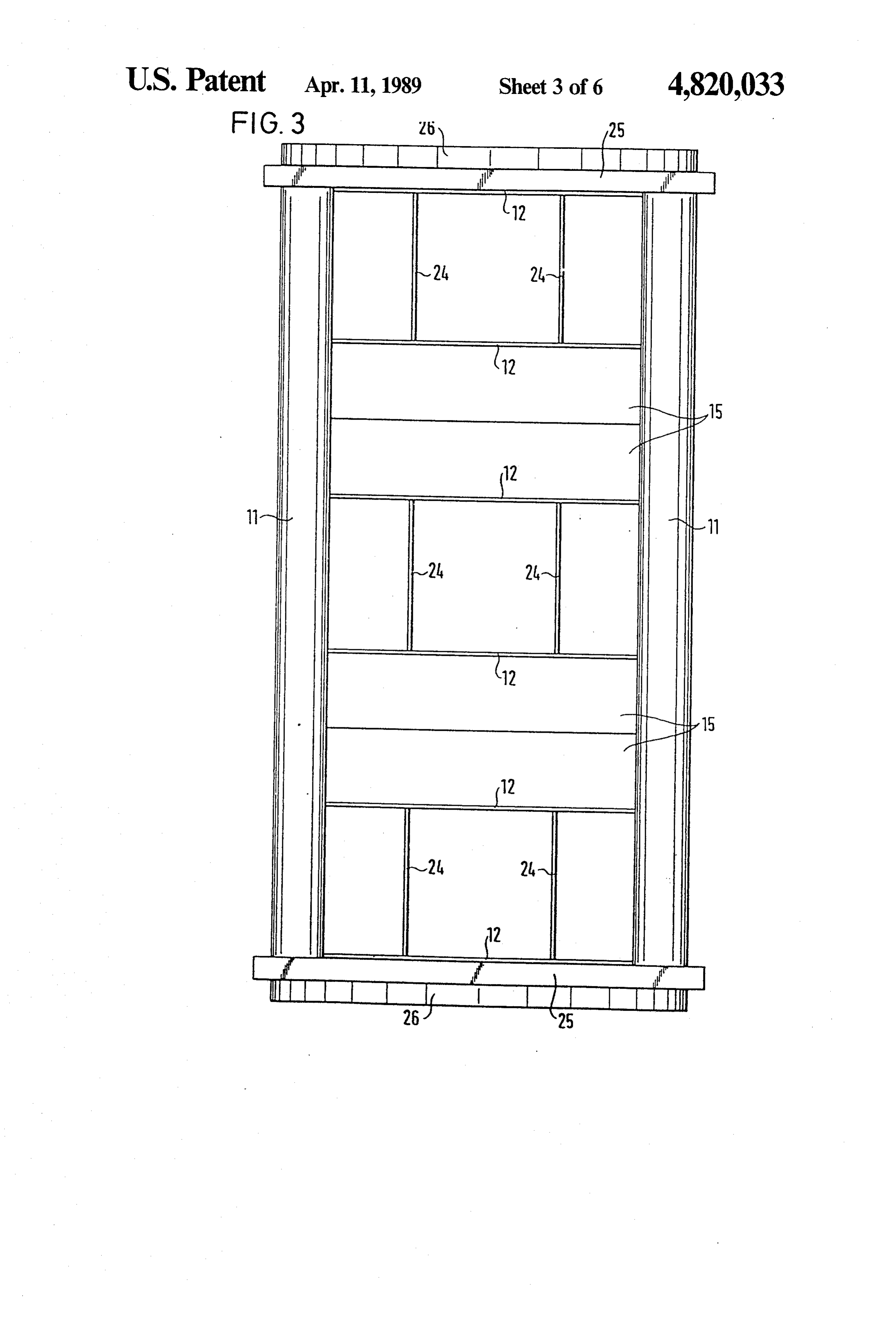
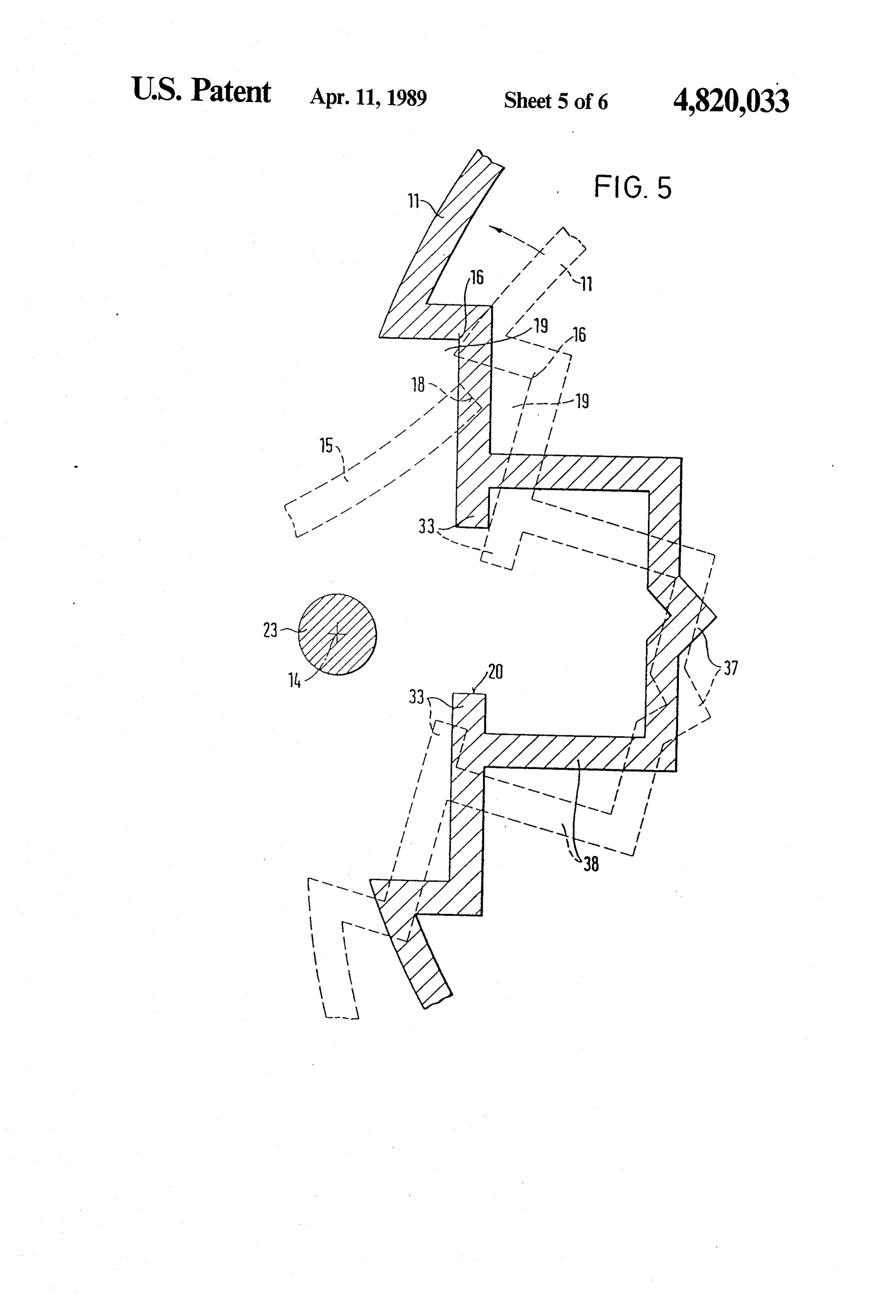
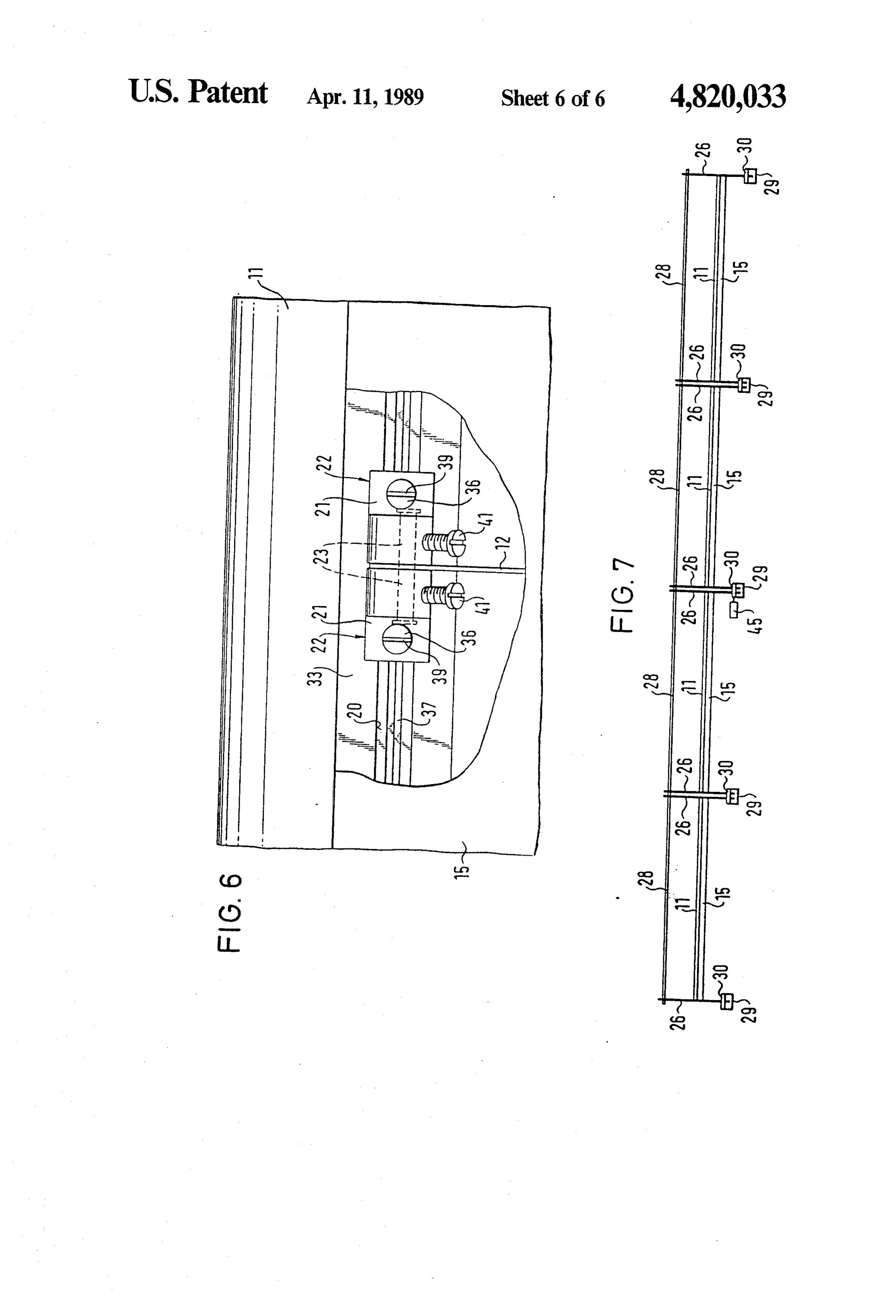
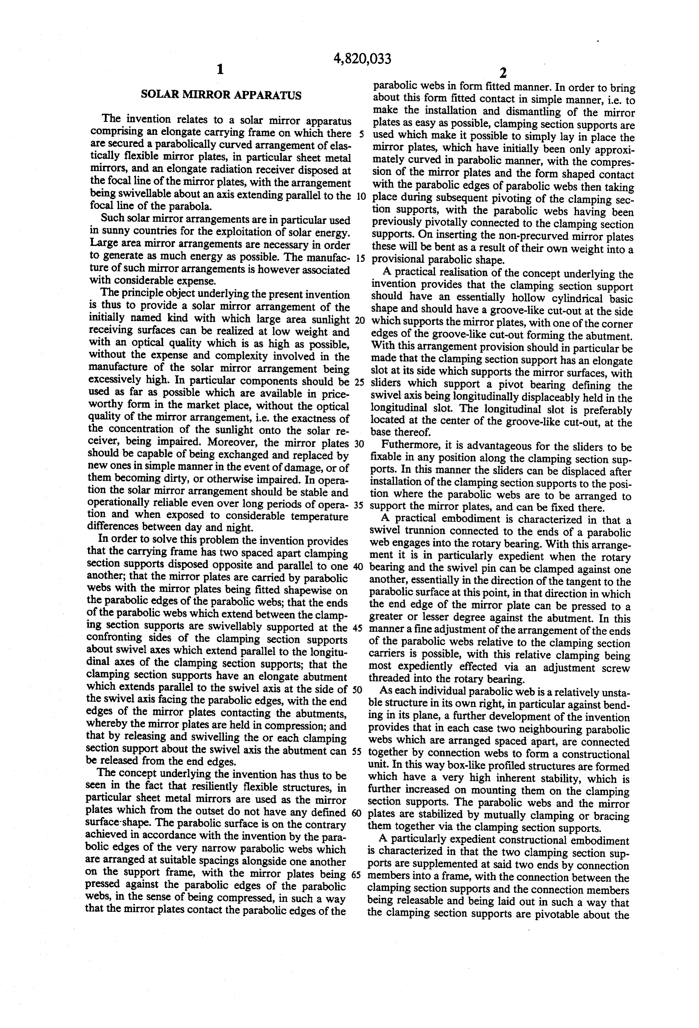
solar mirror apparatus in accordance with the inven In FIG. 3, in contrast to FIG. 1, only three sheet tion, metal mirrors 15 are shown alongside one another for FIG. 2 a schematic sectional view essentially on the the sake of simplicity. The same reference numerals are line II-II of FIG. 1, used to designate corresponding components in all em FIG. 3 a schematic view of a solar mirror apparatus bodiments.
in accordance with the invention in the direction of the As seen in FIG. 3 pairs of parabolic webs 12 which arrow III in FIG. 2, are arranged alongside and spaced apart from one an FIG. 4 the section IV from FIG. 2 to an enlarged 45 other are connected to one another and into a larger scale, constructional unit by connecting webs 24 which ex FIG. 5 the section V in FIG. 4 to illustrate the com tend in the longitudinal direction of the arrangement. ponents essential for the function of the device however As seen in FIG. 3 three such constructional units are to an enlarged scale, with the clamping section support provided spaced apart alongside one another. The flat being shown in broken lines in the released position and 50 surfaces of the parabolic webs 12 and of the connecting in full lines in the clamping position, webs 24 are perpendicular to the cylindrical paraboli FIG. 6 a view of the subject of FIG. 4 in the direction cally curved mirror surfaces 15.
of the arrow VI in FIG. 4, with the mirror plate 15 In accordance with FIGS. 2 and 4 a swivel pin or being partly broken away, and trunnion 23 extending parallel to the parabolic axis is FIG.7 a schematic side view of a solar mirror appara 55 arranged at the acute angled tapering ends 12" of each tus in accordance with the invention and consisting of parabolic web 12, right at the ends thereof. In accor several units placed together. dance with FIG. 6 the swivel pin 23 projects at both As seen in FIG. 1 base frames 29 are provided at the sides beyond each parabolic web and engages in swivel end faces of a solar mirror apparatus in accordance with mounts 21 provided on each side of each parabolic web. the invention, with only the base frame provided at the The swivel mounts are provided on sliders 22 which are right hand end face being shown in FIG. 1. These base displaceably arranged in the longitudinal direction in frames 29 are arranged on the ground. Plastic rollers 30 the clamping section carriers 11. For this purpose the with horizontal axes of rotation are rotatably secured, clamping section supports 11 have, in accordance with circumferentially spaced apart, on the base frames 29. A FIG. 4, a groove-like cut-out 19 in the base of which is circular ring 26 consisting of steel is mounted on the 65 formed a longitudinal slot 20. The ribs 33 which form rollers for rotation about its horizontally extending the marginal edges of this elongate slot 20 are engaged central axis 31, but is however constrained axially. The around by guide grooves 34 of the slider 22 to form a rotational drive of one of the circular rings 26 can be sliding seat in such away that the sliders 22 are securely
Page 10
held on all sides on the clamping section support 11, but In accordance with FIG. 2 the parallel sunlight 44 are however displaceable in the longitudinal direction. which is incident from the front onto the sheet metal The one half of this slider 22 has a threaded bore 35 into mirrors 25 is concentrated at the focal line of the sheet which a clamping screw 36 is threaded the end of which metal mirror 25 where the radiation receiver 28 is ar can be pressed against the base 37 of a clamping web 38 ranged.
provided on the clamping section support 11. The As seen in FIG. 4 the swivel axis 14 of each clamping screw has a screwdriver slot 39 in its head, by means of section support 11 extends parallel to its longitudinal which the screw can be actuated by a screwdriver, and axis 13.
clamped against the base 37 of the clamping web 38 The installation of the solar mirror arrangement in when the slider 22 is to be fixed at a specific position 10 accordance with the invention proceeds as follows: along the longitudinal extent of the clamping section After all components with the exception of the sheet support 11. metal mirrors 14 have been assembled together in the The swivel mount 21 is formed on each slider 22 manner which can be seen from FIG. 1 the clamping adjacent the threaded bore 35 and extends somewhat section supports 11 are loosened relative to the connec beyond the external periphery of the clamping section 15 tion members 25, by releasing the securing nuts in the support 11, in a direction towards the sheet metal mir region of the connection members 25, so that they can rors 15, and there engages around the swivel pin 23 be swivelled about the swivel axis 14 in accordance which is pushed through the parabolic webs 12. On the with FIG. 5 into the opened position illustrated in bro inner side of each swivel mount there is located a ken lines. This swivelling movement takes place in such threaded bore 40 which is directed approximately tan 20 away that the compressive abutment 16 is removed gential to the parabolic surface at this position through from the position to be adopted by the end eges 18 of which an adjustment bolt 41 is threaded the end of the sheet metal mirrors 15 after installation is complete. which is braced on the external periphery of the swivel The sheet metal mirrors 15 are now laid onto the pin. 23. The ideal situation would be a threaded bore parabolic edges 17 of the parabolic segments 12 so they which lies normal to the imaginary connection line of 5 adopt approximately the position which can be seen in the two opposite bores of a parabolic web so that no broken lines in FIG. 5 in which the end edges 15 still strains (forces) are subsequently introduced into the have a certain small spacing from the compressive abut parabolic web. The threaded bore should be executed ment 16 so that this insertion can be effected in a prob according to the geometrical shape of the clamping 30 lem free manner. As soon as all the sheet metal mirrors section. have been laid directly alongside one another onto the The arrangement of the parabolic webs 17 on the cylinder segments 12 which have previously been in swivel mount 21 of the slider 22 by means of the swivel stalled at suitable spacings the clamping section sup pins 23 is such that the tangent to the parabolic edge 17 ports 11 are swivelled in the direction of the broken line in the end region of each parabolic web 12 is directed 35 arrow of FIG. 5, so that the compression abutments 16 essentially into the upper corner edge of a groove-like come mirrorsinto contact with the end edges 18 of the sheet cut-out 19. In this way it is possible that the end corners metal 15. On further swivelling of the clamping 18 of the sheet metal mirrors 15, which are laid in solid lines in FIG.into section supports, the clamping position shown in 5, the sheet metal mirrors 15 are curved form on the parabolic edges 17 of the parabolic securely pressed in form fitted manner against the para webs 12, can lie within this corner edge which thus bolic edges 17 of the cylinder webs 12. In this manner forms a compressive abutment 16 for the end edges 18. the sheet metal
In accordance with the invention as seen in FIG. 6, own right and domirrors not have 15 which are flexible in their any defined shape precisely each parabolic web 12 is surrounded by two sliders 21 adopt the curved shape of the parabolic edges 17 of the of mirror symmetrical construction which clamp the cylinder segments 12 which expediently represents a parabolic web 12 between them and simultaneously fix 45 parabola. In the clamping position of the clamping sec its perpendicular position relative to the mirror surfaces tion supports 11 which are shown in solid lines in FIG.
5 and in the remaining Figures the clamping section
As seen in FIG. 2 the clamping section supports 11 supports are swivellably mounted at their end faces on the con nection members are fixed in the clamping position to the con nection members 25 so that they are swivellable about 50 tion point, so that25 abyprecisely tighting the nuts at the connec aligned and optically the swivel axis 14 of the swivel pins 23. For this purpose problemfree parabolic mirror arrangement is now pres securing spigots 42 which are only schematically illus ent.
trated can be provided at the end faces of the clamping Should a certain degree of malalignment be present section supports 11, with these securing spigots 42 en between gaging in elongate slots 43 in the connection members 55 support 11theinparabolic the webs 12 and the clamping section region of one or other slider 21 then 25 and with these elongate slots 43 being illustrated in this can be accurately removed without problem by broken lines and being curved around the swivel axis rotating the corresponding adjustment screw 41. 14. The securing spigots 42 can be constructed as bolts Dismantling takes place in the reverse sense. (not illustrated) and can be fixed in a specific swivel The installation of the parabolic webs 12 is corre position relative to the connection members 25. spondingly simple. The parabolic webs 12 which have By releasing the nuts which are not illustrated but are been assembled into larger constructional units in accor arranged on the bolts 42 the clamping section supports dance with FIG.3 are hung by means of the swivel pins 11 can be swivelled about the swivel axis 14.
An elongate radiation receiver 28 is arranged in ac wardly open and the overall arangements can up 23 into the swivel mount 21 which are preferably
cordance with FIG. 1 opposite to the connection mem 65 brought precisely into the correct position by lateral bers 25 and the sheet metal mirrors 15 and is secured via displacement of the sliders 21. The sliders 21 are then securing webs 27 to the two spaced apart stiff circular pressed from both sides against the associated parabolic rings 26. webs 12 and can be fixed in this position by screws 36.
Page 11
The fine adjustment can then take place by rotating the wherein said means for adjustably connecting permits adjustment screws 41. said clamping section supports to be pivoted about In accordance with FIG. 7 several solar mirror ar said support swivel axis into said release position or rangements in accordance with FIG. 1 can be arranged said mirror retaining position. behind one another and can be rotationally coupled 5 3. The solar mirror apparatus of claim 1, wherein together in a suitable manner. In this way a single motor each said support has a substantially hollow ellipsoidal 45 is sufficient for driving all the coupled solar mirror shape defining a groove-like cut-out having an edge at a arrangements. side supporting said mirror edge, and wherein said abut The, webs 12 could also deviate from the parabolic ment is formed from a corner edge of said groove-like shape and could for example be approximately circular 10 Cut-Out.
when only the predominant part of the solar radiation frame4. The solar mirror apparatus of claim 1, wherein said falls onto the radiation receiver 28. is controllably rotated about said longitudinal I claim: axis such that said mirror is directed towards the sun. 1. A solar mirror apparatus, comprising: 5. The solar mirror apparatus of claim 1, wherein said mirror includes a flexible sheet of metal covered with a an elongate carrying frame, having a longitudinal 15 reflective axis, adapted to be rotated about said longitudinal foil.
axis; 6. The solar mirror apparatus of claim 1, wherein said first and second clamping section supports, spaced pivotal connecting means are sliders which are longitu apart and disposed parallel to said longitudinal axis, 20 dinally 7. The displaceably held in said elongate slot.
solar mirror apparatus of claim 6, wherein said each said support including an elongate abutment, sliders may be fixed in any position along said clamping parallel to and facing said longitudinal axis, section supports.
adapted to exert a compressive force, and further 8. The solar mirror apparatus of claim 6, wherein said including an elongate slot, parallel to said longitu web includes a plurality of spaced apart webs and a dinal axis; 25 connection web for joining said spaced apart webs into means for adjustably connecting said supports to said a single web unit.
frame such that each said support can swivel about 9. The solar mirror apparatus of claim 1, wherein said a support swivel axis parallel to said longitudinal frame further includes first and second stiff circular aX1S, rings having a diameter substantially the same as the a parabolic web including first and second parallel 30 distance separating said clamping section supports, an sides, each said side including a swivel pin defining imaginary axis connecting a center of each ring being a web swivel axis parallel to said longitudinal axis; parallel to said longitudinal axis, said rings being se first and second pivotal connecting means for pivot cured to the ends of said clamping section supports by ally connecting said web to said supports, each said said means for adjustably connecting. pivotal connecting means adapted to slidadably 35 attach to a said support and rotably engage a said said10.receiver
The solar mirror apparatus of claim 9, wherein is secured to said rings such that said re swivel pin, thereby pivotally connecting said web ceiver faces said mirror.
to said supports; 11. A solar mirror apparatus, comprising: an elastically flexible sheet metal mirror having first an elongate carrying frame, having a longitudinal and second parallel sides, adapted to be releasably axis, adapted to be rotated about said longitudinal held against and conformed to the shape of said axis;
parabolic web, said mirror sides contacting said first and second clamping section supports, spaced abutments and being forced by the compressive apart and disposed parallel to said longitudinal axis, force exerted by said abutments to conform to the each said support including an elongate abutment, parabolic shape of said web, an upper surface of 45 parallel to and facing said longitudinal axis, said mirror defining a parabolic mirror having a adapted to exert a compressive force, and further focal line parallel to said longitudinal axis when so including an elongate slot, parallel to side longitu shaped; and dinal axis;
an elongate radiation receiver, held by said frame and first and second slider means, adapted to slidably disposed at said focal line, for receiving solar radia 50 engage in a said slot and be longitudinally displace tion reflected by said mirror; ably held therein, each said slider means including said means for adjustably connecting allowing the a pivot bearing;
supports to be swiveled to a release position means for adjustably connecting said supports to said permitting said mirror to be placed on or re frame such that each said support can swivel about moved from said web, whereupon said means for 55 a support swivel axis parallel to said longitudinal adjustably connecting is tightened placing said axils;
supports in a mirror retaining position, a parabolic web including first and second parallel said pivotal connecting means controlling the sides, each said side including a swivel pin adapted contact between said mirror sides and said abut to engage a said pivot bearing in said slider means, ments, and controlling thereby the compressive said swivel pin and pivot bearing defining a web force exerted by said abutments to force said swivel axis parallel to said longitudinal axis; mirror to assume the parabolic shape of said web; an elastically flexible sheet metal mirror having first said frame being rotated to cause said mirror to and second parallel sides, adapted to be releasably face the sun. held against and conformed to the shape of said 2. The solar mirror apparatus of claim 1, wherein said 65 parabolic web, said mirror sides contacting said frame further includes first and second connection abutments and being forced by the compressive members, each said connection member connecting an force exerted by said abutments to conform to the end of said clamping section supports to said frame, and parabolic shape of said web, an upper surface of
Page 12
said mirror defining a parabolic mirror having a ments, and controlling thereby the compressive focal line parallel to said longitudinal axis when so force exerted by said abutments to force said shaped; and mirror to assume the parabolic shape of said web; an elongate radiation receiver, held by said frame and said frame being rotated to cause said mirror to disposed at said focal line, for receiving solar radia- 5 face the sun.
tion reflected by said mirror; 12. The solar mirror apparatus of claim 11, wherein said means for adjustably connecting allowing the said pivot bearings and said swivel pins are adapted to supports to be swiveled to a release position be clamped against one another substantially in the permitting said mirror to be placed on or re- direction of a tangent to the parabolic shaped upper moved from said web, whereupon said means for 10 surface of said mirror, at a location of said pivot bear adjustably connecting is tightened placing said ings and swivel pins, said clamping being in a direction supports in a mirror retaining position, in which said mirror sides compressively contact said said pivotal connecting means controlling the con- abutments.
tract between said mirror sides and said abut- k . . . .
Provenance
- Collection
- Cited prior art
- Original PDF
- patentimages.storage.googleapis.com →
- Filed
- 1987-12-23
- Pages
- 12
- Method
- pdftotext (the PDF's own text layer) + pdftoppm 300dpi page scans
- Source
- Google Patents bibliographic record
- Granted
- 1989-04-11
- Inventors
- Erwin Sick; Erwin Sick GmbH Optik Elektronik
- Transcribed from
- patentimages.storage.googleapis.com →