patent · US4515148
Cylindro-parabolical solar energy collector
7 May 1985
Page 1 — bibliographic record
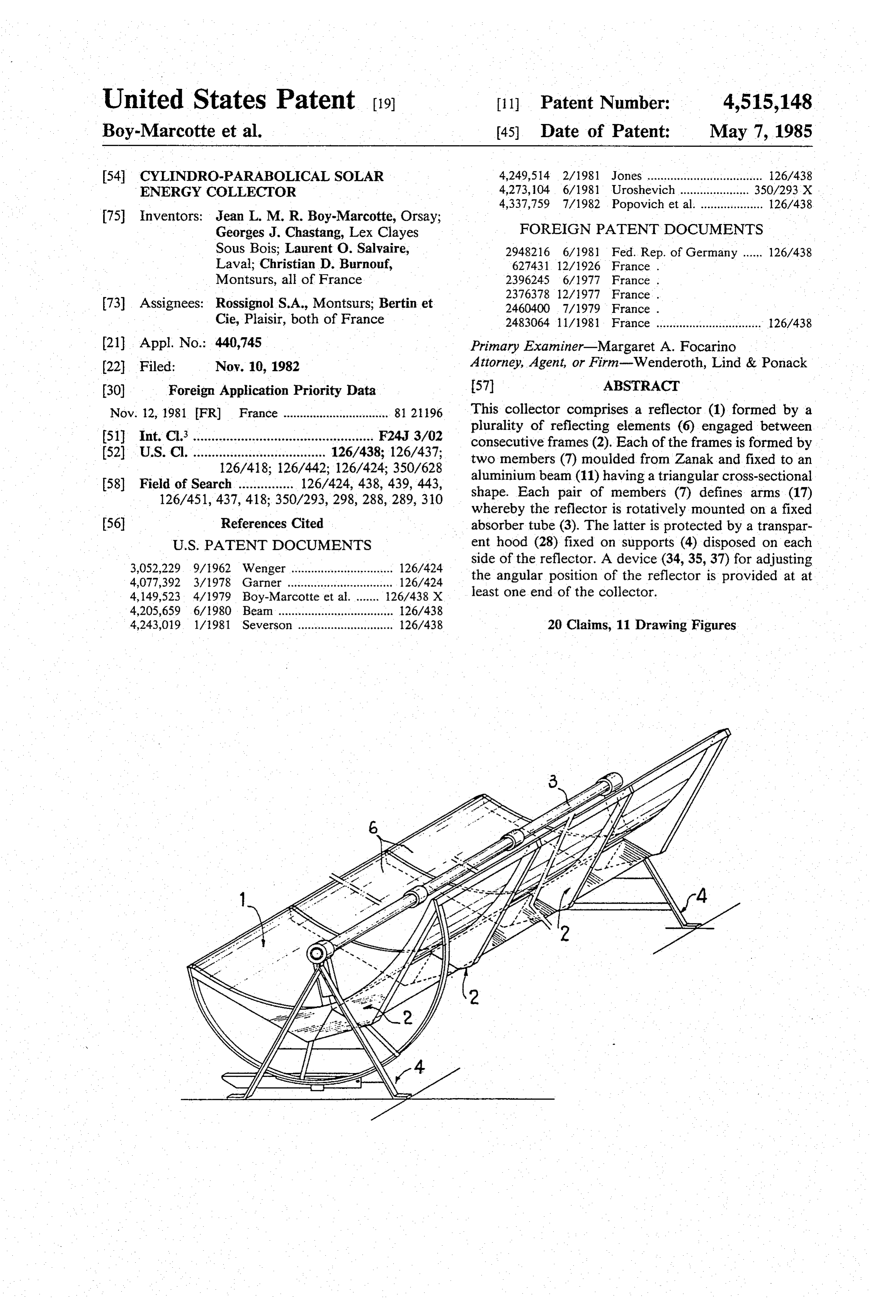
United States Patent (19) 11 Patent Number: 4,515,148 Boy-Marcotte et al. (45) Date of Patent: May 7, 1985 54 CYLINDRO-PARABOLICAL SOLAR 4,249,514 2/1981 Jones ................................... 26/438 ENERGY COLLECTOR 4,273, 104 6/1981 Uroshevich .......... ... 350/293X
75 Inventors: Jean L. M. R. Boy-Marcotte, Orsay;
Georges J. Chastang, Lex Clayes FOREIGN PATENT DOCUMENTS
Sous Bois; Laurent O. Salvaire, 2948216 6/1981 Fed. Rep. of Germany ...... 126/438 Laval; Christian D. Burnouf, 627431, 12/1926 France .
Montsurs, all of France 2396245 6/1977 France .
73) Assignees: Rossignol S.A., Montsurs; Bertin et 2460400 7/1979 France . Cie, Plaisir, both of France 2483064. 11/1981 France ................................ 26/438 21 Appl. No.: 440,745 Primary Examiner-Margaret A. Focarino (22 Filed: Nov. 10, 1982 Attorney, Agent, or Firm-Wenderoth, Lind & Ponack 30 Foreign Application Priority Data 57 ABSTRACT Nov. 12, 1981 FR) France ................................ 81 296 This collector comprises a reflector (1) formed by a plurality of reflecting elements (6) engaged between 51 Int. Cl. ................................................. F24, 3/02 consecutive frames (2). Each of the frames is formed by (52) U.S. Cl. .................................... 126/438: 126/437; two members (7) moulded from Zanak and fixed to an 126/418; 126/442; 126/424; 350/628 aluminium beam (11) having a triangular cross-sectional 58) Field of Search ............... 126/424, 438, 439, 443, shape. Each pair of members (7) defines arms (17) 126/451, 437, 418; 350/293, 298, 288, 289, 310 whereby the reflector is rotatively mounted on a fixed 56 References Cited absorber tube (3). The latter is protected by a transpar
3,052,229 9/1962 Wenger ............................... 126/424 side of the reflector. A device (34,35, 37) for adjusting 4,077,392 3/1978 Garner ................................ 126/424 the angular position of the reflector is provided at at 4,149,523 4/1979 Boy-Marcotte et al........ 26/438 X least one end of the collector.
4,205,659 6/1980 Beam ................................... 126/438 4,243,019 1/1981 Severson ............................. 126/438 20 Claims, 11 Drawing Figures
Page 2
Drawing sheet — no readable text.
Page 3
Drawing sheet — no readable text.
Page 4
Drawing sheet — no readable text.
Page 5
Drawing sheet — no readable text.
Page 6
Drawing sheet — no readable text.
Page 7
FIG. 9 is a partial view, to an enlarged scale relative
CYLINDRO-PARABOLICAL SOLAR ENERGY to FIG. 7, of the means for putting the protective film
FIG. 10 is a partial elevational and sectional view of
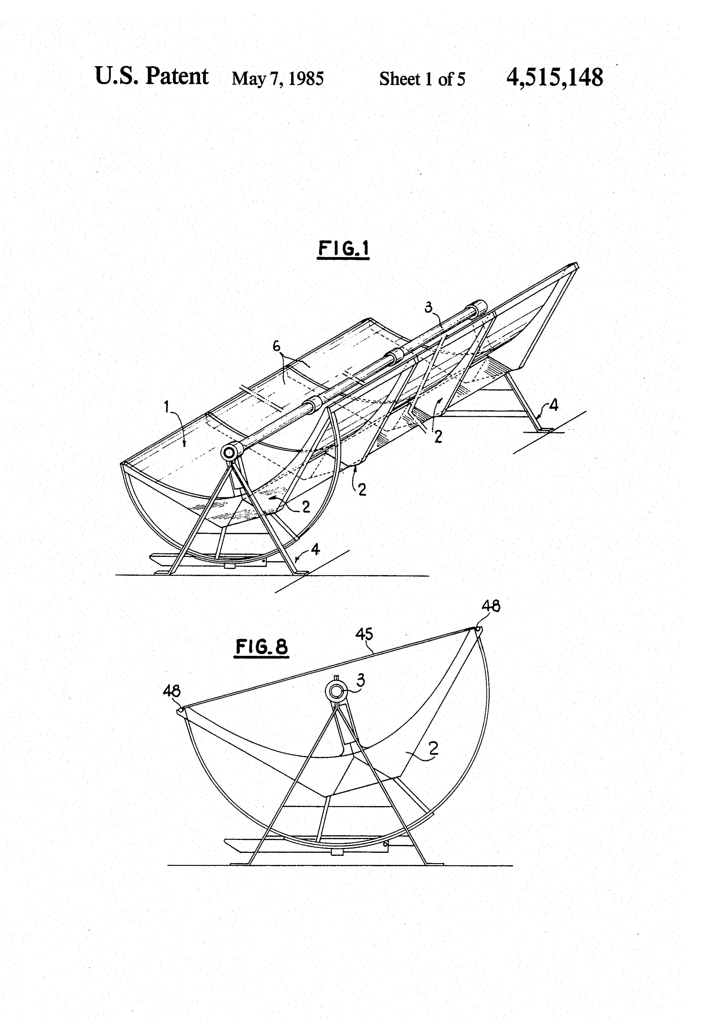
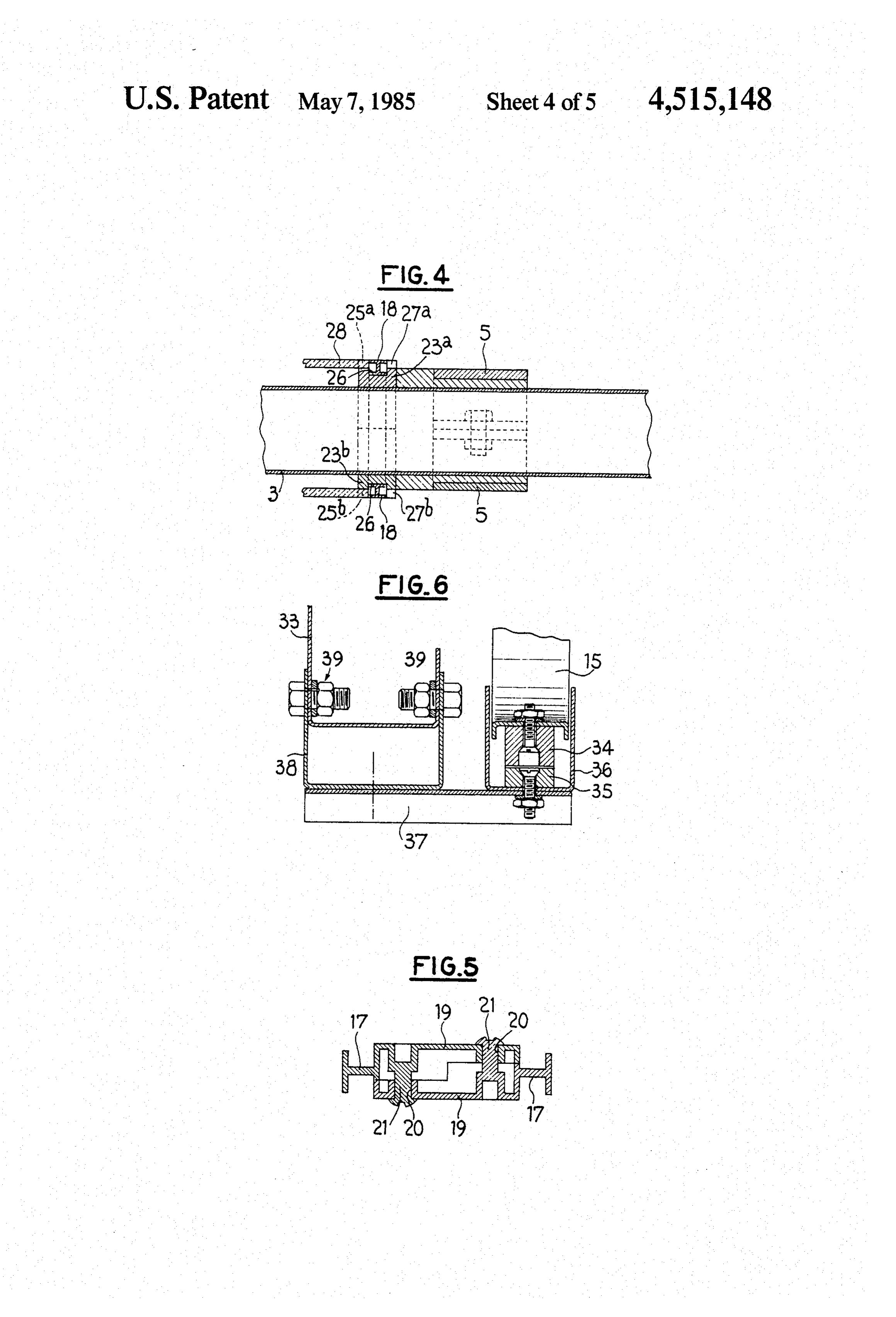
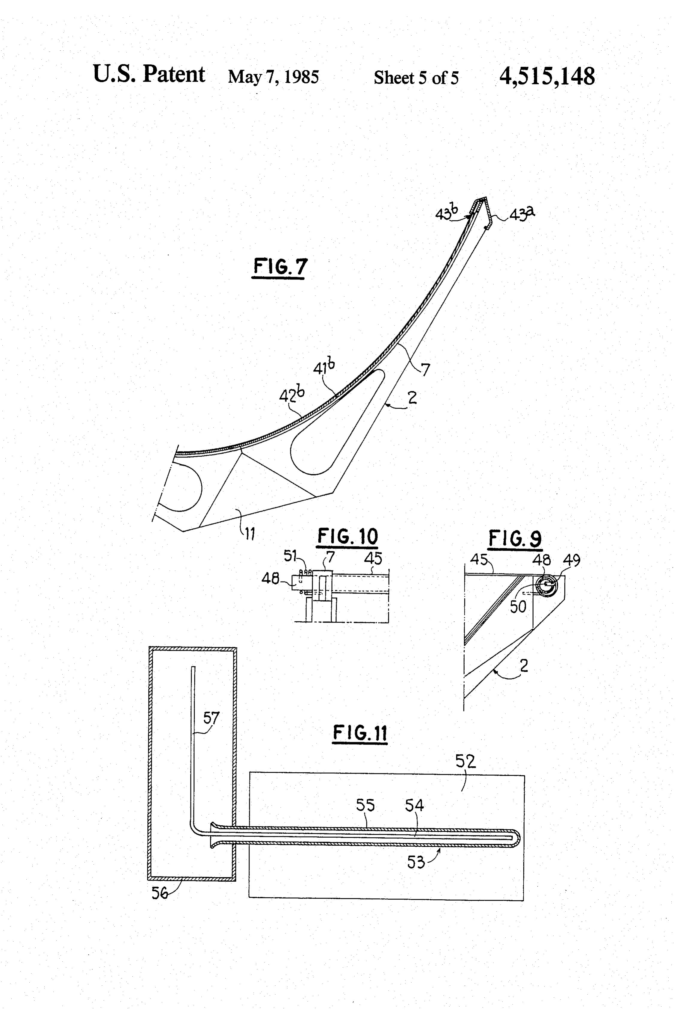
The present invention relates to solar energy collec- 5 the tensioning means for the protective film of the col tors having a concave mirror and more particularly lector of FIG. 8, and relates to collectors of the cylindro-parabolical type. FIG. 11 is a diagrammatic view of an embodiment of Collectors of this type are known which comprise a the connection of the collector according to the inven reflector of cylindro-parabolical shape and an absorber tion with a storage tank employing coaxial pipes. tube having an axis coincident with the focal line of the 10 The solar energy collector shown in FIG. 1 com reflector and in which a heat transfer fluid circulates. prises a trough-like cylindro-parabolical reflector 1 According to some known embodiments, the reflec carried by frames 2 evenly spaced apart longitudinally tor is formed by sheets of reflecting material stiffened of the reflector. A radiation absorbing tube 3, in which by frames. is adapted to circulate a heat transfer fluid, is disposed in A collector of the cylindro-parabolical type must be 15 such a manner that its axis coincides with the focal line orientable in accordance with the direction of the sun. of the reflector 1. At both ends, the tube 3 is mounted on In certain cases, the collector formed by the reflector fixed supports 4 the upper ends of which form collars 5. and the absorber tube is mounted to be rotatable about The collectors is rotatively mounted relative to the the top of the reflector, which presents the drawback of absorber tube 3 between the supports 4 in a manner requiring flexible connections between the absorber 20 which will be described in detail with reference to FIG. tube and the rest of the unit. 2.
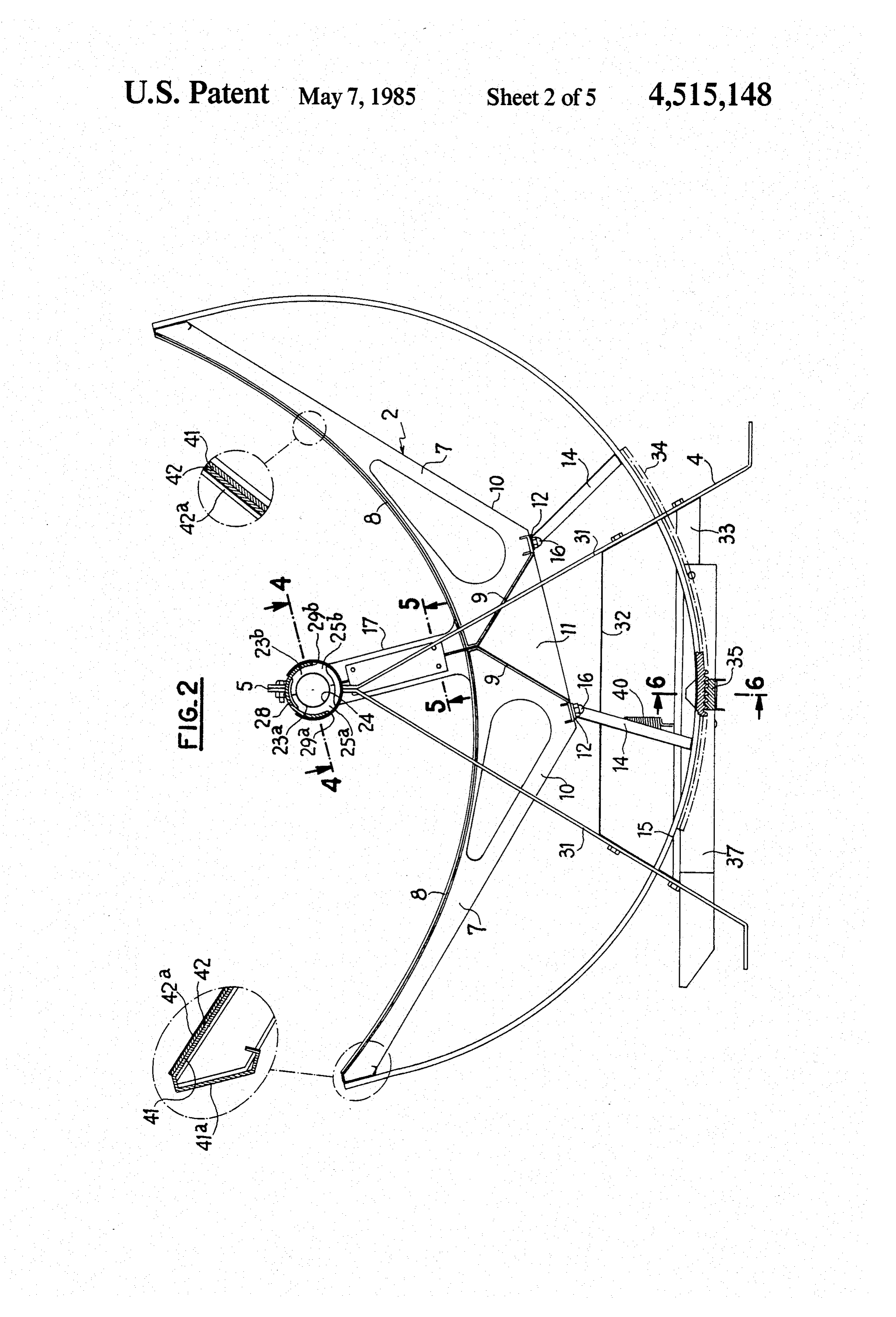
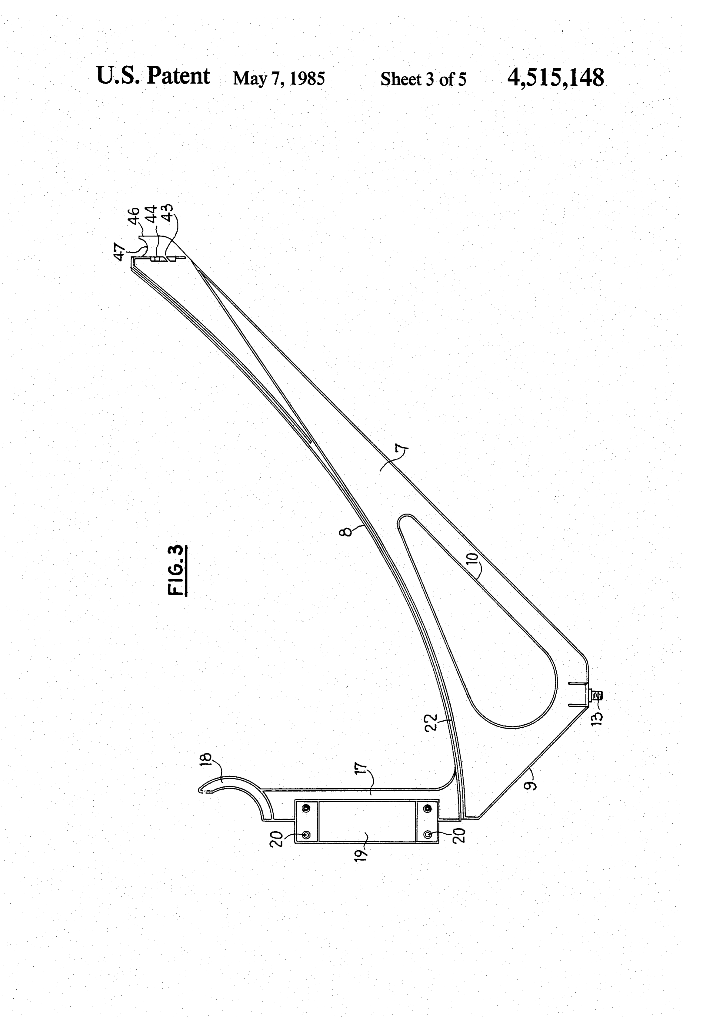
In other cases, the absorber tube is fixed and the The reflecting surface of the reflector 1 is formed by reflector is mounted to be rotatable about the absorber juxtaposed elements 6 assembled by the frames 2. tube. Each of these frames is formed by two identical mem This second arrangement enables the flexible connec 25 bers 7 moulded for example from Zamak. Each member tions between the absorber tube and the heat transfer has a concave side 8 in the shape of a semi-parabola and fluid circuit to be eliminated. two sides 9 and 10 disposed at a right angle. These Further, the movable part of the unit is lighter. members 7 adapted to form the parabolical framework An object of the invention is to provide a solar en for the reflecting surface bear in pairs as shown in FIG. ergy collector which combines relative lightness with 30 2 on a beam 11 of triangular cross-section, preferably great simplicity of assembly. made from aluminium. The beam 11 has lateral flanges Another object of the invention is also to provide a 12 in which are formed apertures through which extend solar energy collector which may be mass-produced. studs 13 provided at the apex of the L-shaped structure The invention therefore provides a solar energy col formed by the sides 9 and 11 of each member 7. The lector comprising a concave reflector, a heat absorber 35 studs 13 also serve to fix struts 14 adapted to support a tube disposed along the focal axis of the reflector, a heat hoop member 15 whose ends are secured to the ends of transfer fluid circulating in said tube, said reflector the members 7 opposed to the beam 11. Tightening nuts being rotatably mounted about said heat absorber tube 16 cooperate with the studs 13.
and being detachably mounted on said tube through With reference now to FIG. 3, it can be seen that pivot means surrounding said tube, said pivot means each of the members 7 further comprises, moulded including at least one relatively movable locking ele therewith, an arm portion 17 whose free end is con ment whose relative motion opens a radial passage for structed in the form of a portion of a circular ring 18 releasing the tube, thereby allowing the tube to remain adapted to support the absorber tube 3 in a manner in position without interruption of the flow of the heat which will be described in detail with reference to FIG. transfer fluid. 45 4.
Further features of the invention will be apparent As shown in FIG. 5, each arm portion 17 has a rec from the ensuing description with reference to the ac tangular-shaped projecting portion 19 which is companying drawings which are given solely by way of moulded therewith and inwardly overhangs. Formed in example and in which: each projecting portion 19 are orifices 20 for receiving FIG. 1 is a diagrammatic perspective view of a solar 50 pins 21 provided in the arm portion 17 of the comple energy collector according to the invention; mentary member 7, the hammering-over of which pins FIG. 2 is a side elevational view to an enlarged scale ensures the assembly of said arm portions with respect of the collector of FIG. 1; to each other so as to form an arm connected to the tube FIG. 3 is a view to an even greater scale of a frame 3.
element which is part of the construction of the collec- 55 On each side of its semi-parabolical sides, each mem tor according to the invention; ber has a semi-parabolical groove 22 for receiving the FIG. 4 is a partial sectional view taken on line 4-4 of edge portion of an element 6 of the reflector 1. FIG. 2; The absorber tube 3 is mounted in the open rings or FIG. 5 is a sectional view taken on line 5-5 of FIG. forks constituted by the ends 18 of the arm portions 17 2; 60 of the semi-parabolical members 7 assembled with each FIG. 6 is a partial sectional view taken on line 6-6 of other, by means of a ring 23 comprising two semi-rings FIG. 2; 23a, 23b engaged in the fork formed by the ends 18 of FIG. 7 is a partial sectional diagrammatic view of a the arm portions 17, by rotation. The semi-rings 23a, modification of the reflecting material employed in the 23b are made from an insulating material such as for collector and of the manner in which it is assembled; 65 example Teflon. They define a passage 24 of circular FIG. 8 is a diagrammatic side elevational view of the cross-sectional shape the inside diameter of which is solar energy collector according to the invention which equal to the absorber tube 3. The outside diameter of the is protected by a film of plastics material; ring thus formed is equal to the inside diameter of the
Page 8
part-circular shape of the inside of the fork formed by by an aluminized plastics material adhered to the sheet the ends or branches 18 of the arm portions 17. The 42 forming a substrate. The support sheet 41 may be rings, 23a, 23b have on their two end faces radially made in two parts of length corresponding to the outwardly extending projections 25a, 25b which define curved sides 8 of each of the members 7 which consti therebetween a passage 26 whose width is equal to that 5 tute each frame, while the sheet 42 forming a substrate of the ends 18 of the arm portions 17. The projections for the reflecting film 42 constitutes a single element 25a and 25b extend in a portion of the periphery of the inserted between two consecutive frames. The sheet 41 respective semi-rings 23a, 23b which subtends an angle is folded at its ends over against the corresponding end. at the centre of the ring 23 which is slightly less than the of the member 7 and then inserted in a slot 43 formed in angle subtended by the opening or entrance of the fork 10 this member FIG. 3. As shown by the inset surrounded 18, 18 at the centre of the fork corresponding to the by a dot-dash circle shown at the left part of FIG. 2, the centre of the ring 23 and the axis of the tube 3, so as to sheet 41 is thereafter immobilised by a screw engaged in permit the engagement of the semi-rings in said fork screwthreaded holes 44 formed in the end of the mem. through the opening or entrance of the latter. By there ber 7. The folded portions 41a of the sheet 41 thus form. after successively turning each semi-ring 23a, 23b about 15 struts for stiffening and maintaining the frames. .. . . the absorber tube 3 so that its respective projections In order to ensure that the reflecting film 42a retains 25a, 25b trap the curved ends or branches 18 of the arm a perfect condition in the vicinity of the parabolical portions 17, the reflector is locked on the absorber tube groove 22, the film 42a is slightly narrower than the 3. The unlocking may be achieved just as easily by substrate 42 so that the lateral edge portions of the latter carrying out operations which are the opposite of those 20 are devoid of reflecting film and are alone engaged with just described, so that the reflector is removable. the sheet 41 in the parabolical groove 22, which avoids The semi-rings 23a, 23b further comprise in the pro the formation of local creasing and tearing of this film jections 25a, 25b, portions 27a, 27b of smaller diameter upon assembly.
which together define a bearing portion on which bears FIG. 7 shows a modification of the reflecting surface . . . the end of a protective hood 28 of transparent material 25 which may be employed for forming the reflector of the which caps the absorber tube 3. The hood 28 is of tubu collector according to the invention. . . . . . . . lar shape and is open in the part thereof facing the re According to this modification, the elements of the flector 8. The edges of the opening of the hood 28 bear reflecting surface comprise a support element formed against radial stops 29a, 29b constituted in the projec by a sheet 41b of stainless steel engaged in the grooves tions 25a, 25b by the hollowing-out of portions of bear 30 of two consecutive frames 2 and on which is adhered a ing surfaces 27a, 27b for the hood 28. film of reflecting material 42b, composed of aluminized The supports 4 of the collector are fixed to the ab plastics material. . .. . . . . . .. .. sorber tube 3 by collars 5, by the clamping of said tube The sheets 41b terminate in sharp edges and joint with interposition of a shouldered sleeve 30 of insulat covers 43a are mounted at the free ends of the members ing material, such as Teflon. Each support 4 has the 35 7 which constitute the frames 2. The joint covers, general shape of an A. at the apex of which is provided which perform the function of reinforcing beams for the . . . . the collar 5 which is defined by the upper ends of the reflector and spacer members, are formed by section . legs 31 of the A. It comprises a first cross-member 32. members having an oblique passage 43b in which the The cross-member of one of the supports is adapted lateral edge portion of the reflecting surface 41b, 42b is to receive means for controlling the device adjusting 40 engaged.
the angular position of the reflector in accordance with The joint covers 43a thus also perform the function of the orientation of the sun. longitudinal support means for the sheets 41b which This adjusting device comprises a rack 34 fixed on a prevent them from bending between two frames, and . . . portion of the hoop member 15 provided at at least one the function of protection means against humidity for end of the collector. Cooperative with the rack 34 is a 45 the junction between the sheet 41b and the film.42b. toothed member 35 which is fixed by means of a U FIG. 8 shows an embodiment of the solar energy. shaped guiding and protecting member 36 on an actuat collector according to the invention in which the reflec ing lever 37. The lever 37 is pivoted to the cross-mem tor and the absorber tube are protected by a transparent ber 32 by a member 38 in the shape of a fork which film 45 held taut on the frame that the assembly of the . . . surrounds the flanges of the cross-member 32 and which 50 frames 2 and the flanges of the supporting sheets 41 of is secured to these flanges by bolt-and-nut assemblies 39. the reflector constitute. In order to mount this film 45, The actuating lever 37 is maintained in an upper posi the free ends of the members 7 which constitute the tion against the cross-member 32 by a return spring 40 frames are each provided with an outer projection 46 in whose ends are fixed, on one hand, to the lever 37, and, which is formed a groove 47 for receiving a rod 48 on the other hand, to the upper part of the cross-mem 55 which constitutes the tensioning member of the film 4 ber. Thus, the film 45 may easily be mounted and disassem bled either for replacing or for gaining access to the
If it is desired to render the adjustment of the orienta tion of the reflector automatic, the toothed member 35reflector or the absorber tube.
may be replaced by a worm which would engage the The means for mounting the film 45 are shown in rack 34 and would be driven an electric motor con 60 more detail in FIGS.9 and 10. As shown in FIG.9, each trolled by means responsive to the orientation of the rod 48 comprises a longitudinal slot 49 in which the S. edge portion of the film 45 is passed, this edgeportion The reflecting surface of the reflector is formed, as having a beading 50 whose thickness exceeds the width shown in the inset surrounded by the dot-dash line of of the slot 49, this beading being formed by the welding FIG. 2 shown in the right part of this Figure, by the 65 together of a plurality of thicknesses of film. The latter::...' superimposition of a support sheet 41 made of metal or is wound at least once round the rod 48. - ... ;- plastics and a metal sheet 42 forming a substrate for a At least one of the rods 48 is provided, as shown in . film of reflecting material 42a constituted, for example, FIG. 10, with tensioning means 51 which may be
Page 9
formed a coil spring which is under torsional stress and ring means having an inside diameter for receiving said is mounted at one end of the rod 48, one end of the tube and an outside shape which is such as to enable the spring being engaged in an orifice provided in the rod ring means to be engaged inside said opening of the while the other end is rigid with the corresponding respective fork in a first rotational position of the ring member 7. The mounting is achieved by putting the means relative to the fork and to lock the ring means in spring under a given stress and it will be understood the fork after rotation of the ring means about said axis that any variation in the length of the film 45 due to its expansion or contraction is compensated for by the to a locking position, said ring means being releable rotation of the rod 48 under the action of the spring 51. lockingtheposition from fork by rotation of the ring means from said to said first rotational position thereof.
The solar energy collector just described has, relative O 2. A collector according to claim 1, wherein said end to similar devices of the prior art, the advantage of portion of each arm defines a partly annular fork partly being extremely easy to assemble owing to the simplic surrounding the absorber tube, said opening is part-cir ity of the component parts. cular, said entrances has a width less than the diameter The fact that the frames 2 are made from moulded of said part-circular opening, and said ring means has an members assembled with a central stiffening and sup 15 outside diameter such as to enable the ring means to fit porting beam, ensures a good reproducibility of manu in said part-circular facture, which is very important in production on an opening.
industrial scale. 3. A collector according to claim 1, wherein the re The fact that the reflector can be easily removed ments flecting surface of the reflector comprises sheet ele from the absorber tube permits a rapid replacement of 20 rial, covered with a film of aluminized plastics mate defective parts. and having edge portions engaged in confronting In the embodiment just described, the absorber tube is grooves of two consecutive frames, ends of said ele ments being engaged in passageways provided in joint formed by a single tube in which the heat transfer fluid covers which form reinforcing struts for longitudinal circulates. However, it is possible to arrange the ab edge portions of the reflector and are fixed to free ends sorber tube in the form of two concentric tubes, the 25 central tube serving to circulate the hot water, while the of said members forming said frames. peripheral tube defines with the outer surface of the 4. A solar energy collector comprising a concave central tube a passageway in which the cold water cylindro-parabolical reflector having an axis through circulate. the focus of the reflector, a heat absorber tube disposed Such an arrangement is shown in FIG. 11. In the 30 along and coincident with said axis, a heat transfer fluid latter, the collector 5 according to the invention, shown circulating in said tube, pivot means pivotably and de diagrammatically at 52, comprises an absorber tube 53 tachably mounting said reflector on said heat absorber formed by an inner tube 54 and an outer tube 55 coaxial tube, said pivot means comprising frames carrying the with the tube 54 and surrounding the latter. The outer reflector and spaced apart along said axis and including tube 55 constitutes the tube supplying cold water and is 35 arms, each arm having an end portion in the shape of a connected to the lower part of a tank 56, while the tube partly annular fork partly surrounding the absorber 54 constitutes the hot water return tube and is con tube and defining an opening and an entrance to said nected to the upper part of the tank 56. For this pur opening for receiving and removing said tube in a direc pose, it has a section 57 inside the tank. tion radially of said axis, and a releasable locking ele Such an arrangement permits the operation of the ment of an insulating material engaged in said openings unit as a thermo-siphon. for locking each fork on the tube, said locking element Further, it considerably reduces the lengths of the comprising a ring formed by two semi-rings each of pipes and consequently thermal losses. which semi-rings comprises on opposite sides thereof Owing to its simplicity of assembly the solar energy projections which define therebetween a passage whose collector according to the invention may be supplied 45 width is equal to the thickness of the respective fork, completely dismantled and it may be assembled on the said projections extending in a portion of the periphery spot with no need for very qualified labour. The collec of the ring which is slightly smaller than said entrance tor of FIG. 11 may also have a central cold water sup defined by the respective partly annular fork. ply tube connected to the lower part of the tank and a 5. A collector according to claim 4 wherein each peripheral tube for discharging hot water connected to 50 frame comprises two identical members of moulded the upper part of the tank. metal, each of which members has a curved side defin Having now described our invention what we claim ing the shape of the reflector, said members being as as new and desire to secure by Letters Patent is: sembled in pairs so that the curved sides are in the ex 1. A solar energy collector comprising a trough-like tension of each other.
concave reflector having an axis through the focus of 55 6. A collector according to claim 3, wherein the re the reflector, a heat absorber tube disposed along and flecting surface of the reflector comprises sheet ele coincident with said axis, a heat transfer fluid circulat ments covered with a film of aluminized plastics mate ing in said tube, pivot means pivotably and detachably rial and having edge portions engaged in confronting mounting said reflector on said heat absorber tube, said grooves of two consecutive frames, ends of said ele pivot means comprising frames carrying the reflector 60 ments being engaged in passageways provided in joint and spaced apart along said axis, each frame including covers which form reinforcing struts for longitudinal an arm having an end portion defining a fork which has edge portions of the reflector and are fixed to free ends two spaced-apart branches defining an opening and an of said members forming said frames.
entrance to said opening which is narrower than said 7. A collector according to claim 4, comprising sup opening for receiving and removing said tube in a direc 65 ports disposed on each side of the reflector, on which tion radially of said axis and releasable locking means supports the absorber tube is mounted, and means for engaged in said opening for retaining said tube in said adjusting the angular position of the reflector relative to opening, said locking means comprising, for each fork, said supports.
Page 10
8. A collector according to claim 7, wherein the for assembling with complementary assembling means for adjusting the angular position of the reflector. provided on the other of said arm portions, the comprise a hoop member fixed to at least one end of the bly of the two arm portions of two juxtaposed memb reflector, a rack mounted on said hoop member, a constituting said arm connected to the absorber tube. toothed member cooperative with the rack, a lever 5 15. A collector according to claim 14, wherein said pivotally mounted on the corresponding support and assembling means are moulded in one piece with said carrying the toothed member, and elastically yieldable member. ". ...'. return means for biasing said lever in a direction to 16. A collector according to claim 13, wherein said maintain the toothed member engaged with the rack. members constituting a frame each comprise at least one 9. A collector according to claim 5, comprising a film O rectilinear side, by which side they are assembled with of transparent material held taut on edges of the reflec a beam of triangular cross-sectional shape comprising tor for protecting the reflector. lateral flanges, each member being fixed to the beam by 10. A collector according to claim 9, wherein each of fixing means cooperative with the corresponding flange the members which form said frames has, at a free end of the bean.
thereof, a projection provided with a groove for receiv- 15 17. A collector according to claim 13, wherein each ing a rod for tensioning said film which is wound round of said members constituting said frames has on each said rod, means for maintaining said film under tension side of its curved side a groove of parabolical shape, and being associated with at least one of the rods.
11. A collector according to claim 4, wherein the is received ofinreflecting an element said material having an edge portion groove so as to define the surface absorber tube comprises a central tube and a peripheral shape of the reflector.
tube coaxial with and defining with the central tube a 18. A collector according to claim 13, wherein the passageway for the supply of cold water or discharging reflecting surface of the reflector comprises supporting hot water, while the central tube forms a pipe discharg sheet elements having edge portions engaged in con ing hot water or supplying cold water. fronting grooves of two consecutive frames, ends of 12. A collector according to claim 11, comprising a 25 said sheet elements facing outwardly being folded so as storage tank to which the collector is connected, the to form reinforcing struts fixed to free ends of the men central tube being connected to one of upper and lower bers forming parts of the tank while the peripheral tube is connected covered with said frames, a sheet forming a substrate a film of aluminized plastics material to another of said upper and lower parts of the tank.
13. A solar energy collector comprising a troughlike 30 being superimposed on said supporting elements. . . . . . 19. A solar energy collector comprising a troughlike concave reflector having an axis through the focus of the reflector, a heat absorber tube disposed along and concave reflector having an axis through the focus of coincident with said axis, a heat transfer fluid circulat the reflector, a heat absorber tube disposed along and ing in said tube, pivot means pivotably and detachably coincident with said axis, a heat transfer fluid circulat mounting said reflector on said heat absorber tube, said 35 ing in said tube, pivot means pivotably and detachably pivot means comprising frames carrying the reflector mounting said reflector on said heat absorber tube, said and spaced apart along said axis and including arms pivot means comprising frames carrying the reflector having end portions defining openings for receiving and and spaced apart along said axis and including arms . removing said tube in a direction radially of said axis, having end portions defining openings for receiving and and releasable locking means engaged in said openings 40 removing said tube in a direction radially of said axis, for retaining said tube in said openings, said reflector and releasable locking means engaged in said openings. being of cylindro-parabolical shape, said end portions of for retaining said tube in said openings, said reflector said arms defining a partly annular fork at the end of being of cylindro-parabolical shape, said end portions of each arm and surrounding the absorber tube, and said said arms defining a partly annular fork at the end of locking means comprising an element of an insulating 45 each arm and surrounding the absorber tube, and said material locking each fork on the absorber tube, each locking means comprising an element of an insulating frame comprising two identical members of moulded material locking each fork on the absorber tube, said metal, each of which members having a curved side collector further comprising a protective hood of trans defining the shape of the reflector, said members being parent material which caps the absorber tube. . . . . . . assembled in pairs so that the curved sides are in the 50 20. A collector according to claim 19, wherein said extension of each other. hood comprises a tube open in the direction of the re-i 14. A collector according to claim 13, wherein each flector and bearing on bearing surfaces of said locking of the members which form in pairs said frames com elements and prevented from rotating by radial stops prises an arm portion terminating in an end portion in provided on said locking elements. the shape of a portion of a ring and comprising means 55 k ck ck k 2k
Provenance
- Collection
- Cited prior art
- Original PDF
- patentimages.storage.googleapis.com →
- Filed
- 1982-11-10
- Pages
- 10
- Method
- pdftotext (the PDF's own text layer) + pdftoppm 300dpi page scans
- Source
- Google Patents bibliographic record
- Granted
- 1985-05-07
- Inventors
- Jean L. M. R. Boy-Marcotte; Georges J. Chastang; Laurent O. Salvaire; Christian D. Burnouf; Bertin et Cie SA; Rossignol SA
- Transcribed from
- patentimages.storage.googleapis.com →