patent · US4268332
Method of making precision parabolic reflector apparatus
19 May 1981
Page 1 — bibliographic record
United States Patent 19 11 4,268,332 Winders (45) May 19, 1981
54) METHOD OF MAKING PRECISION
PARABOLIC REFLECTOR APPARATUS FOREIGN PATENT DOCUMENTS
75 Inventor: Gordon R. Winders, Raleigh, N.C.
Primary Examiner-Jerome W. Massie (73) Assignee: Sun Trac Industries, Inc., Oak Ridge, Attorney, Agent, or Firm-Frost & Jacobs Tenn.
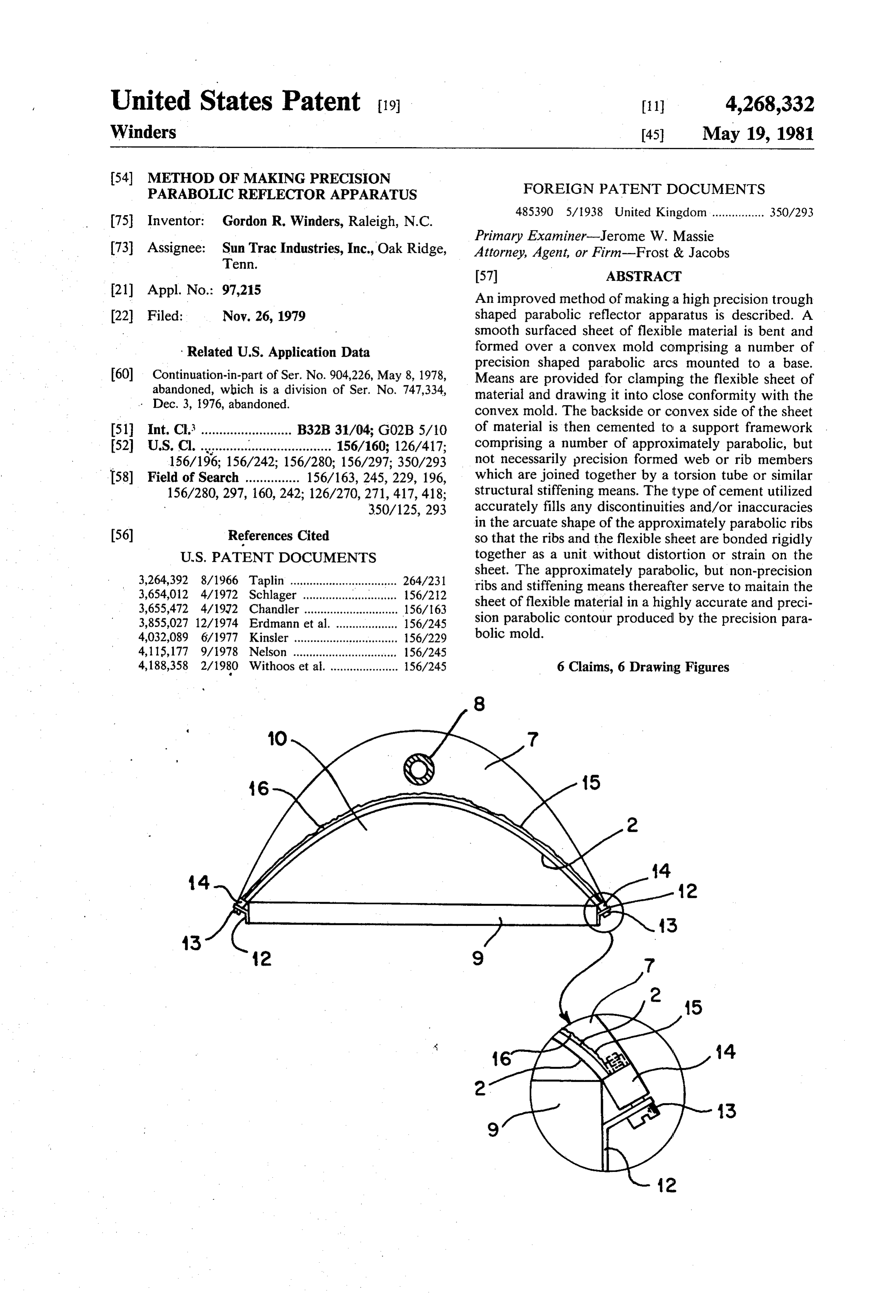
21) Appl. No.: 97.215 An improved method of making a high precision trough 22) Filed: Nov. 26, 1979 shaped parabolic reflector apparatus is described. A smooth surfaced sheet of flexible material is bent and
Related U.S. Application Data formed over a convex mold comprising a number of precision shaped parabolic arcs mounted to a base.
60 Continuation-in-part of Ser. No. 904,226, May 8, 1978, Means are provided for clamping the flexible sheet of abandoned, which is a division of Ser. No. 747,334, material and drawing it into close conformity with the . Dec. 3, 1976, abandoned. convex mold. The backside or convex side of the sheet (51) Int. Cl.......................... B32B 31/04; G02B 5/10 of material is then cemented to a support framework (52) U.S. C. ................................. 156/160; 126/417; comprising a number of approximately parabolic, but 156/196; 156/242; 156/280; 156/297; 350/293 not necessarily precision formed web or rib members 58) Field of Search ............... 156/163, 245, 229, 196, which are joined together by a torsion tube or similar 156/280, 297, 160,242; 126/270,271, 417,418; structural stiffening means. The type of cement utilized 350/125, 293 accurately fills any discontinuities and/or inaccuracies in the arcuate shape of the approximately parabolic ribs 56) References Cited so that the ribs and the flexible sheet are bonded rigidly
sheet. The approximately parabolic, but non-precision 3,264,392 8/1966 Taplin ................................. 264/231 ribs and stiffening means thereafter serve to maitain the 3,654,012 4/1972 Schlager ... ... 156/212 sheet of flexible material in a highly accurate and preci 3,655,472 4/1972 Chandler ............................. 156/163 3,855,027 12/1974 Erdmann et al. ................... 156/245 sion parabolic contour produced by the precision para 4,032,089 6/1977 Kinsler ................................ 156/229 bolic mold.
4,115,177 9/1978 Nelson ............ ... 156/245 4,188,358 2/1980 Withoos et al. ..................... 156/245 6 Claims, 6 Drawing Figures
Page 2
Drawing sheet — no readable text.
Page 3
Drawing sheet — no readable text.
Page 4
Drawing sheet — no readable text.
Page 5
An attempt to alleviate the expense and difficulty of
METHOD OF MAKING PRECISION PARABOLIC forming parabolic trough collectors utilizing a frame REFLECTORAPPARATUS work with numerous high precision parabolic ribs is shown in U.S. Pat. No. 3,959,056 in which a method of
CROSS-REFERENCE TO RELATED forming parabolic panels using honeycomb panels, APPLICATIONS foamed plastic, glass fibers, and impregnating resin is This application is a continuation-in-part of applica shown in which a continuous trough can be continu tion Ser. No. 904,226, filed May 8, 1978, now aban ously molded to any length desired. Very expensive and doned, which in turn is a division of application Ser. 10 complex equipment is required for such a forming tech nique and the resulting parabolic surface of the trough
shaped collector may be subject to thermal distortion or
TECHNICAL FIELD other mechanical difficulties because of the nature of This invention relates to solar collector apparatus in the materials utilized.
general and to parabolic trough shaped reflecting con 15 Another approach to reducing the cost of making centrators in particular. It relates specifically to a ofreflectors has been to substantially sacrifice the degree method of forming precision shaped parabolic trough precision used in manufacture by using simplified reflectors. molds on which the reflector's parabolic face is formed. Erdman, et al, U.S. Pat. No. 3,855,027, uses an air
BACKGROUND ART inflated mold of flexible material on which a sheet of fiber reinforced polyester resin is fabricated by conven
Since at least 1882, as shown in U.S. Pat. No. 257,580 20 tional issued to Ditzler, parabolic trough shaped reflectors spray lay-up technique. This sheet is then ren have been utilized to track the diurnal movements of the dered suitably stiff and rigid by incorporating reinforc ing sun to focus the image of the sun upon a collection tube urethane,ribbing in a second layer consisting of foamed poly set at the focal point along the axis of focus for such a 25 reinforcedfollowed polyester.
by a third layer of spray lay-up fiber
Even though the structure may reflector. Since this early date, many attempts have retain reasonable rigidity in use, the vital precision re been made to provide parabolic trough shaped concen quired in the reflector surface can be no greater than trators for solar energy and all have met with a greater or lesser degree of success. Of course, one of the pri that of the low pressure "balloon' on which it was formed (Column 4, lines 10-15) and this is given as a mary objects of the early art, which is continued for 30 surface accuracy of 0.060 inches rms, Column 3, line 43. ward to the present day, is the requirement that the collector be as faithfully parabolic as is possible or ob A similar technique is used by Chandler, U.S. Pat. No. 3,655,472, in which air pressure inflates an aluminum tainable since slight inaccuracies of curvature will move foil, the location of the focal point or axis off line, thus fiber which becomes the finished surface after layers of greatly reducing or eliminating the efficacy of such 35 up. In view of theresins reinforced well are applied, again by spray lay known shrinkage characteristics collectors. A second problem inherent in the prior art is of polymerization of resins during hardening, it is obvi the structural stability of the parabolic surface. Ideally, ous that precision must be lost when this warping reac it would be desirable that the parabolic surface be tion is resisted only by an air inflated elastic substrate. formed or hewn from a solid block of material so that
temperature variations, etc., would be uniformly com 40 manent mold, instead of air pressure, on which utilizes a rigid per pensated for and the line of focus for the trough shaped cate a parabolic shaped sheet made by applyingtoseveral fabri collector will remain unchanged.
In practice, the prior art has utilized structural frame layers of spray lay-up fiber reinforced thermosetting works with necessary stiffeners and arcuate ribs instead form theand plastic, finally vacuum depositing aluminum to reflector surface.
of the massive, expensive and unwieldy solid blocks of 45 Some approaches have been made to improve the material. For example, the Podolny patent. U.S. Pat.
No. 3,070,703, shows a solar power plant in which para precision, yet retain the use of low cost molding, by substituting foamed polyurethane or the like for the bolic trough shaped collectors utilize a structural frame air-inflated membrane as the form. Taplin, in U.S. Pat. and stiffeners to support parabolically curved reflecting No. 3,264,392 uses such a form, but in a male-female die surface. U.S. Pat. No. 2,141,330 also shows a parabolic 50 forming technique. Schlager, U.S. Pat. No. 3,654,012, trough shaped collector formed of a framework in applies a heat softened sheet of plastic over a preformed tended to maintain the structural uniformity and integ mold of foamed polystyrene, actually melting the sur rity of the resultant concentrator. face of the foamed plastic to create a bond with the Such structures require numerous, highly accurate sheet. Obviously these methods preclude any degree of parabolic arcuate support ribs which are expensive to 55 precision, first because it is not possible to precision make and which must be precise since the resulting form foamed plastic, and second because heating and form of the trough collector depends entirely upon the melting of the formed plastic alters the original con arcuate shape of the parabolic structural ribs. Some tours.
prior art devices have even resorted to adjustment In light of the foregoing difficulties mentioned with screws or tensioning means to vary the parabolic sur 60 regard to the prior art, it is an object of the present face for focusing reasons. A structure of this type is invention to provide an improved method of forming shown in British Pat. Specification No. 485,390 of May precision parabolic reflector surfaces of the trough type 19, 1938, in which an assembled structure of carefully for use as solar energy concentrators or collectors. machined ribs forms a concave mold to which a sheet of reflector material is permanently attached by fasteners. 65 DISCLOSURE OF THE INVENTION Much of the precision is lost because of eventual rack The foregoing and still other unmentioned objects of ing of the necessarily loose fit of bolt and rivets in the present invention are met by providing a precision drilled holes. convex parabolic mold over which may be formed a
Page 6
sheet of flexible smooth surfaced material. Many mate 10. Sun geometry image. rials such as glass fiber reinforced epoxy panels, bonded The design allocation of the maximum target error wood chip particle board, metal sheets, or any other band to the various attributes is a cost benefit exercise flexible and hard surfaced material may be used. The which dramatically affects the feasibility of certain con material is capable of being formed at least on one axis centrator arrangements and the cost of the system. of bending and is stiff enough in the opposite axis, trans The theoretical maximum efficiency attainable by verse thereto to provide some structural rigidity. The solar collectors is in excess of 90%. The maximum effi flexible sheet of material is tensioned by clamps to accu ciency attained in practice, requiring extremely high rately conform to the contours of the precision para and costly precision, is 86%. The method and apparatus bolic mold. A supporting framework comprising a num 10 of the present invention attains 84% efficiency without ber of approximately parabolic, by non-precision, sup recourse to expensive machining. Accordingly, as used port ribs joined together by a torque resisting tube or herein, the term “high precision' is understood to em other similar stiffener is then rigidly bonded, by a flow body tolerances exemplified by the following: able hardening cement, to the convex back surface of Longitudinal bow-0.040" in 16' the trough shaped collector sheet while it is in place 15 Longitudinal twist-15 minutes in 16 over the precision mold. When the cement has hard Contour error-0.015' max. ened, the interstacies between the non-precision support Fastener/glue shrink pull-0.003" max. ribs and the back surface of the precision formed sheet Local longitudinal surface of flexible material are intimately bonded together and errors-0.003" max.
filled by the flowable hardening cement so that even, 20 Local radius surface errors-0.001"/inch strong and continuous contact is achieved. The restrain One skilled in the art and familiar with machining ing clamps holding the flexible sheet to the precision practices would readily recognize that such tolerances mold may then be released and the sheet will be faith would ordinarily require unusually high precision in fully maintained in its formed curvature by the support fabrication techniques.
ribs and framework. The flowable hardening bonding 25 The preferred method of forming precision parabolic cement maintains precision contact between the non collectors of the trough style will be described together precision ribs and the precision arcuate surface pro with a preferred embodiment of the resulting apparatus. duced by bending the sheet over the mold. It should be clearly understood at the outset, however, DESCRIPTION OF THE DRAWINGS that the specific embodiment disclosed is capable of 30 many variations conventionally and otherwise which
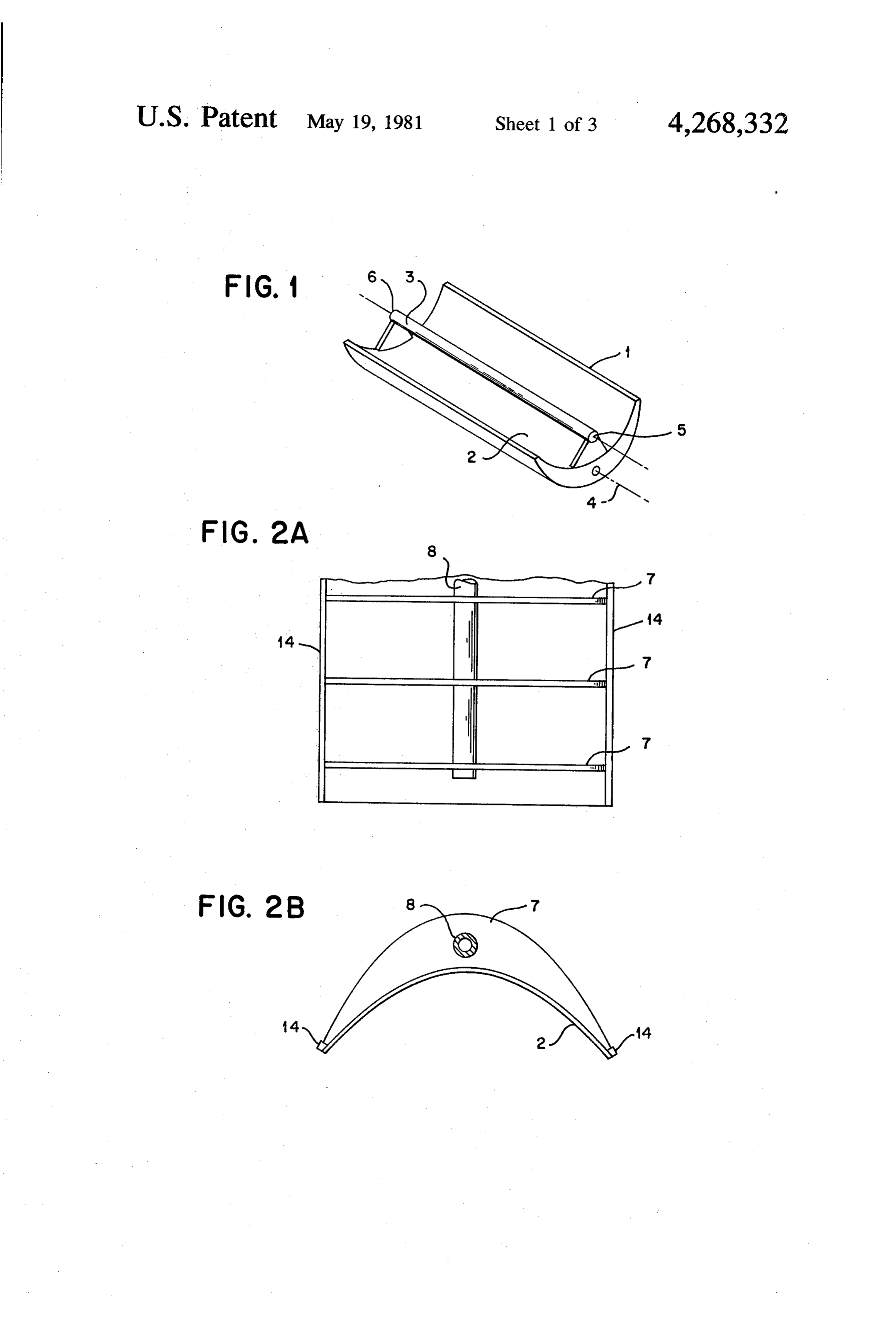
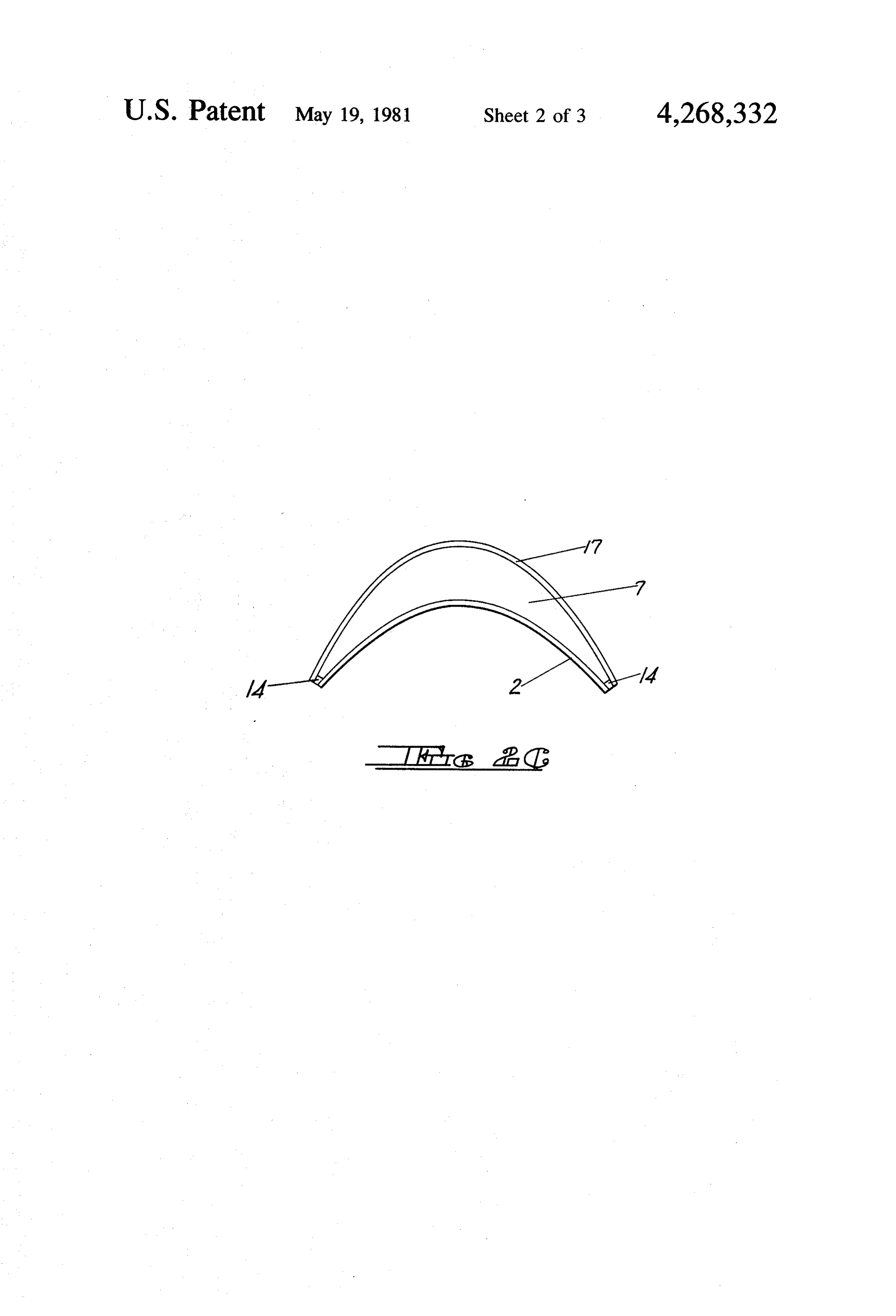
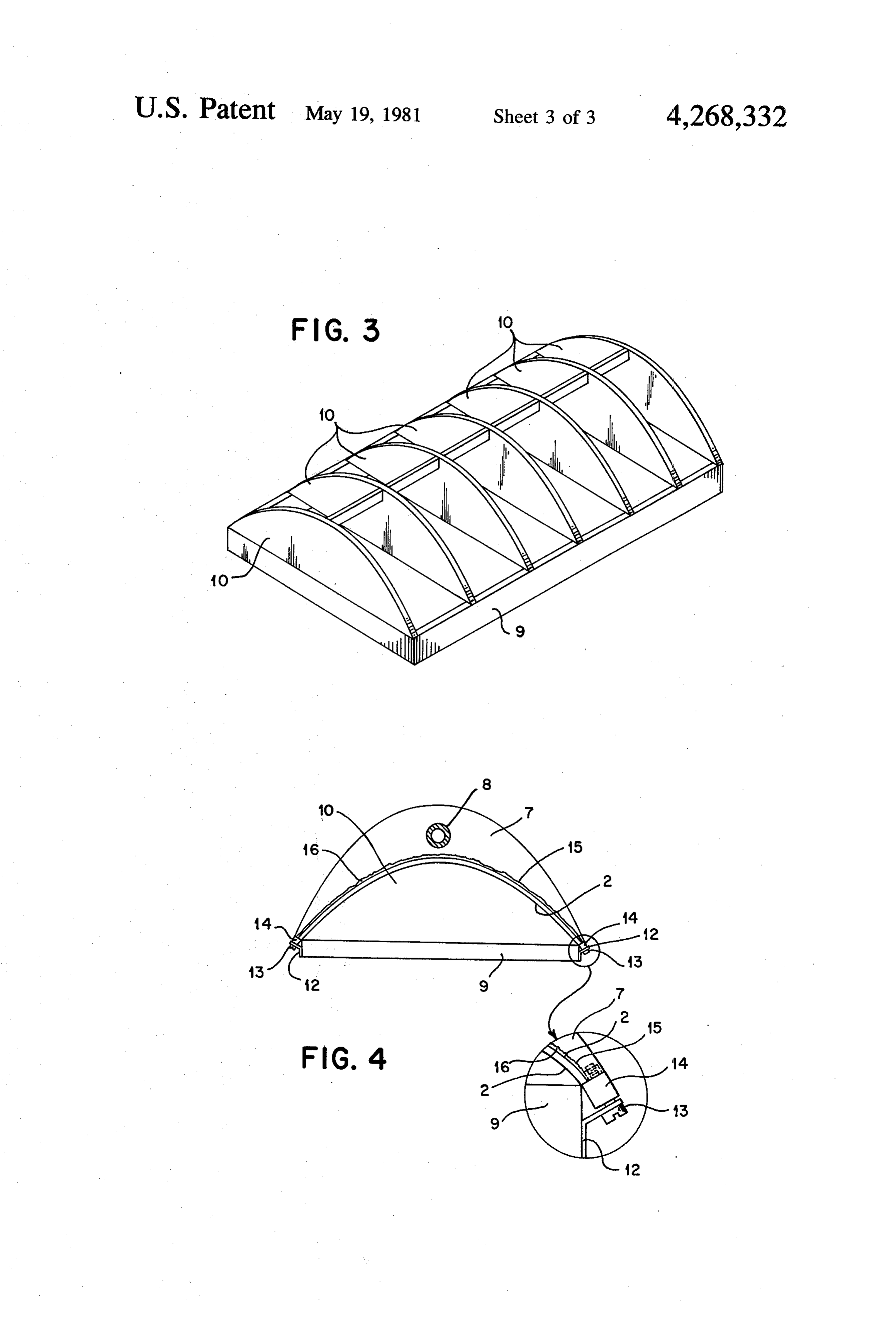
FIG. 1 illustrates an overall view of a typical para will be apparent to those of skill in the art and it is bolic trough collector of the general type intended in therefore not intended that the invention be in any way the present invention. limited by the specifics of the preferred embodiment FIG. 2A illustrates a backside, or convex side, of the described.
structure of the preferred embodiment constructed ac 35 The preferred embodiment and the preferred method cording to the techniques of the preferred method of of making the precision parabolic reflectors of the pres the invention. ent invention will be described with reference to the FIG. 2B illustrates an end elevation view of the struc aforementioned several figures of the drawing. ture shown in FIG. 2A. Proceeding now to a detailed description of the pre FIG. 2C illustrates an end elevation view of an alter 40 ferred embodiment and method of making precision native structure shown in FIG. 2A. parabolic trough shaped collectors or concentrators, FIG. 3 illustrates the preferred embodiment of a pre reference will be had to FIG. 1 in which a typical cision parabolic mold utilized in the preferred fabrica trough shaped parabolic solar concentrator is illus tion technique. trated.
FIG. 4 illustrates the preferred method of forming 45 Parabolic reflector 1 comprises a precision formed precision parabolic reflectors according to the present parabolic reflecting surface 2 elongated in the direction invention. of its focal axis to form a trough. The rays of the sun are DETAILED DESCRIPTION OF THE caused to focus and form an image of the sun along the INVENTION collector tube 3 which is generally a high temperature, SO high pressure resistant material for conducting the flow
The parabolic solar concentrator has a number of of a primary collection liquid as is well known in the art. physical attributes which contribute to the total error in Typical inlet means 5 and outlet means 6 are provided focusing the solar radiation beam on the collector/tar to the collection tube 4 as shown, but the details of the get, such as: apparatus for providing a flow of fluid through the 1. Surface irregularities in the reflective material. 55 collection zone in collection tube 3, being well known 2. Small surface distortions, such as local fastener in the art, are omitted for the sake of brevity. The pull. trough shaped collector 1 is generally provided with Contour errors. means for tracking the sun about an axis 4 and some Longitudinal straightness errors. times two axes of tracking freedom may be provided if Static longitudinal twist in the structure. desired as is also well known in the art. With this brief . Wind and position induced surface distortions. overview of the intended resultant structure, reference Coupling back-lash between the tracking control will be had to FIG. 2A.
ler and the reflector. In FIG. 2A, the schematic structure of the preferred 8. Cumulative coupling back-lash and torgue tube embodiment of the collector formed according to the wind-up errors in multiple satellite concentrators 65 present method is shown in which the backside (convex which are driven by connecting torque tubes to the side) of the precision parabolic surface 2 is shown sup master concentrator. ported by a series of generally parabolic support ribs 7 9. Deadband in the two direction tracking controller. which are rigidly joined together by a steel torque re
Page 7
sisting tube 8. An edge reinforcement strip and clamp bolic ribs 10 are joined together by spacers 11 made of ing means 14 are affixed to edges of the flexible sheet of dimensional 2X6 inch lumber and the entire assembly is material which forms the precision parabolic surface 2. rigidly bonded and screwed together in the preferred Strips 14 may be wood or metal as desired and may be embodiment to provide a rigid and stable mold surface bonded, screwed, or nailed to the flexible sheet of mate as defined by the outline of the arcuate ribs 10. Steel, rial 2. The purpose of edge reinforcing strips 14 will aluminum or other durable materials would serve appear below. equally well in the making of a mold. This convex mold Turning to FIG. 2B, an end elevation view of the is utilized as a stretcher frame for forming the flexible structure shown in FIG. 2A is illustrated, In FIG. 2B, it sheet 2 as will be described below. may be clearly seen that the reinforcing and support O Turning to FIG. 4, the mold of FIG.3 is shown in the webs or ribs 7 are in approximately continuous contact end elevational view so that the end of base 9 and the with the back surface of the precision parabolic surface end-most precision parabolic rib 10 are visible. A clamp 2 which is formed of a sheet of flexible material in a device is shown comprising an angle iron bracket 12 manner to be shown below. The steel reinforcing torque rigidly affixed on each side of base 9 which has a hole tube 8 is rigidly bonded to all of the various support ribs 15 through which a threaded screw 13 can slide freely. or webs 7 to take up longitudinal torsional variations Each threaded screw 13 engages with a threaded nut which would tend to distort the curvature of the reflec backing up against the surface of the edge reinforcing tor surface 2. stringer 14 illustrated and described with relation to In the preferred embodiment, the flexible sheet of FIG. 2a, Stringer 14 is, as noted earlier, bonded and material used to form the reflector surface 2 is a sheet of 20 screwed to the edge of the flexible sheet 2. Individual bonded and compressed wood fiber of the type gener clamp means 12, 13 and 14 with the cooperating nut, ally known under the trade name tempered Masonite. shown in the enlarged small view, are located every 4 However, other suitable materials would be flexible inches (more or less) along the entire length of the steel or aluminum sheets, plastic or glass fiber and resin trough shaped panel 2 so that uniform and exact bend impregnated material in sheet form, plywood or other 25 ing tension can be produced in sheet 2 to draw it into generally flexible not hardsheet material which is bend intimate conformity with the precision formed para able in at least one axis of bending and relatively imper bolic ribs 10. Camming action clamps, screw clamps or vious to the elements. The reinforcing ribs 7 are prefera any of a variety of clamps readily available could be bly resin bonded particle board of or inch thickness thus used. Once sheet 2 has been drawn into intimate or plywood with the marine environment grade bond 30 and exact conformity to the shape of the precision ribs ing glue utilized in their construction. Such materials 10, the support framework comprising numerous sup are utilized for their temperature stability, resistance to port ribs 7 to be bonded and bolted to the steel torque moisture and low cost and weight. Steel torque tube 8 is tube 8 and described previously with relation to FIGS. a 2 to 4 inch diameter steel well casing or similar steel or 2a and 2b, can be brought into position as shown and high strength tube of the thin-walled type, and it is 35 bonded, using a relatively thick layer of cement, such as bonded to the ribs 7 by a polyester resin or epoxy resin epoxy or polyester resin in the preferred embodiment, cement in the preferred embodiment and may also be to the back or convex surface of sheet 2. The entire mechanically fastened to the ribs. The reflector surface resulting assembly may be left for the cement to cure. It is formed on the concave side of sheet 2 by utilizing thin should be pointed out and emphasized that the reinforc aluminized polyester polyamide, or similar sheets com ing ribs (or webs) 7 need not be of a precision parabolic mercially available and well known in the art which shape and, indeed, it is a major object of the present have an adhesive backing or which may be cemented in invention to avoid the necessity of having precision place to faithfully duplicate the precision parabolic cutting and forming operations beyond those necessary shape of the surface 2 and to reflect the sun toward the to construct the initial precision mold. To that end, an focal point as shown in FIG.1. Such details, being well 45 exaggerated rough under surface of the rib 7 is illus known in the art, will not be described further. trated as rough surface 15 for each rib 7. Numerous FIG. 2C shows an alternate preferred embodiment of intersticies and arcuate discrepancies are shown in exag the bracing means wherein the torque tube 8 is omitted gerated form, but are filled with a flowable and harden and instead a flexible sheet 17 of bendable material, such able epoxy or polyester cement illustrated as cement as Masonite or sheet aluminum, is secured to the convex 50 filler 16 so that the resultant bond between ribs 7 of the surface of rib 7, as by bonding or fasteners, whereby to non-precision, approximately parabolic shape and the form an internally rib reinforced structure or composite back or convex surface of the parabolic form of sheet 2 shell. is achieved. The cement or bonding agent 16 that is used Turning to FIG. 3, the preferred precision mold uti to attach the ribs 7 to the back side of the parabolic lized in the technique of the present invention is illus 55 sheet 2 is preferably of a type that does not, upon hard trated in schematic form. A rigid base framework 9 of ening or setting, draw or otherwise distort the precision the preferred type is constructed of 6' welded struc concave face of the sheet 2. The resulting webs (ribs 7) tural steel channel, but heavy timbers may be utilized. approximate constant beams in their deflection charac In the preferred embodiment, this base was formed of teristic so that the stresses in the flexible sheet are ap 6" structural channel heavily braced and cross-braced 60 proximately equally distributed. When cement 16 has and rigidly welded at all joints and at the corners. Base 9 cured, the intimate and continuous bond between the is precision levelled and rigidly mounted to the floor or roughly parabolic shape of rib 7 and the precision para similar stable platform so that a true plane for the edges of bolic shape of the back surface of sheet 2 is achieved the trough will be created. To this rigid base 9 are rigidly and the precision surface of sheet 2 is maintained accu mounted a number of precision formed arcuate rib panels 65 rately and faithfully upon the release of the clamping 10 made of inch resin bonded particle board or plywood means 12, 13 and 14. The finished form may then be braced and maintained in vertical orientation with supplied with polished aluminum sheets on the reflect respect to the base 9. The individual precision para ing side of precision form trough sheet 2 or, as described
Page 8
previously, a flexible aluminized plastic sheet may be desired accurate parabolic form to provide the superior adhered to the curved surface to form a reflective results known in the art to be achievable in the art with trough concentrator. If desired, the overall resulting this type of collector.
structure may be supplied with an overcoat of clear Having thus described my invention, its method of epoxy or similar sealer to seal out moisture and airborn manufacture, and the resulting structure with reference foreign materials. However, it will, of course, be under to the preferred embodiment and the several figures stood by one skilled in the art that the reflective, con described, what is claimed is:
cave parabolic base of sheet 2 may be inherent in the 1. A method of making trough-shaped high precision sheet itself, such as when using a sheet 2 of aluminum or parabolic reflectors, comprising the steps of: other polished reflective metal, or the reflective mate 10 bending a sheet of inelastic flexible material over a rial may be deposited on the sheet by the well known precision parabolically contoured trough-shaped vacuum depositing technique or by stick on adhesive rigid, convex mold fixture; backed high reflective material such as 3M-5400 reflec forcing said sheet of material into continuous and tive material. intimate contact with said mold fixture to tension As will be immediately appreciated by those of skill 15 said sheet of inelastic flexible material at the edges in the art, the present method for forming precision thereof which are parallel to the focal axis of said parabolic trough reflectors may be easily practiced mold fixture, thereby conforming said sheet into a without resort to expensive operations such as precision high precision parbolically curved trough-shape; forming of structural reinforcing ribs or precision mold centering a plurality of spaced apart, non-precision, ing of rigid or plastic materials (such as solid metal 20 reinforcing ribs to the convex surface of said flexi sheets bent to retain the parabolic shape) and a simple, ble material with a flowable and hard-curable ce unified and highly precision final form with high struc ment while it is so bent and forced into high preci tural integrity and resistance to deformation can be sion conformality with said mold fixture, said ribs achieved. Low cost materials and techniques are uti being affixed perpendicularly to said focal axis of lized throughout and panels of the desired trough shape 25 said parabolic trough and perpendicularly to said may be formed of varying lengths from a few feet to as convex surface at regular intervals along the axis of long as desired. said trough shape;
The precision arcuate mold ribs 10 were traced from curing said cement whereby the intersticies between a precision pattern full scale on 3 or 3 inch thickness said non-precision support ribs and the back sur particle board and all ribs cut. A pattern following 30 face of said precision formed sheet of flexible mate router following a precision steel pattern is preferred. rial are intimately bonded together and completely Another method is to simultaneously cut all of the ribs filled by the said hard-curable cement so that even, from a stack of rough formed pieces using a band saw strong and continuous contact is achieved; with final precision sanding to achieve true conformity removing the resulting parabolic trough-shaped to the exact parabolic curvature desired. Utilized as 35 sheet, maintained in high precision configuration they are, these ribs 10 are not subject to wear or deterio by said reinforcing ribs, from said mold fixture; and ration and may be used indefinitely once they have been providing the concave precision curved parabolic mounted to the base 9 as shown. If desired, steel mold surface of said sheet with light reflective capability, pieces for the ultimate in durability could be used. thus completing the formation of said high preci Other molding techniques, such as the well-known glass 40 sion parabolically curved trough-shaped reflector. fiber and resin lay-up or spraying techniques, require 2. The method as described in claim 1, wherein said continuous surface precision molds which are expensive flexible material is aluminum and said light reflective to produce initially and require continual refinishing or capability of said concave precision curved parabolic resurfacing due to deterioration in the surface after surface is polished aluminum.
repeated use and are thus of lesser utility that the pre 3. The method as described in claim 1, wherein said ferred method described. Another obviously equivalent concave precision curved parabolic sheet is provided molding technique would be to use a concave precision with light capability by depositing reflective material mold structure (the converse of FIG. 3) and to push the thereon by vacuum deposition.
flexible sheet into tight conformity with the mold ribs. 4. The method as described in claim 1, wherein said However, this technique would make the attachment of 50 concave precision curved parabolic sheet is provided the support framework and arcuate ribs more difficult with light capability by depositing stick on adhesive and the details of the mold to allow such application backed reflective material thereon.
steps would be much more complex. 5. The method as described in claim 1 further com As noted earlier, the reinforcing support ribs 7 of the prising a step of framework which support the formed panel sheet 2 55 joining said plurality of said reinforcing ribs together need not be precision formed but may be rough cut to by a stiffening member affixed thereto, said stiffen the approximate outline desired. This leaves to the flow ing member being generally parallel with said focal able and hardening bonding cement the task of produc axis of said parabolic surface. ing a uniform and true conformance between the back 6. The method as described in claim 1 further com surface of the precision formed panel 2 and the non 60 prising a step of:
uniform, non-precision formed undersurface of the ar joining said plurality of said reinforcing ribs together cuate ribs 7. This greatly reduces the cost and complex by a stiffening member affixed thereto, said stiffen ity in forming the collector apparatus since none of the ing member comprising a flexible sheet secured to assembly techniques or elements need be precision op the convex surface of each said rib, whereby to erations once the precision mold has been made. Yet the 65 form an internally rib reinforced structure or com resulting parabolic trough shaped concentrator is a posite shell.
highly precision surface which faithfully mirrors the k k ck ck sk
Provenance
- Collection
- Cited prior art
- Original PDF
- patentimages.storage.googleapis.com →
- Filed
- 1979-11-26
- Pages
- 8
- Method
- pdftotext (the PDF's own text layer) + pdftoppm 300dpi page scans
- Source
- Google Patents bibliographic record
- Granted
- 1981-05-19
- Inventors
- Gordon R. Winders; Sun Trac Industries Inc
- Transcribed from
- patentimages.storage.googleapis.com →