patent · US4081966
Solar operated closed system power generator
4 April 1978
Page 1 — bibliographic record
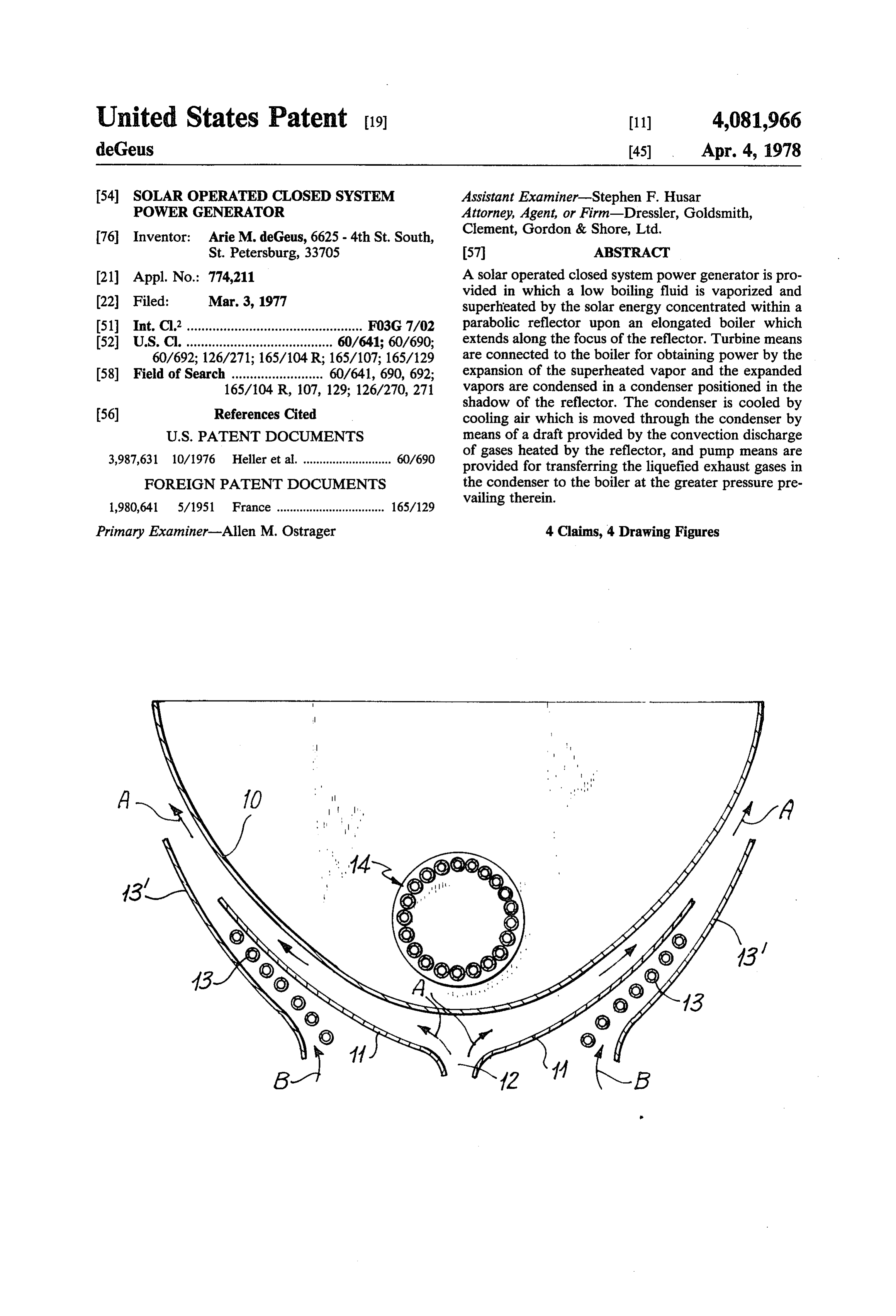
United States Patent (19) (11) 4,081,966 deGeus 45 Apr. 4, 1978 54). SOLAR OPERATED CLOSED SYSTEM Assistant Examiner-Stephen F. Husar POWER GENERATOR Attorney, Agent, or Firm-Dressler, Goldsmith, 76 Inventor: Arie M. deGeus, 6625 - 4th St. South, Clement, Gordon & Shore, Ltd. St. Petersburg, 33705 57 ABSTRACT 21 Appl. No.: 774,211 A solar operated closed system power generator is pro vided in which a low boiling fluid is vaporized and 22 Filed: Mar. 3, 1977 superheated by the solar energy concentrated within a 51) Int. Cl’................................................ FO3G 7/02 parabolic reflector upon an elongated boiler which 52 U.S. C. ........................................ 60/641; 60/690; extends along the focus of the reflector. Turbine means 60/692; 126/271; 165/104 R; 165/107; 165/129 are connected to the boiler for obtaining power by the 58) Field of Search ......................... 60/641, 690, 692; expansion of the superheated vapor and the expanded 165/104 R, 107, 129; 126/270, 271 vapors are condensed in a condenser positioned in the
shadow of the reflector. The condenser is cooled by cooling air which is moved through the condenser by
3,987,631 10/1976 Heller et al. ........................... 60/690 of gases heated by the reflector, and pump means are provided for transferring the liquefied exhaust gases in
FOREIGN PATENT DOCUMENTS the condenser to the boiler at the greater pressure pre 1,980,641 5/1951 France ................................. 165/129 vailing therein.
Primary Examiner-Allen M. Ostrager 4 Claims, 4 Drawing Figures
Page 2
Drawing sheet — no readable text.
Page 3
which is constituted by a plurality of copper tubes
SOLAR OPERATED CLOSED SYSTEM POWER welded together to form a ring as pictured in FIG. 1. GENERATOR The use of small tubes in a circular body increases the heat transfer surface area approximately three fold.
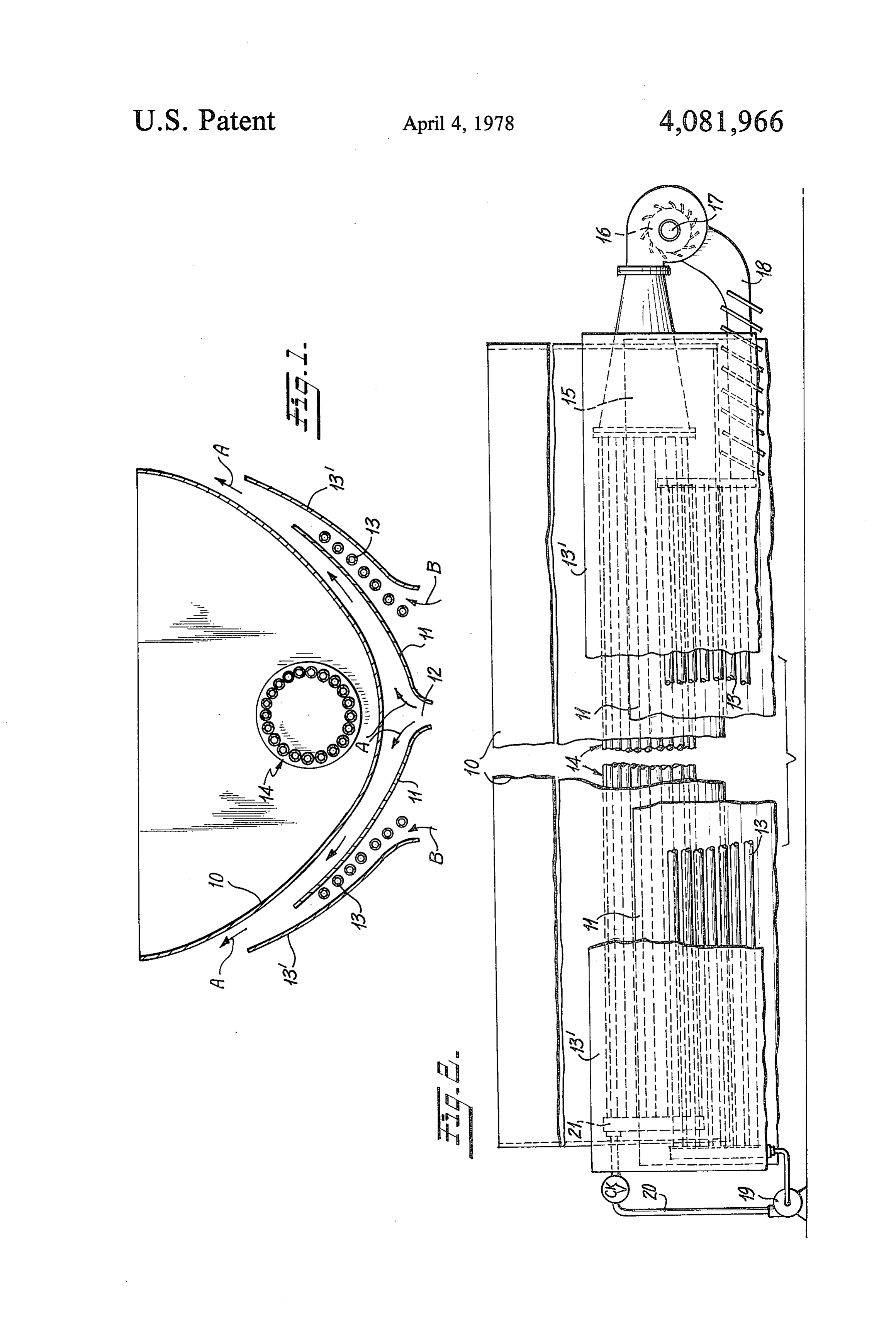
The present invention relates to solar operated closed The superheated gases produced in the heat collector system power generators in which a low boiling fluid is 14 (which serves as a boiler and superheater) are sup vaporized and superheated by the solar energy concen plied to a turbine inlet housing 15 which leads to a trated within a parabolic reflector to provide super centrifugal turbine 16 which operates a shaft 17 from heated fluid at elevated pressure for the operation of a which external power can be obtained. The reduced turbine and the exhaust gases from said turbine are 10 pressure gases exhausting from the turbine 16 enter a condensed to liquefy the same by cooling air which is duct 18, and these gases are still superheated to a small moved through the condenser by means of a draft of air extent since efficient operation of the turbine is facili provided by the convection discharge of gases heated tated by avoiding condensation therein. While a centrif. by the reflector. ugal turbine is pictured, other turbines can be used, The effort to transform solar energy into useful form 15 especially in larger installations. The turbine can be has considered diverse opportunities, but one of the single or double stage turbines depending on the pres most promising involves a closed system power genera sure ratio which would normally range from 4.5:1 to tor in which a low boiling fluid, such as a fluorinated 6:1.
hydrocarbon, is vaporized by solar energy and used to The exhaust duct 18, which may have fins thereon to drive a turbine. In this invention, the heat needed to 20 air cooling, empties into condenser 13 which is posi vaporize and superheat the low boiling fluid is supplied tioned and air cooled as previously described. by a parabolic reflector and the condenser is cooled by It should be observed that the heat collector 14 is at means of air which is moved through the condenser by a slight angle to the horizontal so that any vapor bub means of a draft of air provided by the convection dis bles are forced to move rapidly toward the turbine charge of gases heated by the reflector. In this way, the 25 which optimizes heat transfer. The condenser 13 is also reflector provides both the heat and the cooling re at a slight angle so that condensed fluid gravitates quired by the different portions of the closed system toward a pump described below.
power generator. The liquid formed by condensation in the condenser The invention will be more fully understood from the 13 is withdrawn therefrom by a pump 19 which forces accompanying drawings in which; 30 the liquid through line 20 and discharges it into a header FIG. 1 is a diagrammatic cross-section of a parabolic 21 at the inlet end of the heat collector 14 which is the reflector provided with an elongated boiler and a con boiler of the system. The pressure in the collector 14 is denser in accordance with this invention; and about 8-9 atmospheres in typical operation and the FIG. 2 is a diagrammatic side elevation showing a condenser pressure is typically 1.7 atmospheres so that power generating system which is appropriate for use 35 the pump must be selected to work against this pressure with the reflector-boiler-condenser combination shown differential. The pump 19 can be geared to the turbine in FIG. 1. shaft 17 or can be driven electrically using a portion of Referring more particularly to the drawing, 10 identi the power which is generated by the system. fies a parabolic reflector. Beneath the reflector 10 are The reflector's size and length should be related to shields 11 which are open to the atmosphere at the base the length and size of the boiler and also to the speed of of the reflector as indicated at 12. As a result, when movement of fluid through the system and the operat solar energy is received by the reflector, some of this ing pressures so as to insure that the low boiling liquid energy heats the material of the reflector and this cre is vaporized and superheated to a considerable extent ates a chimney effect in which air is drawn in through since the vapor in the turbine cannot be allowed to openings 12 near the base of the reflector and is moved 45 condense.
upwardly between the reflector 10 and the shields 11. The system is started by operating the pump 19 to This movement of air is shown by arrows A. The con supply fluid in liquid form to the elongated boiler. This denser 13 is housed outside of the shield 11 and within can be automatically actuated by a thermostat which a housing 13. The movement of air shown by arrows A senses the temperature within the boiler. induces a movement of cooling air through the con 50 Suitable low boiling fluids are fluorinated hydrocar denser 13 as shown by arrows B. The shields 11 prevent bons which are available in commerce. the heat of the reflector 10 from reaching the condenser It is desired to stress that the condenser 13 is air 13. At the same time, the bulk of the solar energy is cooled and a considerable volume of cooling air must be concentrated at the heat collector 14 which provides an passed over the tubes of the condenser in order to pro elongated boiler extending along the focus of the reflec 55 vide the needed cooling for the simple reason that air is tor. not an efficient coolant because of the poor coefficient As will be appreciated, the reflector may be moved to of heat transmission through an air-metal interface. keep it pointed toward the sun, and the condenser 13 is Such a large volume of air would require fans to pro positioned to keep it in the shadow of the reflector. duce a forced draft, and the expense and inefficiency It will be understood that the chimney construction introduced by the operation of such fans would be quite shown in FIG. 1 is merely illustrative, and it is only detrimental.
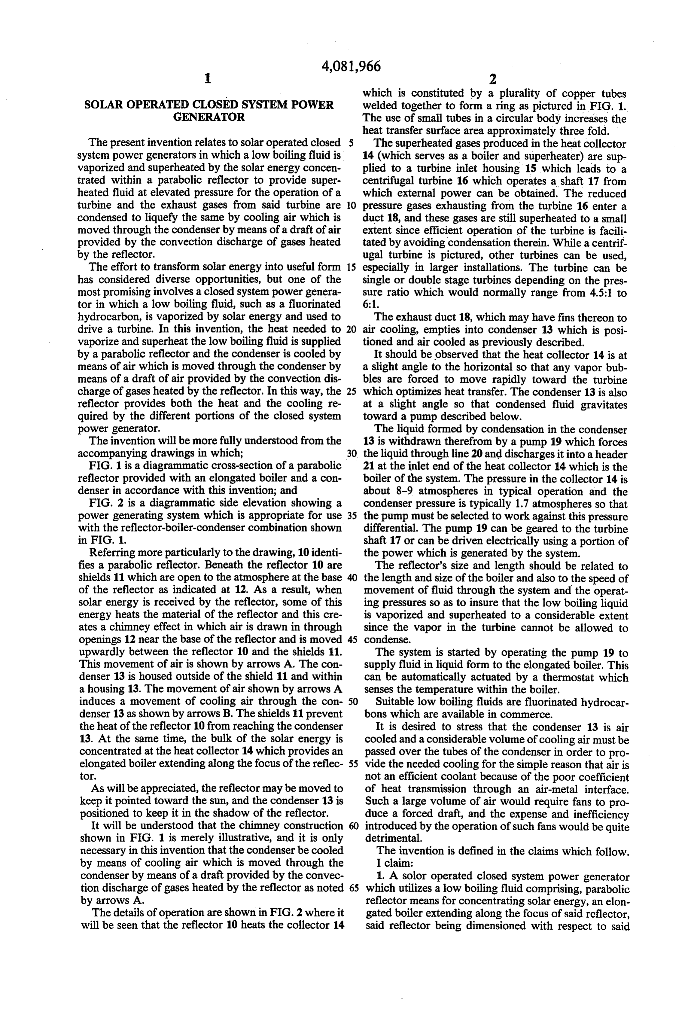
necessary in this invention that the condenser be cooled The invention is defined in the claims which follow. by means of cooling air which is moved through the I claim:
condenser by means of a draft provided by the convec 1. A solor operated closed system power generator tion discharge of gases heated by the reflector as noted 65 which utilizes a low boiling fluid comprising, parabolic by arrows A. reflector means for concentrating solar energy, an elon The details of operation are shown in FIG. 2 where it gated boiler extending along the focus of said reflector, will be seen that the reflector 10 heats the collector 14 said reflector being dimensioned with respect to said
Page 4
boiler to vaporize the liquid which is supplied to said said shield means extending upwardly along at least one boiler against the elevated pressure prevailing therein, side of said reflector so that the heat of the reflector and to superheat the vapor so-produced, turbine means heats air between the reflector and said shield means to connected to said boiler for obtaining power by the create a draft of air, housing means positioned outside of expansion of said superheated vapor, means to convey 5 said shield means so that said draft of air induces move the exhaust from said turbine to condenser means posi ment of cooling air through the space between said tioned in the shadow of said reflector, said condenser housing means and said shield means, said condenser serving to liquefy the exhaust gases obtained from said being positioned within the space between said housing turbine, said condenser being cooled by means of cool means and said shield means.
ing air which is moved through the condenser by means 10 3. A solar operated closed system power generator as of a draft provided by the convection discharge of air recited in claim 1 in which said elongated boiler and heated by said reflector, and pump means for transfer said condenser are each positioned at a slight angle to ring the liquefied exhaust gases in said condenser to said the horizontal, boiler at the greater pressure prevailing therein. 4. A solar operated closed system power generator as 2. A solar operated closed system power generator as 15 recited in claim 1 in which said elongated boiler is con recited in claim 1 in which shield means are provided stituted by a plurality of tubes secured together to form beneath said reflector and spaced therefrom, said shield a ring.
means having an air inlet at the base of the reflector and k is k
Provenance
- Collection
- Cited prior art
- Original PDF
- patentimages.storage.googleapis.com →
- Filed
- 1977-03-03
- Pages
- 4
- Method
- pdftotext (the PDF's own text layer) + pdftoppm 300dpi page scans
- Source
- Google Patents bibliographic record
- Granted
- 1978-04-04
- Inventors
- Arie M. deGeus
- Transcribed from
- patentimages.storage.googleapis.com →