patent · US2255672
Electrical control device
9 September 1941
Page 1
Drawing sheet — no readable text.
Page 2
Drawing sheet — no readable text.
Page 3
Patented Sept. 9, 1941 2,255,672
UNITED STATES PATENT OFFICE
ELECTRICAL CONTROL DEVICE
William C. Mason, Albany, N. Y.
Application July 1, 1938, Serial No. 216,911
My invention particularly relates to an elec Switch associated therewith, said element being trical control which is primarily adapted for use capable of being placed within a combustion with fluid fuel burners and which is characterized chamber or where temperatures of high order by its simplicity, low cost of manufacture and by exist under burner operating conditions whereby the fact that it will completely control the opera due to the thermal-responsive character of the tion of a fuel burner whereby to insure safety in element it will operate with extreme rapidity to its operation under all conditions. effect a desired operation of the control elements In the control of fuel burners, for example, with which it is associated. A further object, oil burners, it is necessary where they are ar therefore, resides in providing a control device ranged for automatic control to provide means 0 which comprises an element of the foregoing which is operable to shut off the burner in the character.
event that, during an operation thereof, the Further objects of my invention reside in the burner flame is extinguished for some reason or provision of a control unit comprising an elec other, or, when the burner is initially placed in trically controlled switch which, preferably, com operation, following a shut-off period, ignition prises a bimetallic element operable in response of the fuel fails to take place. Such means to heat generated by electrical means to close or should not only be positive in Operation but open an electrical circuit. A switch construction should also operate very rapidly so that the of this character entails a low manufacturing burner is shut off, in the event of a failure of 20 cost speeds and yet comparatively slow, predetermined of operation of the switch may be effected burner operation, before a sufficient period of so that where such a bimetallic element or a plu time has elapsed to permit a dangerous condition rality thereof are employed to open or close a to be created such as the formation of explosive mixtures. Such rapid operation will also shut circuit through two or more pairs of contacts, as off the burner, in event of failure, before an ap herein contemplated, one of a pair of contacts preciable quantity of liquid fuel is deposited in may be actuated in timed relation to a second the combustion chamber, an occurrence which movable contact to make or break an electrical would produce uncleanliness and undesirable circuit therethrough.
odor, and would cause smoking when the burner A still further object resides in providing, in a was next placed in operation. control device, a switch element of the above It is therefore a first object of my invention 30 character which is so arranged that the degree to provide a control device, adapted to be used to which the bimetallic element may be warped With a fluid fuel burner, which device, though is limited, thereby preventing excessive strains simple in construction, will completely and posi being set up in the element after an electrical tively control the operation of the burner and 35 contact has been made thereby, which might which device is characterized by its rapidity of otherwise produce deformation therein and im operation in that it will shut off the burner in pair the designed operation thereof with respect such a short interval of time that all dangers to timing.
due, for example, to the formation of explosive Another object of my invention resides in the mixtures are entirely obviated. For example, a 40 provision of a switch comprising a bimetallic element of the foregoing character which is so burner which is controlled by a control device of the character herein contemplated can be shut constructed that said bimetallic element will off in the event ignition fails to take place or for operate to close a circuit through a pair of co any other cause combustion fails or does not oc operative contacts and exert a force substantially cur within a period of the order of a few Seconds 45 sufficient only to hold said contacts firmly in from the time of starting an operation of the engagement so that said contacts will be sub burner or from the moment combustion ceases. stantially instantaneously parted when the cir Therefore, an appreciable amount of fuel Will cuit is open to the electrical heating means as not be deposited in the combustion chamber sociated with said bimetallic element. thereby substantially eliminating any odor of the 50 With these and other objects in view, my inven fuel, smoking and unclean burner conditions. tion includes the novel elements and the combi An important feature of my invention lies in nations and arrangements thereof described be the provision of a thermal-responsive element low and illustrated in the accompanying draw which will expand and contract rapidly under ings, in which varying temperature conditions and, at the same Fig. 1 is an elevation view of one form of my time, exert sufficient force to operate a control 55
Page 4
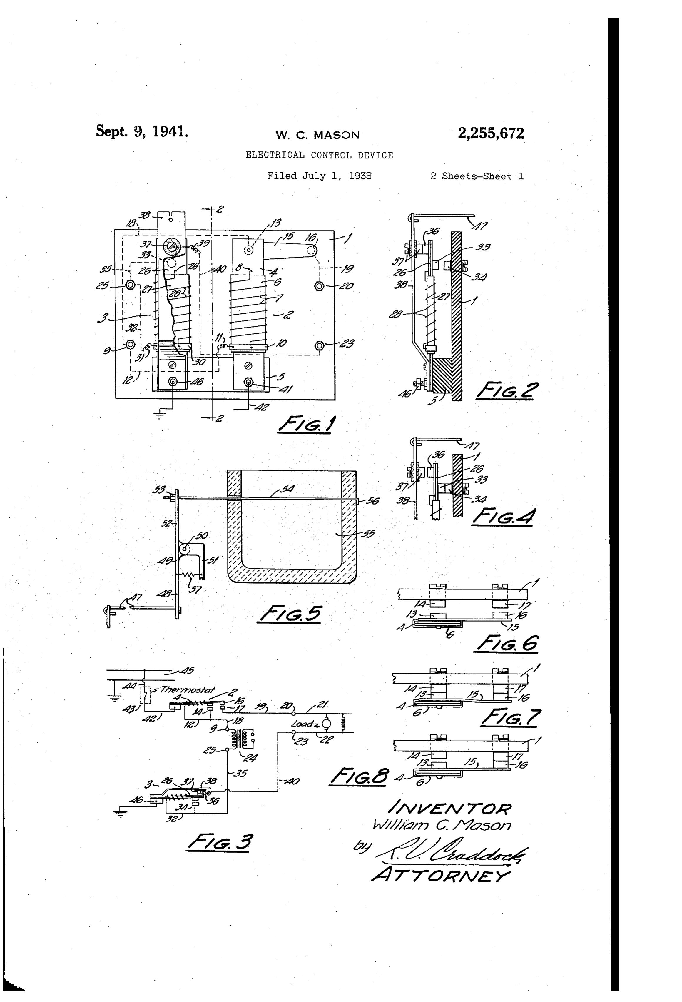
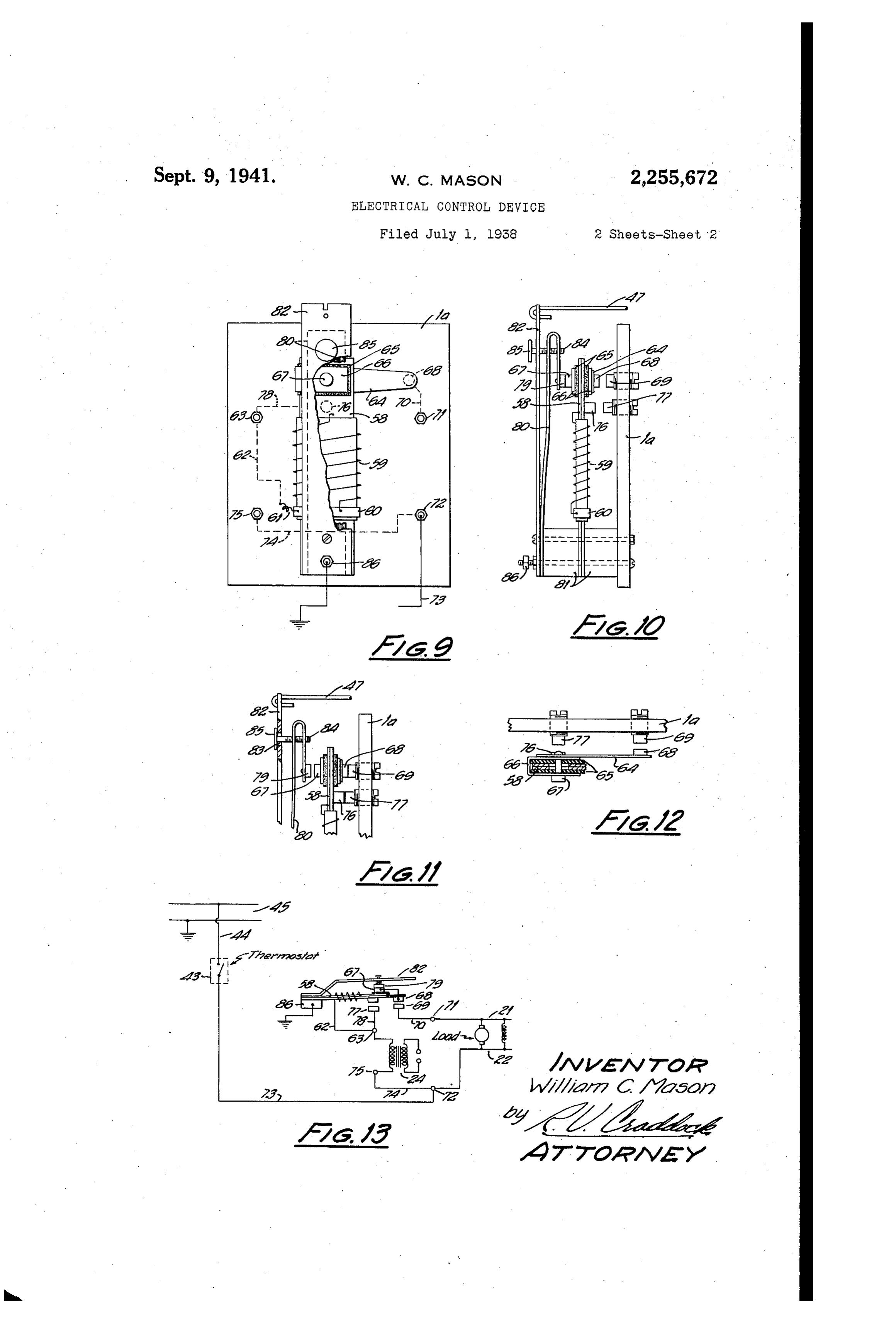
control device with a portion of one element tact is electrically connected through a con thereof broken away; ductor 9 to a terminal 2. Fig. 2 is a sectional elevation view tiereof The various electrically operated parts of a taken in about the plane 2-2 of Fig. 1; fuel burner are herein referred to as the elec Fig. 3 is a wiring diagran illustrating the elec 5 trical load of the bul'nei and, by w8y of example, trical interconnection of my control device with illustrated as a motor and inductance in the Wir an electrical load; ing diagram of Fig. 3. One side of this load is Fig. 4 is a fragmentary view, partially in Sec adapted to be connected thirough conductor 2 tion, illustrating the switch element shown in to terminai 2 and the other side of said load Fig. 2 in an alternative position; 10 through conductor 22 to terminal 23. Likewise, Fig. 5 illustrates One manner of aSSociating the the primary of an ignition transformer 24 for device of Fig. 1 with a thermal-responsive ele Said burner is adapted to be connected between ment. the terminal 9 and a terminal 25. Hence, it will Fig. 6 is a fragmetary plan view of a part of the be seen, generally speaking, that the heating coil control panel and illustrating two pairs of con 15 is connected in the primary circuit of the trans tacts in relatively spaced position; former 2 and contacts S and it are designed Figs. and 8 are views similar to Fig. 6 but to control the flow of current to the conductor showing the contacts in the relative, positions 2. On one side of the load circuit. they will assume according to the degree of ac The SWitch 3 is similar to switch 2 in that it tuation of a bimetallic element associated there 20 comprises a bimetallic arm 26 surrounded by an with; insulating sleeve 27 which has wound thereabout Fig. 9 is an elevation view of a modified form a heating coil 28. One end of the heating coil of control device; is electrically connected to the arm 2e as indi Fig. 10 is a side elevation view thereof; cated at 29 and the other end thereof is con Fig. li is a fragmentary, side elevation view nected to terminal 25 through the medium of showing the switch arm in an alternative posi collar 38, lead 3 f and conductor 32. Arm 26 is tion; provided on the inner surface thereof with a con Fig. 12 is a fragmentary plan view thereof, par tact 33 which is adapted to engage a contact 34 tially in selection; and mounted in cooperative relation thereto on the Fig. 13 is a wiring diagram illustrating the 30 panell. Contact 34 is electrically connected with control device of Fig. 9 electrically interconnected terminal 25 through conductur 35. Arm 26 is With an electrical load. also provided with contact 36 which is mounted The control device illustrated in Figs. 1 to 8 On the outer surface thereof and designed nor inclusive comprises a panel which may be mally to lie in engagement with a contact 37 formed of any suitable electrical insulating ma 35 which is mounted upon, but electrically insulated terial and upon which is mounted a first switch from, a movable arm 33 which may be designed element indicated generally at 2 and a second to overlie the bimetalic arm 26. Contact 37 is Switch element indicated generally at 3. The electrically connected with terminal 23 by means switch 2 comprises a bimetallic arm 4 which is of a flex lead 39 and conductor 4. preferably mounted upon and secured to an in 40 From the foregoing, it should be apparent that sulating block 5 on the panel which serves pre in the heating coil 28, like heating coil 7, is included determinately to space the contacts borne by the primary circuit of the ignition transformer the bimetallic element from those contacts which 2 and that contact 3i is connected to one side are mounted upon the panel in cooperative rela of the load circuit of the burner. tion thereto. The arm 4 is, at least in part, Sur- . . Assuming, therefore, that terminai 4 of switch rounded by an insulating sieeve 6 about which is 2 which is in electrical contact with the arm 4 Wound a coil 7 of electrical resisting wire form thereof is connected through conductor 42, ther ing a heating element adapted when energized mostat 43 and conductor 44 to one side of a source to actuate the arm 4 or cause it to warp. One of electrical energy 45, that the other side of said end of the resistor 7 is electrically connected to 50 Source is grounded and that terminal 46 of switch the al'm as indicated at 8 and the other end 3, in electrical contact with arm 26 thereof, is thereof is electrically connected to a terminal 9 also grounded, it will be seen that, if the circuit by ineans of a collar f0, a lead it, and conductor through thermostat 3 is closed, a closed circuit 2, which may be arranged to extend through the Will exist including in series heating coils 7 and panel to the terminal 9. The bimetallic alm 4, 55 28 and the primary winding of the ignition trans is provided on the underside thereof with a con former 24. Furthermore, with the contacts 36 tact i3 (see Fig. 6) and panel i is provided with and 3 of switch 3 normally in engagement, a a contact 4 arranged to be engaged by contact circuit from the load to ground is completed but 3 When the arm 4, in response to heat generated contacts 6 and 7 of switch 2 are spaced apart. by coil , is warped. Arm 4 is also provided with 60 However, when the bimetalic arm 4 of switch a laterally extending arm i5, preferably of resil 2 warps due to the heat generated by coil 7, it ient material, and bearing a contact 6 which is Will close the circuit through contacts 6 and adapted to engage a contact 7 mounted on the and complete the electrical circuit to the load. panel? when arm 4 is warped as above described. At the same time, bimetallic arm 26 of switch 3 For a reason, which will hereinafter be apparent, Will also warp but Switch 2 is so designed that contacts 6 and 7 are preferably somewhat more 65 when the heating coil 7 thereof is energized it closely Spaced than contacts 3 and 4 so that an will warp to close the circuit through contacts f G electrical circuit will be closed through contacts and before the bimetallic arm 26 of switch f6 and fibefore contacts f3 and 4 engage each 3 is Warped sufficiently to open the circuit between other and the resilience of arm 5 permits this contacts 36 and 37 thereof and means are pro operation without producing appreciable torsion 70 vided, as described in the following, which func all stresses in the bimetallic arm. The contact tion to prevent a separation of the contacts 36 4 is electrically connected through a conductor and 37 in the event of proper burner operation 8, which nay be imbedded in the panel as ill but which will permit a separation thereof in the lustrated in dotted lines, to terminal 9 and con 75 event combustion fails to take place.
Page 5
The free end of arm 38 may be provided With of operation thereof would necessarily be ex a slot and an opening adjacent thereto as illus tremely slow. Such thermal-responsive elements trated in which one end of a rod 47 may be se are, therefore, of practically no value in a con cured, the other end of rod 47 being secured, as trol device where quick response and direct, posi illustrated in Fig. 5, to the arm 48 of a lever 49 tive control thereby are desired. which is pivotally mounted as at 50 in a bracket I have also provided means for limiting the 5. The other arm 52 of lever 49 has adjustably degree to which the respective bimetallic elements connected thereto by means of a nut 53 a ther of Switches 2 and 3 may be warped while main mal-responsive element or wire 54, the thread taining a circuit to the electrical load of the fuel ed end of which passes through an opening in 0. burner. These means comprises electrical con the arm 52. Element 54 is adapted to be placed tacts which Serve, when the bimetallic arms have Within the combustion chamber indicated gener been warped to a sufficient degree, to shunt the ally at 55 or in those spaces where temperatures heating coils associated therewith. Upon shunt. of high order exist during the operation of a ing of the heating coils, the bimetallic arms im burner. One end of wire 54 may be bent over mediately begin to cool and return to their nor as at 56 to Secure it to one side of the combustion mal position. However, in so doing, engagement chamber So that the wire extends thereacross between the contacts which serve to shunt the with its opposite end connected to arm 52 of coils is broken and, the coils being again ener lever 49. A spring 57 is preferably connected be gized, will again cause the bimetallic arms to tween the arm 48 of lever 49 and bracket 5 Warp. The contacts 3 and 4 of switch 2 effect whereby normally to urge the contact 37 carried this intermittent energization of the heating coil by arm 38 into engagement with contact 36 and and the resilient arm 5 serves to maintain con the degree to which the arm 38 may be moved tacts 6 and 7 in engagement during this opera by Spring 57 is dependent upon the thermal-re tion. Likewise, contacts 33 and 34 of Switch 3 Sponsive element 54. In the absence of combus serve to provide intermittent energization of coil tion in the combustion chamber, element 54 will 28. The electrical circuit of these contacts here permit Spring 57 to maintain contact 37 of arm 38 in before described, should be apparent from an in engagement with contact 36 during a portion examination of Fig. 3.
only of the movement of the bimetallic arm 26 The intermittent operation of the heating coils when it warps under the influence of heat gen T and 28 perform two functions. First, it pre erated by the coil 28. That degree of movement vents excessive strains or stresses being set up of arm 38 which will maintain contacts 36 and in the bimetallic elements due to prolonged heat 3 together for a predetermined time interval ing thereof and, secondly, as, for example, in during operation of the switch 3 may be adjusted the case of Switch 2, it serves to cause the bi by means of the adjusting nut 53. Hence, a SSum 3 5 metallic arm to move a distance sufficient only ing that the burner is placed in Operation and to hold the contact 6 in engagement with con that the fuel fails to ignite, bimetallic arm 26 will tact so that the arm 4, when it starts to warp and, after a predetermined interval of time, return to its normal position, will substantially contacts 36 and 37 will part, as illustrated in Fig. immediately separate these contacts. For ex 4, thereby opening the electrical circuit to the 40 ample, if the bimetallic arm were continuously electrical load of the burner. However, should subjected to heat from its heating coil during combustion take place, element 54 will instantly burner operations, it would require a much long expand thereby permitting spring 57 to main er period to cool sufficiently to separate the con tain the contacts 36 and 37 in engagement and tacts.
the circuit to the electrical load will be preserved. 45. Fig. 6 illustrates switch 2 in open position; The element 54, for example, may be formed Fig. 7 illustrates the arm 4 actuated to a posi of a 16-gauge wire, preferably nichrome wire, tion wherein contact between the respective pairs and of a length of about 9 or 10 inches. When of contacts is made, thereby closing the circuit an element of this character is subjected, as here therethrough to the electrical load and shunting in contemplated, to temperatures of about 1400 50 the heating coil 7, and Fig. 8 illustrates contacts to 1500 F., expansion thereof occurs with ex 3 and 4 separated due to a shunting of the treme rapidity and so quickly that switch 3 may heating coil with arm 5 maintaining the con be designed to break the circuit to the burner in tacts 6 and 7 in engagement. The bimetallic the event, combustion does not occur within a arm of Switch 3 functions in like manner inter period of the order of 3 or 4 seconds after an op 55 mittently to engage contacts 33 and 34 while eration of the burner has been initiated, or, as the circuit through contacts 36 and 37 is main suming that the burner is operating, Within a like tained.
period of time after combustion ceases. Further In conjunction with the foregoing, the opera more, by employing a thermal-responsive element tion of the foregoing described embodiment of of the character above described it not only re 60 my invention should be apparent from the foll sponds quickly to temperature changes, that is, lowing brief description thereof with reference to either an increase or decrease in temperature, to the wiring diagram of Fig. 3. Bearing in but it is also capable of exerting sufficient force to mind that Switch 2 is normally open and switch actuate the arm 38 associated with the switch 3. 3 normally closed and assuming that thermostat Other thermal-responsive devices such as bi 65 43 closes, the heating coils of switches 2 and 3 metallic elements cannot be subjected to tem are placed across the source of supply and in peratures of the high order herein contemplated Series with the primary of the ignition trans without being practically destroyed and Such former. Both bimetallic elements of switches elements when designed for quick operation can 2 and 3, therefore, commence to warp and it will exert only a comparatively Small force and One 70 be understood, in order to engage contacts 6 insufficient for practical purposes to effect a posi and T of Switch 2 before contacts 36 and 37 tive control or actuation of a Switch element. On of Switch 3 are opened, the arm 4 of switch 2 the other hand, if such elements were designed to is preferably designed to warp more quickly than exert the required degree of force, sufficient for the arm 26 of Switch 3. Of course, this result positive and accurate control purposes, the speed 75 may be effected by properly arranging the spac
Page 6
ing of the contacts of the respective Switches stantially in like manner, is also Secured at One and permitting the arms thereof to warp sub end to the supporting blocks 8 and the free end stantially at the same rate. When the circuit thereof is designed to be connected with the is closed through Switch 2, the fuel burner com element 47 associated with the thermal-respon mences to operate and ignition of the combustible 5 sive element 54. The arm 82, however, is pro mixture is produced by the spark gap in the Sec vided with an opening 83 through which a ondary circuit of the ignition transformer. If threaded stud 84 is adapted to extend. The proper combustion occurs, contacts 36 and 37 of stud is preferably threaded through Openings switch 3 will be maintained in engagement, as in the spaced, overbent end of the arm 80 and hereinabove described through the expansion of 10 the head 85 thereof is somewhat larger than wire 54. However, assuming combustion fails to the opening 83 so that arm 80 may be moved take place, contacts 36 and 3 of switch 3 will relative to arm 82 but the extent of such move be parted thereby breaking the circuit to the ment is adjustably limited by means of the stud electrical load. It will be understood that the 84.
operations of switches 2 and 3 may be so rela The fixed ends of bimetallic arm 58, resilient tively timed, due to the extremely quick Con arm 80 and arm 82 are electrically connected trol action obtainable, with my device, that the together at the insulating blocks 8 and to the circuit through switch 2 to the load may be ef terminal 86 which may be connected to ground fected for the brief period of about 3 or 4 sec as in the case of Switch 3. onds before switch 3 operates to open the cir 20 In operation, assuming the thermostat 43 cuit therethrough in the event combustion fails closes, the circuit through heating coil 59 is to occur. closed thereby causing arm 58 to warp toward It will be understood that if ignition fails due, the right, as viewed in Fig. 10. As this occurs, for example, to an opened secondary of the trans resilient arm 80 will follow arm 58 maintaining former, insufficient current will flow through the 25 contacts 6 and 79 in engagement. The con primary thereof to energize the heating coils tacts are so arranged that contacts 68 and 69 sufficiently to effect warping of the bimetallic Will engage before arm 58 has moved a Sufficient elements of the Switches. distance to separate contacts 67 and 79, assum In the embodiment of my invention illustrat ing arm 82 is held stationary, and, of course, the ed in Figs. 9 to 13, inclusive, I have illustrated a 30 extent of movement of arm 80 carrying contact control device comprising a single bimetallic arm 9 is limited by the engagement of the head of which device functions positively to control a cir stud 84 with the arm 82. The resiliency of lat cuit to the electrical load of a fuel burner in eral arm 64 permits contacts 68 and 69 to be substantially the same manner as the device made before completion of the warping move herein above described. In this embodiment, the ment of arm 58 without producing appreciable bimetallic arm 58 has associated therewith a strains therein. Hence, after contacts 68 and 69 heating coil 59, one end of which is connected are brought into engagement, arm 58 continues through the collar 60, lead 6 and conductor 62 to Warp and the contacts are so relatively ar to one terminal 63 to which One leg of the pri mary winding of the ignition transformer is 40 ranged contactS that, assuming arm 82 is held stationary, 6 and 79 will be maintained for a pre adapted to be connected. The bimetallic arm 58 determined interval of time, for example of the carries a laterally extending, preferably resilient, Order of 3 or 4 seconds, after the engagement of arm 64 which is insulated therefrom by means contacts 68 and 69. Therefore, inasmuch as the of insulators 65 but electrically connected circuit to the load is made through these con through a yoke 66 to a contact 67. A contact 68 tacts, the fuel burner will begin to operate. How on arm 64 is adapted to engage the contact 69 ever, if combustion does not occur, arm 83 con mounted on the panel fa. Contact 69 is coin trolled by the thermal-responsive element 54 will nected through conductor 70 to one terminal 7 not be actuated to maintain contacts 67 and 79 in to which one leg of the electrical load may be connected. A Second terminal 72 is provided to : gages alm 82,and, engagement after the head of stud 84 en these contacts will be parted be which the other leg of the load circuit may be cause continued warping of arm 58 will carry Connected and conductor 73 from the thermo contact 6 away from contact 79. If combustion stat 43 is also adapted to be connected to ter occurs, however, arm 82 will be moved, as by minal 2. A conductor 74 connects terminal 72 Spring 57, to maintain contacts 67 and 19 to with terminal 75 to which the other leg of the 5 5 gether and the circuit to the load will be con primary of the ignition transformer may be con tinued. Fig. 11 illustrates the relative positions nected. assumed by the various parts of the control de Bimetallic arm 58 also carries a contact 76 Vice when the control device is operated to effect Which is adapted to engage contact mount an Operation of the fuel burner but combustion ed on the panel a and contact 77 is connected :50 fails to occur.
through conductor 78 to terminal 63. These lat It will be noted that contacts 76 and 77 pro ter contacts serve intermittently to shunt the duce an intermittent energization of the coil heating coil 59 in the manner hereinabove de 59 thereby preventing excessive Straining of arm Scribed and contacts 68 and 69 serve to close 58 as would occur if the coil were Continuously the circuit to the electrical load in the manner energized but, at the same time, arm 58 is main above described with respect to switch 2. tained in a position wherein engagement be Contact 67 carried on the bimetallic element tween contacts 68 and 69 and 67 and 79, respec and electrically connected with contact 68, how tively, may occur.
ever, is designed normally to engage a contact From the foregoing, it is believed apparent that 9 which is carried on a movable, preferably re my control device is extremely simple in con silient, arm 80, one end of which is suitably struction, may be manufactured at a very low secured to the insulating blocks 8 which Serve cost, and serves positively and accurately to con to hold the respective Switch elements in proper trol the Operation of a fuel burner. It should relationship. A movable arm 82, generally sim ilar to arm 38 of switch 3 and operable Sub 5 also be noted that, in the event combustion fails to take place for any reason whatsoever, the
Page 7
control device will operate to shut off the burner mostat, a first, normally closed Switch and a Sec in such a short interval of time that danger due ond, normally open switch connected in series to the production of explosive mixtures and also with said thermostat and electrical load acroSS the production of odors and Smoking due, for ex said source of electrical energy, and electrical ample, to the deposition of fuel in appreciable means, in series with said transformer and ther amounts within the combustion chamber is en mostat across said energy source, for effecting tirely obviated. the opening of Said first switch and the closing Furthermore, it will be seen that the dual of Said second Switch, said first SWitch having a S Switch feature of my control device positively sociated therewith a thermal-responsive element prevents reoccurrence of attempted burner Op 0. acting, when thermally actuated, to prevent the erations if, for example, combustion does not opening of Said first SWitch. occur. In the absence of this feature, a control 2. In a control circuit for a liquid fuel burner circuit would repeatedly function, assuming the comprising an electrical load and an ignition thermostat associated therewith closes, to start transformer, a source of electrical energy, a ther the burner in operation and, if combustion fails, 5 mostat, a first, normally closed Switch and a to Open the circuit and thereafter to close said . Second, normally open switch connected in series circuit again. Obviously, under such control, the With said thermostat and electrical load across burner would intermittently deposit fuel in the Said Source of electrical energy, said Switches combustion chamber thereby forming not only having thermal-responsive, switch-actuating ele a very undesirable, Odorous and unclean condi 20 ments, and electrical heating means associated tion but also a dangerous One. with said Switch-actuating elements and in series While I have described my invention in its with the primary of said transformer and said preferred embodiments it is to be understood thermostat acroSS Said energy source, said heat that the Words which I have used are Words of ing means being operable, when energized, to description rather than of limitation. Hence, effect a closure of Said second Switch and an changes within the purview of the appended Opening of Said first Switch, and said first Switch claims may be made without departing from the having associated therewith a thermal respon true Scope and spirit of my invention in its broad Sive element, adapted to be placed within the er aspects: combustion chamber of said burner, acting, when What I claim is: thermally actuated, to prevent the opening of 1. In a control circuit for a liquid fuel burner Said first Switch.
Comprising an electrical load and an ignition WILLIAM. C. MASON. transformer, a source of electrical energy, a ther
Provenance
- Collection
- Cited prior art
- Original PDF
- patentimages.storage.googleapis.com →
- Filed
- 1938-07-01
- Pages
- 7
- Method
- pdftotext (the PDF's own text layer) + pdftoppm 300dpi page scans
- Source
- Google Patents bibliographic record
- Granted
- 1941-09-09
- Inventors
- William C Mason
- Transcribed from
- patentimages.storage.googleapis.com →