patent · US5084596
Electrical box
28 January 1992
Page 1 — bibliographic record
IEEEEEEEEE
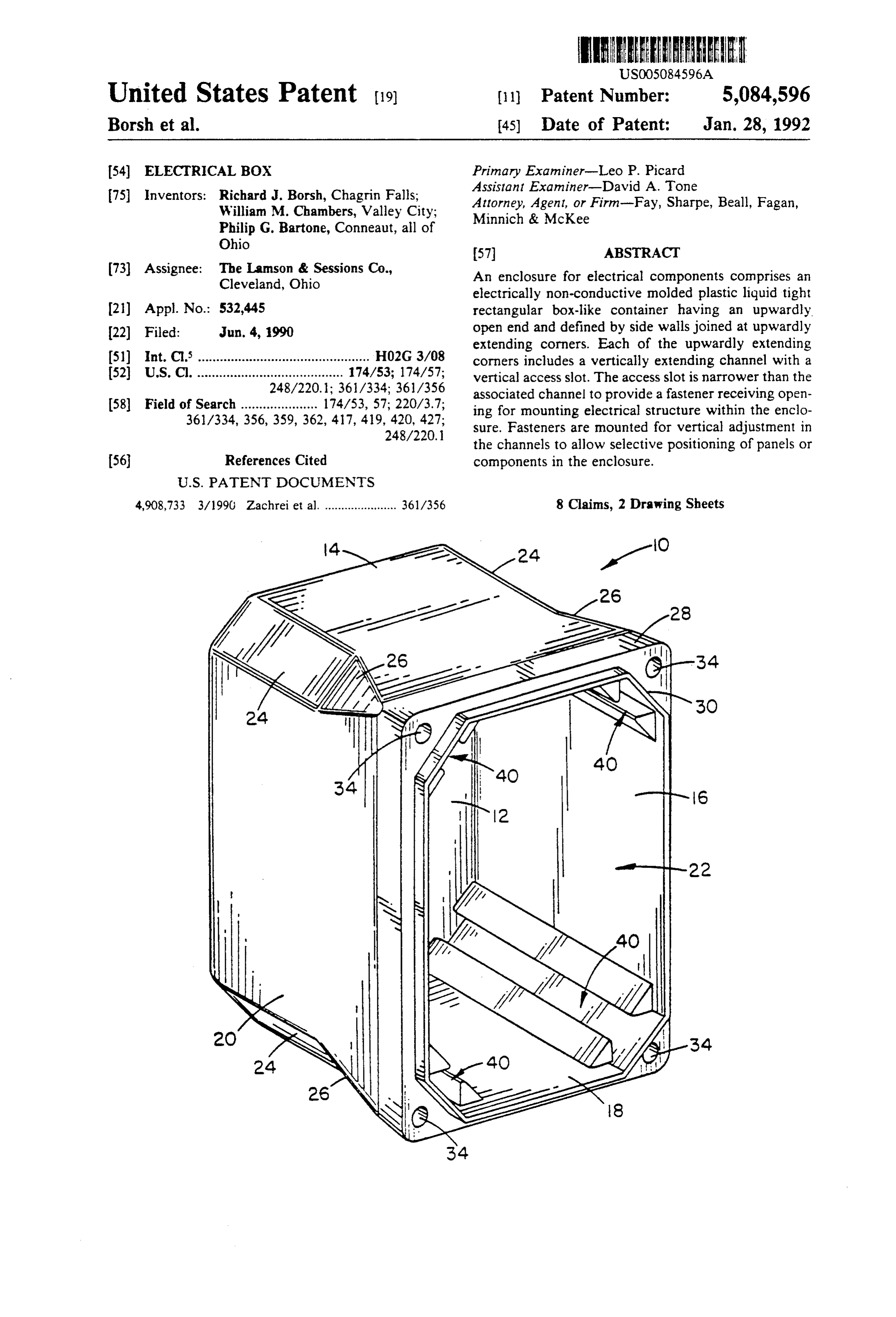
United States Patent (19) (11) Patent Number: 5,084,596 Borsh et al. 45) Date of Patent: Jan. 28, 1992 54) ELECTRICAL BOX Primary Examiner-Leo P. Picard Assistant Examiner-David A. Tone 75 Inventors: Richard J. Borsh, Chagrin Falls; Attorney, Agent, or Firm-Fay, Sharpe, Beall, Fagan, William M. Chambers, Valley City; Minnich & McKee
Philip G. Bartone, Conneaut, all of
Ohio
73 Assignee: The Lamson & Sessions Co., An enclosure for electrical components comprises an Cleveland, Ohio electrically non-conductive molded plastic liquid tight (2) Appl. No.: 532,445 rectangular box-like container having an upwardly. 22 Filed: Jun. 4, 1990 open end and defined by side walls joined at upwardly extending corners. Each of the upwardly extending 51) Int. C. ............................................... HO2G 3/08 corners includes a vertically extending channel with a 52 U.S.C. ........................................ 174/53; 174/57; vertical access slot. The access slot is narrower than the 248/220.1; 361/334; 361/356 associated channel to provide a fastener receiving open 58 Field of Search ..................... 174/53, 57; 220/3.7; ing for mounting electrical structure within the enclo 361/334,356, 359, 362, 417, 419, 420, 427; sure. Fasteners are mounted for vertical adjustment in
the channels to allow selective positioning of panels or (56) References Cited components in the enclosure.
4,908,733 3/1990 Zachrei et al. ...................... 361/356 8 Claims, 2 Drawing Sheets
Page 2
Drawing sheet — no readable text.
Page 3
Drawing sheet — no readable text.
Page 4
mounted within the box-like structure and rigidly se
ELECTRICAL BOX cured from each corner of the molded plastic enclosure. Accordingly, a primary object of the invention is the
BACKGROUND OF THE INVENTION provision of a molded plastic enclosure structure which The subject invention is directed toward the art of 5 can be used for housing and supporting a variety of enclosures and, more particularly, to an enclosure for different electrical structures without the necessity of electrical and electronic components and associated providing a different interior design. wiring and circuitry. A still further object of the invention is the provision In the electrical arts, it is often necessary to provide O of a general purpose enclosure or box which can be housings and boxes for many different components and readily adapted for housing many different electrical their associated wiring and control circuitry. Typically, components and structures the components must be fastened in place and often A still further object of the invention is the provision several different components must be mounted in the of an enclosure or box structure of the general type same housing in rigid and/or spaced relationship. described wherein the corners of the box are provided In a great many instances, the total production run of with the vertically extending clamp or fastener receiv any one particular combination of components is some ing slots which allow selective mounting and position what limited and the cost of producing a custom hous ing of associate electrical structures within the box. ing is not economically justified. In such instances, A still further object is the provision of a structure of housings having an ability to be adapted to different the general type described which is extremely rigid and
component mounting arrangements are used. Similarly, simple to use.
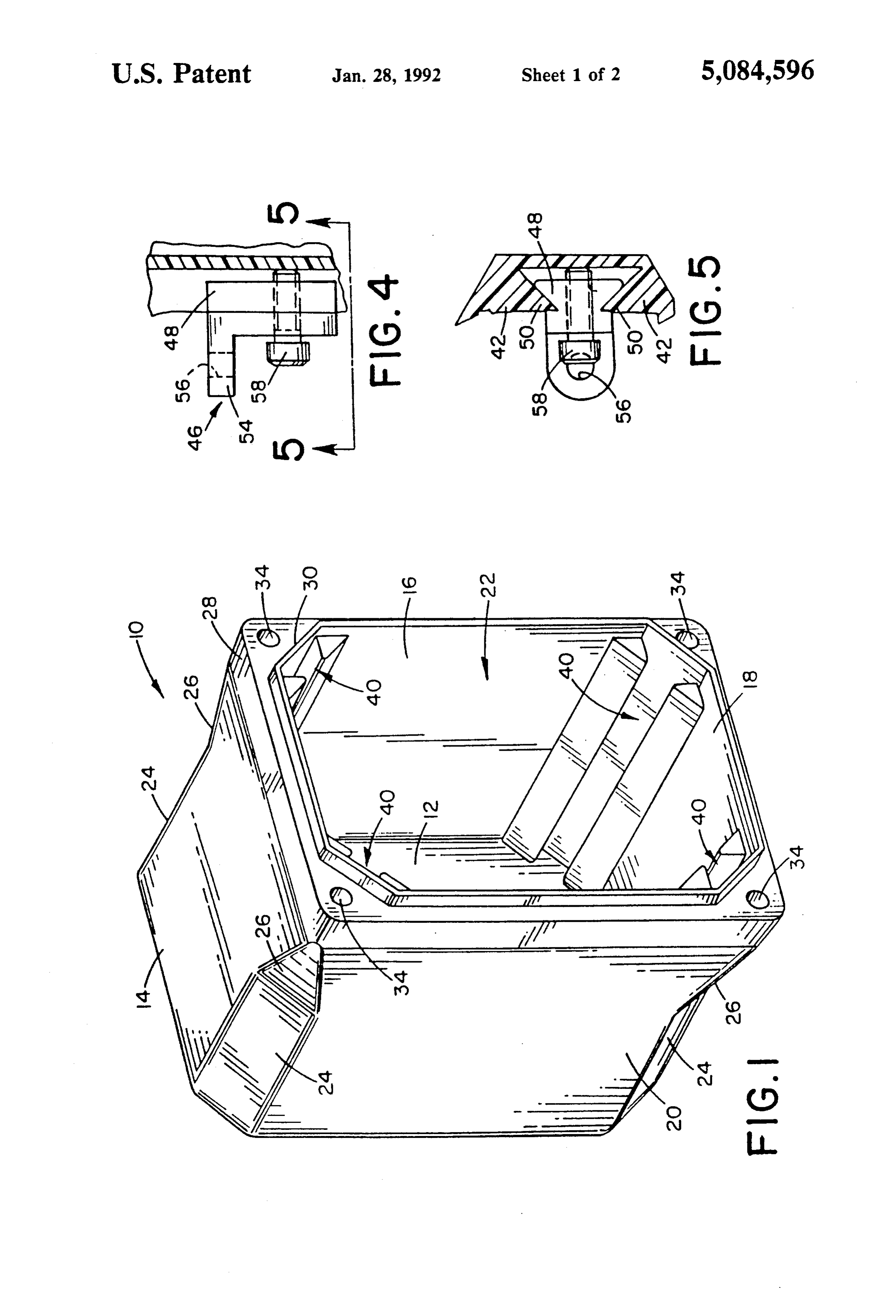
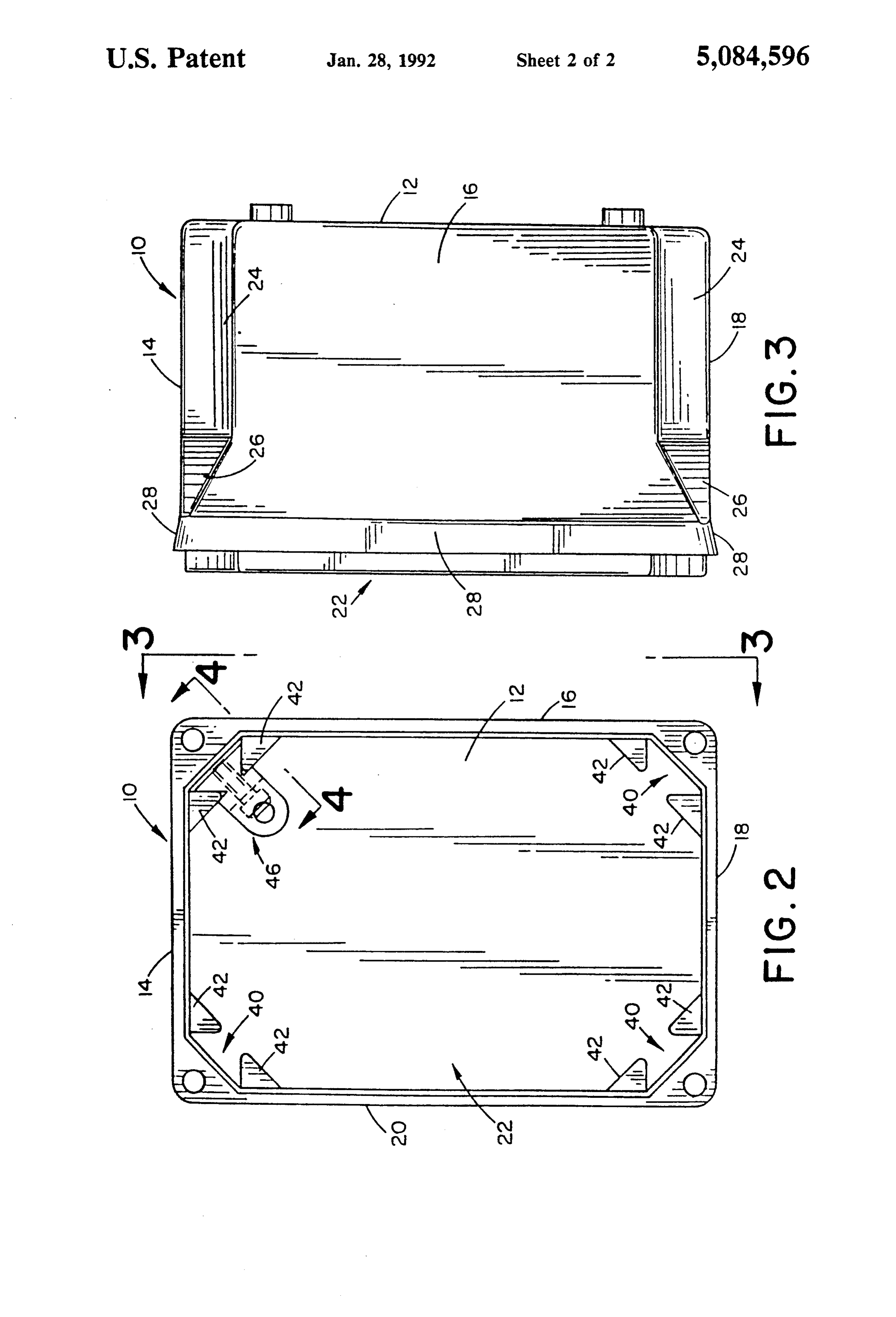
when performing field installation of various electrical BRIEF DESCRIPTION OF THE DRAWINGS wiring and control systems, it is often necessary to in stall many different combinations of components. In The above and other objects and advantages will order to maintain the number of different housings and 25 become apparent from the following description when enclosures required to a reasonable level, it is desirable read in conjunction with the accompanying drawings to have enclosures which are extremely flexible. wherein:
The subject invention is directed to a housing or FIG. 1 is a pictorial view of the molded plastic enclo enclosure structure which satisfies the above-discussed sure or housing formed in accordance with the subject needs in a simple and economical manner.
30 invention;
SUMMARY OF THE INVENTION FIG. 2 is a plan view looking into the interior of the In particular, the subject invention provides an enclo enclosure shown in FIG. 1;
FIG. 3 is a side elevational view taken on line 3-3 of sure for electrical components which is an electrically FIG. 2;
nonconductive molded plastic unitary structure having a rectangular bottom wall and four upwardly extending 35 or FIG.
support 4 is a side elevational view of a fastener clamp bracket useful in the enclosure of FIG. 1 (the side walls integral therewith. The side walls are joined to the bottom wall to form a liquid tight rectangular view is taken on line 4-4 of FIG. 2); and FIG. 5 is a view taken on line 5-5 of FIG. 4.
box-like container having an upwardly open end and four upwardly extending corners at the junctures of the DETAILED DESCRIPTION OF THE side walls. Each of the upwardly extending corners PREFERRED EMBODIMENT includes a separate pair of rib members associated there Referring more particularly to the drawings wherein with and extending from the bottom wall to the open end. The respective ribs of each pair of ribs are located the showings are for the purpose of illustrating a pre on opposite sides of the associated corner with each rib ferred embodiment of the invention only, and not for having a terminal end which is generally parallel to the 45 the purpose of limiting same, FIGS. 1 through 3 show associated corner and extends toward and terminates the overall arrangement, construction and design, of a parallel to the terminal end of the associated rib to de molded plastic enclosure or housing structure 10 which fine a vertically extending channel with a vertical ac generally comprises a rectangular botton wall 12 and cess slot. The access slot is narrower than the associated four side walls 14, 16, 18, and 20 which are integral with channel to provide a fastener receiving means for allow 50 the bottom wall and extend generally perpendicular ing electrical components and associated structure to be thereto. The bottom wall 12 and the integral side walls mounted within the enclosure through the use of the 14, 16, 18, and 20 cooperate to define a box-like, liquid vertically extending slots. tight container having an open end 22. Referring in Preferably, and in accordance with a more limited particular to FIGS. 1 and 3, it will be noted that the aspect of the invention, the ribs are molded integrally 55 corners of the enclosure 10 are defined by flat sections with the side walls and have a tapered cross-section in 24 which extend diagonally between the adjacent side planes parallel to the bottom wall. The tapered cross walls. At their upper end, the corners include a transi section is arranged so that the slot can receive a corre tion surface 26. Additionally, an outwardly flared sec spondingly shaped support bracket which can be suit tion 28 (see FIG. 3) extends completely about the open ably clamped within the slot. end of the enclosure. The combination of the surfaces In accordance with a further aspect of the invention, 24, 26, and 28 function to deflect water runoff away each pair of ribs is generally parallel to every other pair from the open end of the enclosure. This assists in keep of ribs and adjustable connecting means are releasably ing water and other liquids away from any covers or the clamped to the ribs. like applied to the open end or side of the container. Preferably, each corner of the rectangular box-like 65 With respect to the use of covers or lids, the subject structure includes a pair of the ribs positioned to define embodiment preferably includes a relatively narrow a separate vertically extending channel in each corner. outwardly extending wall or flange-like portion 30 Thus, interior panels, dividing walls, and the like, can be which encircles the open end 22. This provides a sealing
Page 5
lip or rim for engagement with gaskets or the like suit any of the vertically extending recesses 40. For exam ably carried in any connecting lid or cover structure ple, brackets 46 could be provided in each of the corner (not shown). To facilitate mounting or connection of recesses 40 and all located at the same relative elevation covers, lids, or the like, the upper ends of the corners for connecting a plate or the like in position in the box. are provided with suitable fastener receiving openings Alternatively, the brackets can be positioned at sepa 34 as shown. The openings 34 can be unthreaded for use rately determined elevations to hold the supported with self-tapping screws. Alternately, they can be components in desired positions of adjustment. tapped to provide internal threads or molded with metal The invention has been described with reference to thread defining inserts therein. The particular arrange the preferred embodiment. Obviously, modifications ment of the corners and their fastener receiving open O and alterations will occur to others upon a reading and ings form no part of the present invention. understanding of this specification. It is intended to As previously discussed, such enclosure boxes are include all such modifications and alterations insofar as used for housing electrical components and control they come within the scope of the appended claims or circuits and should preferably be capable of readily the equivalents thereof.
being adapted to a variety of different electrical struc 5 What is claimed is:
tures and usages. In the subject embodiment, means are 1. An enclosure for electrical components and the provided for allowing ready installation of dividing like, comprising:
panels, support panels, and the like. Additionally, the an electrically non-conductive molded plastic unitary design is such that individual electrical components, structure having a rectangular bottom wall and control elements, and similar structures can be mounted four upwardly extending side walls integral there rigidly and at different levels within the enclosure. For with and joined to form a liquid tight rectangular this purpose, the subject device is provided with verti box-like container having an upwardly open end cally extending mounting slots positioned in the corners and four upwardly extending corners at the junc of the enclosure. As will become apparent, any particu tures of said side walls; lar number of the fastener receiving slots or recesses 25 each of said upwardly extending corners including a could be provided in various locations. However, in the separate pair of rib members associated there with subject embodiment, one recess is provided in each of and molded integrally with said walls and extend the four corners. Specifically, as best shown in FIGS. 1 ing from said bottom wall to said open end, the and 2, a separate longitudinally extending fastener re respective ribs of each said pair of ribs being lo ceiving recess 40 is formed in each of the individual 30 cated on opposite sides of the associated corner corners. As best shown in FIG. , each recess prefera with each rib having a tapered cross-section in bly extends from the bottom wall 12 to the open end 22. planes parallel to the bottom wall and having a Moreover, each of the recesses 40 is defined by a pair of terminal end which is generally parallel to the rib members 42 which are formed integrally with the associated corner and extends toward and termi side walls. In particular, as best illustrated in FIG. 2, 35 nates parallel to the terminal end of the associated each of the ribs 42 extend outwardly from an associated rib to define a vertically extending channel with a side wall and have a generally tapered cross-section as vertical access slot, said access slot being narrower shown. The outer free ends of the ribs extend toward than the associated channel to provide a fastener one another and are spaced apart so that each channel receiving means for mounting electrical structure or recess 40 opens to the interior box through a signifi within said enclosure, cantly narrower vertical access slot. This access slot 2. The enclosure as defined in claim 1 wherein the allows and facilitates connection of suitable mounting ribs in each pair have planar surfaces facing the interior brackets, fasteners, and the like. of the enclosure which extend from the bottom to the The preferred form of connector and mounting open end and lie in the same plane.
bracket is illustrated in FIGS. 2, 4, and 5. Specifically, 45 3. An enclosure as defined in claim 1 wherein each each of the recesses 40 has a trapezoidal shape with the pair of ribs is generally parallel to every other pair of narrower side of the trapezoid defining the access slot. ribs.
Adapted to be mounted in the recess 40 is a mounting 4. An enclosure as defined in claim 3 wherein said ribs connector or bracket assembly as shown in FIGS. 4 and each have a relatively thick base and taper to a rela 5. The bracket assembly 46 includes a first body section SO tively thin terminal end.
48 which has a cross-sectional shape corresponding to 5. An enclosure as defined in claim 3 wherein said ribs the recess 40 (see FIGS. 2 and 5). Body section 48 is are integral with the side walls.
sized so as to be slidably received within the recess 40. 6. An enclosure as defined in claim 1 including a An outer section of the bracket member 46 connects to support wall spaced from said botton wall, said support the body section 48 and in combination therewith forms 55 wall being supported by adjustable connecting means V-shaped grooves or slots 50 which, as shown in FIG. extending from said support wall into at least one of the 5, receive the free ends of the ribs 42. The sizing of the vertically extending channels. recesses is such as to allow the bracket to be freely 7. An enclosure as defined in claim 6 wherein said slidable in a vertical direction on the ribs 42. Connected adjustable connecting means are releasably clamped to to the body and extending laterally therefrom is a the ribs which define the at least one vertically extend mounting plate or connecting portion 54 which prefera ing channel.
bly has a screw receiving opening 56 formed therein as 8. An enclosure for electrical components and the shown. A threaded bolt member 58 extends inwardly like, comprising:
through a suitable threaded opening in body section 48. an electrically non-conductive molded plastic unitary The screw 58 provides means for clamping the bracket 65 structure having a rectangular bottom wall and 46 in a desired position of adjustment in the recess 40. four upwardly extending side walls integral there As can be readily seen from FIG. 2, any number of the with and joined to form a liquid tight rectangular mounting brackets 46 could be selectively mounted in box-like container having an upwardly open end
Page 6
and four upwardly extending corners at the junc terminal end which is generally parallel to the tures of said side walls; associated corner and extends toward and termi each of said upwardly extending corners including a nates parallel to the terminal end of the associated separate pair of rib members associated therewith rib to define a vertically extending channel with a and extending from said bottom wall to said open 5 vertical access clot, said access slot being narrower end, each pair of ribs being generally parallel to every other pair of ribs and the respective ribs of than the associated channel to provide a fastener each said pair of ribs being located on opposite receiving means for mounting electrical structure sides of the associated corner with each rib having within said enclosure.
a relatively thick base tapering to a relatively thin 10 k k
Provenance
- Collection
- Cited prior art
- Original PDF
- patentimages.storage.googleapis.com →
- Filed
- 1990-06-04
- Pages
- 6
- Method
- pdftotext (the PDF's own text layer) + pdftoppm 300dpi page scans
- Source
- Google Patents bibliographic record
- Granted
- 1992-01-28
- Inventors
- Richard J. Borsh; William M. Chambers; Philip G. Bartone; Lamson and Sessions Co
- Transcribed from
- patentimages.storage.googleapis.com →