patent · US4766884
Accumulator arrangement for the sunlight energy
30 August 1988
Page 1 — bibliographic record
United States Patent (19) 11 Patent Number: 4,766,884 Mori (45. Date of Patent: Aug. 30, 1988 (54 ACCUMULATOR ARRANGEMENT FOR 4,424,805 l/1984 Neary .................................. 126/417 THE SUNLIGHT ENERGY 4,483,311 11/1984 Whitaker ...........
4,493,940 l/1985 Takaoka .............................. 126/450 76 Inventor: Kei Mori, No. 3-16-3-501, Kaminoge,
Setagaya-ku, Tokyo, Japan FOREIGN PATENT DOCUMENTS 21 Appl. No.: 58,880 2373018 8/1978 France ................................ 126/440 0014031 2/1979 Japan ................................... 126/440 (22 Filed: Jun. 5, 1987 0046341 4/1980 Japan ................................... 126/440 0091151 7/1981 Japan ................................... 126/440
Related U.S. Application Data 0155346 12/1981 Japan ..... ... 126/440 0084948 5/1982 Japan ..... ... 126/440 62 Division of Ser. No. 548,427, Nov. 3, 1983. 0092754 6/1983 Japan ..... ow 126/440 (30) Foreign Application Priority Data 0.123056 7/1983 Japan ..... was psala e s - 126/440 0.142151 8/1983 Japan ................................... 126/440
Nov. 10, 1982 JP Japan ................................ 57-197135 0.066052 4/1985 Japan ................................... 126/440 Nov. 15, 1982 JP Japan ................................ 57-200229 Primary Examiner-Randall L. Green 51) Int. Cl.' ............................. F24J 2/40, F24J 2/08 Attorney, Agent, or Firn-Wegner & Bretschneider 52 U.S. C. .................................... 126/419; 126/440; 57 ABSTRACT
58 Field of Search ............... 126/417, 440, 428,432, A solar energy accumulator arrangement including a 126/444, 900, 419; 350/96.1 plurality of optical systems for focusing the sunlight and (56) References Cited a fluid passage in a transparent body which is disposed such that it passes through, or in the vicinity of, the
4,004,571 1/1977 Schwerzel et al. ................. 126/47 substance which induces a photochemical reaction by 4,055,948 11/1977 Kraw et al....... ... 126/417 light energy and accumulates the energy.
4,395,582 7/1983 Damther ...... ... 126/417 4,411,490 10/1983 Daniel ................................. 126/440 6 Claims, 3 Drawing Sheets
Page 2
Drawing sheet — no readable text.
Page 3
Drawing sheet — no readable text.
Page 4
Drawing sheet — no readable text.
Page 5
of the photoconductor disposed at a certain position,
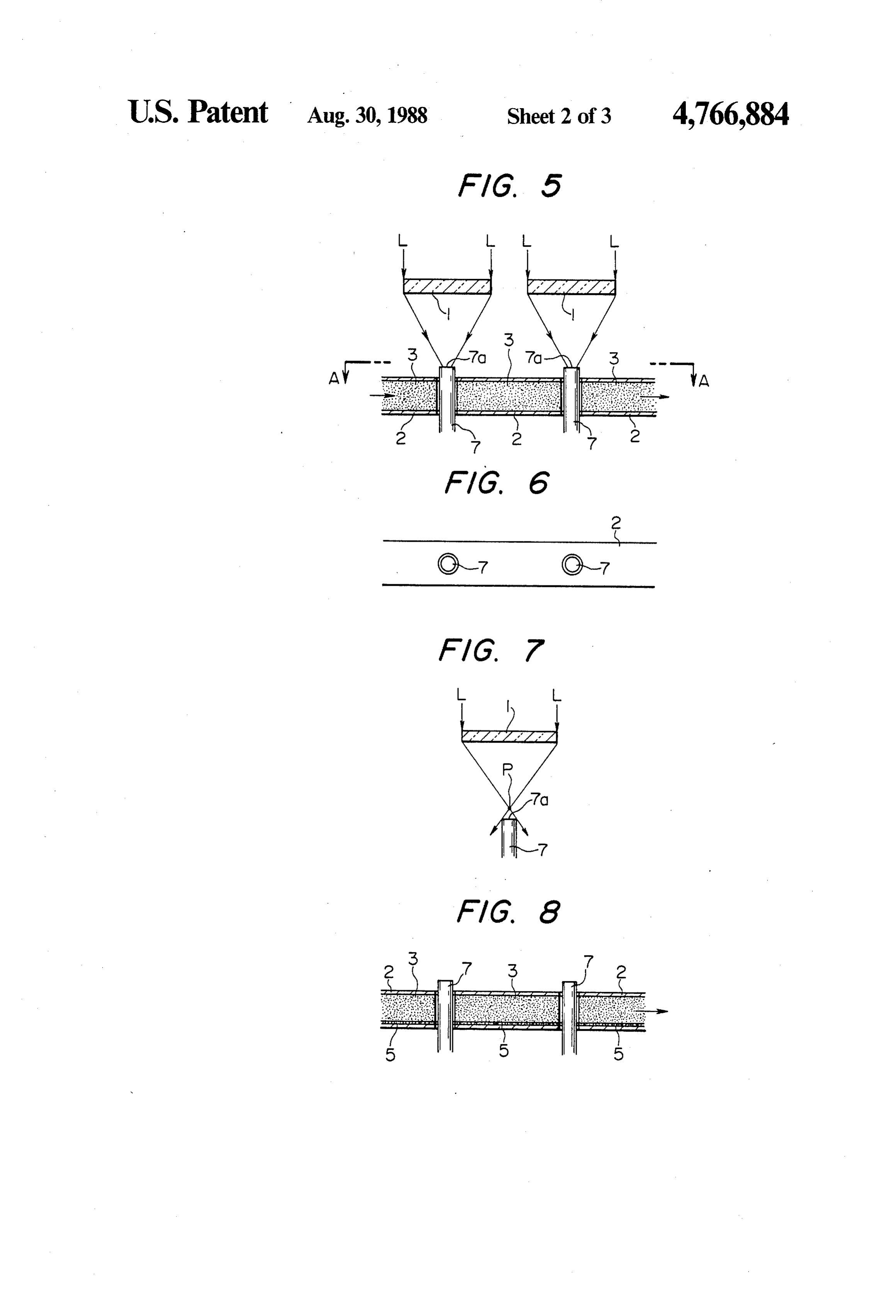
ACCUMULATOR ARRANGEMENT FOR THE FIGS. 8 to 11 being sectional views illustrative of the SUNLIGHT ENERGY embodiment of the present invention, and FIG. 12 being a plan view of FIG. 11.
This application is a divisional of Ser. No. 548,427, DETAILED EXPLANATION OF THE
FIELD OF THE INVENTION
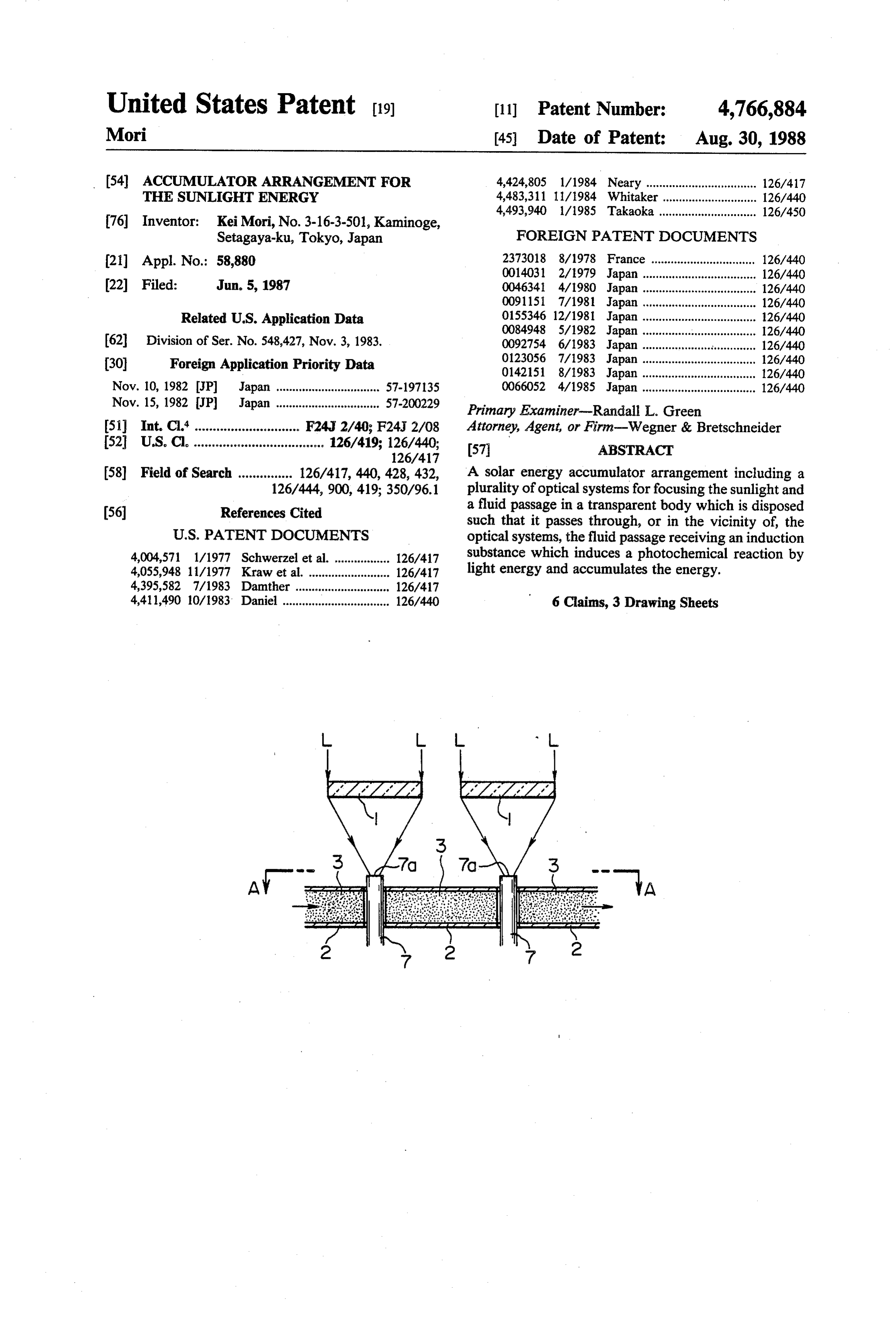
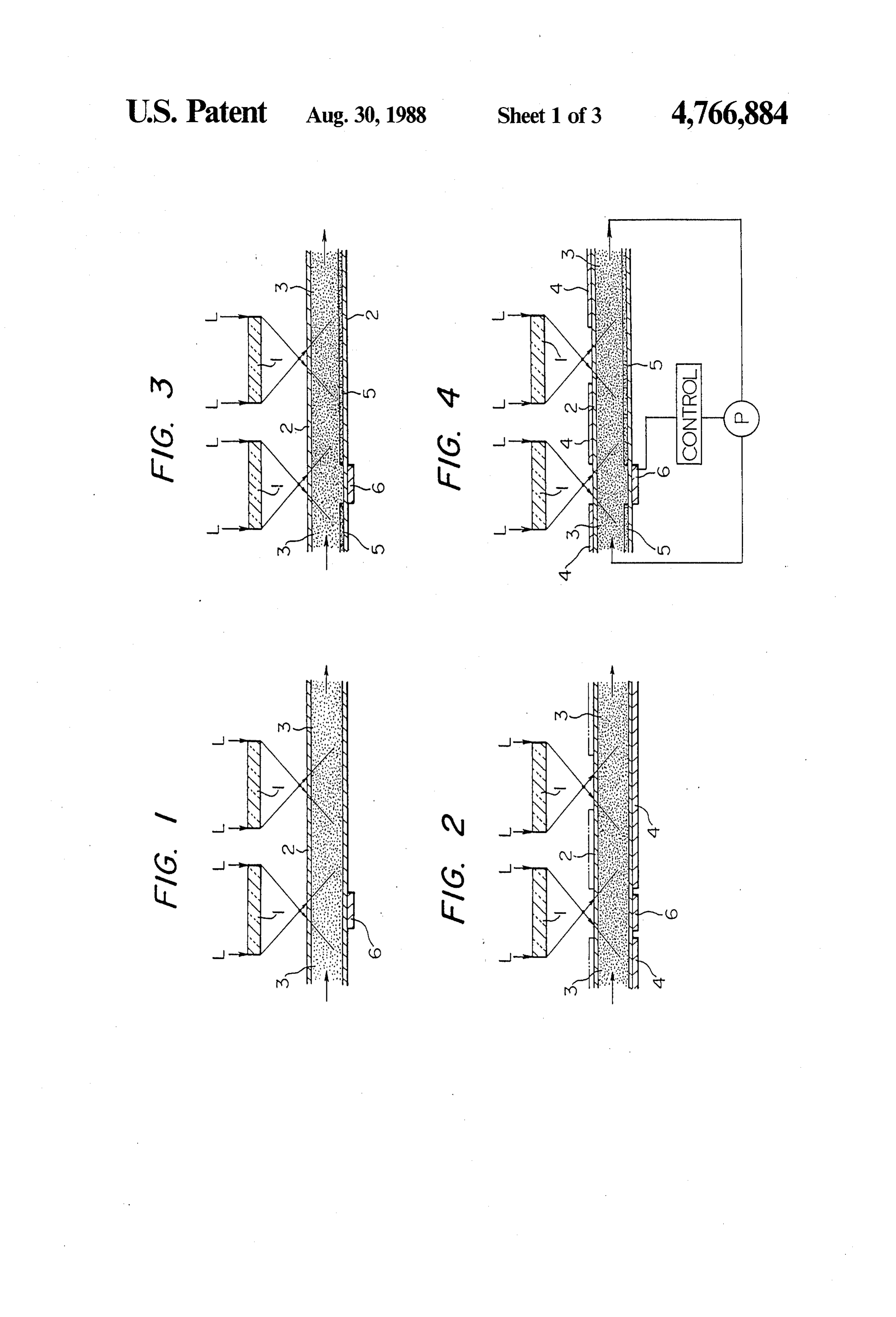
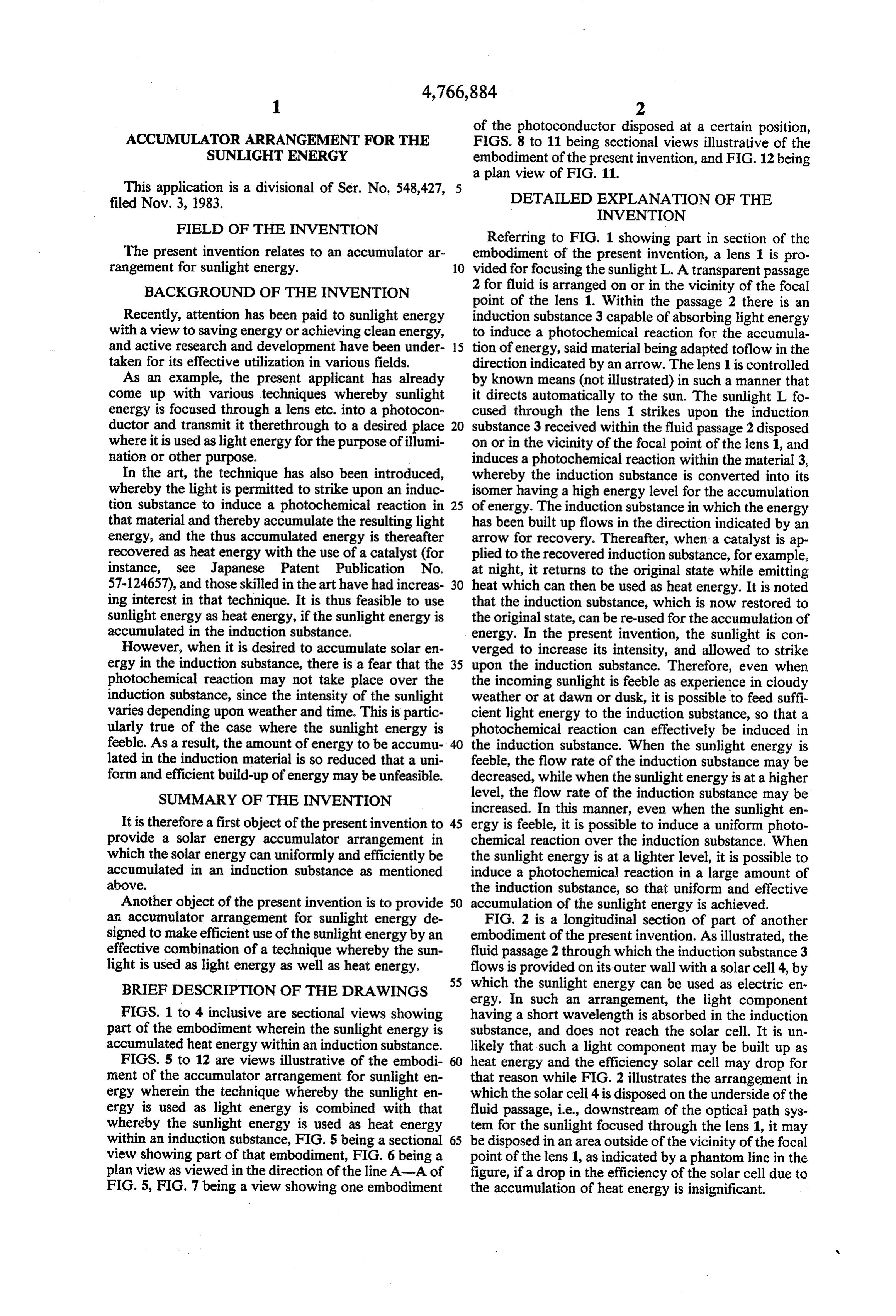
Referring to FIG. 1 showing part in section of the
The present invention relates to an accumulator ar embodiment of the present invention, a lens 1 is pro rangement for sunlight energy. 10 vided for focusing the sunlight L. A transparent passage BACKGROUND OF THE INVENTION 2 for fluid is arranged on or in the vicinity of the focal point of the lens 1. Within the passage 2 there is an
Recently, attention has been paid to sunlight energy induction substance 3 capable of absorbing light energy with a view to saving energy or achieving clean energy, to induce a photochemical reaction for the accumula and active research and development have been under 15 tion of energy, said material being adapted toflow in the taken for its effective utilization in various fields. direction indicated by an arrow. The lens 1 is controlled As an example, the present applicant has already by known means (not illustrated) in such a manner that come up with various techniques whereby sunlight it directs automatically to the sun. The sunlight L fo energy is focused through a lens etc. into a photocon cused through the lens 1 strikes upon the induction ductor and transmit it therethrough to a desired place 20 substance 3 received within the fluid passage 2 disposed where it is used as lightenergy for the purpose of illumi on or in the vicinity of the focal point of the lens 1, and nation or other purpose. induces a photochemical reaction within the material 3, In the art, the technique has also been introduced, whereby the induction substance is converted into its whereby the light is permitted to strike upon an induc isomer having a high energy level for the accumulation tion substance to induce a photochemical reaction in 25 of energy. The induction substance in which the energy that material and thereby accumulate the resulting light has been built up flows in the direction indicated by an energy, and the thus accumulated energy is thereafter arrow for recovery. Thereafter, when a catalyst is ap recovered as heat energy with the use of a catalyst (for plied to the recovered induction substance, for example, instance, see Japanese Patent Publication No. at night, it returns to the original state while emitting 57-124657), and those skilled in the art have had increas 30 heat which can then be used as heat energy. It is noted ing interest in that technique. It is thus feasible to use that the induction substance, which is now restored to sunlight energy as heat energy, if the sunlight energy is the original state, can be re-used for the accumulation of accumulated in the induction substance. energy. In the present invention, the sunlight is con However, when it is desired to accumulate solar en verged to increase its intensity, and allowed to strike ergy in the induction substance, there is a fear that the 35 upon the induction substance. Therefore, even when photochemical reaction may not take place over the the incoming sunlight is feeble as experience in cloudy induction substance, since the intensity of the sunlight weather or at dawn or dusk, it is possible to feed suffi varies depending upon weather and time. This is partic cient light energy to the induction substance, so that a ularly true of the case where the sunlight energy is photochemical reaction can effectively be induced in feeble. As a result, the amount of energy to be accumu the induction substance. When the sunlight energy is lated in the induction material is so reduced that a uni feeble, the flow rate of the induction substance may be form and efficient build-up of energy may be unfeasible. decreased, while when the sunlight energy is at a higher SUMMARY OF THE INVENTION level, the flow rate of the induction substance may be increased. In this manner, even when the sunlight en
It is therefore a first object of the present invention to 45 ergy is feeble, it is possible to induce a uniform photo provide a solar energy accumulator arrangement in chemical reaction over the induction substance. When which the solar energy can uniformly and efficiently be the sunlight energy is at a lighter level, it is possible to accumulated in an induction substance as mentioned induce a photochemical reaction in a large amount of above. the induction substance, so that uniform and effective Another object of the present invention is to provide 50 accumulation of the sunlight energy is achieved. an accumulator arrangement for sunlight energy de FIG. 2 is a longitudinal section of part of another signed to make efficient use of the sunlight energy by an embodiment of the present invention. As illustrated, the effective combination of a technique whereby the sun fluid passage 2 through which the induction substance 3 light is used as light energy as well as heat energy. flows is provided on its outer wall with a solar cell 4, by 55 which the sunlight energy can be used as electric en
BRIEF DESCRIPTION OF THE DRAWINGS ergy. In such an arrangement, the light component FIGS. 1 to 4 inclusive are sectional views showing having a short wavelength is absorbed in the induction part of the embodiment wherein the sunlight energy is substance, and does not reach the solar cell. It is un accumulated heat energy within an induction substance. likely that such a light component may be built up as FIGS. 5 to 12 are views illustrative of the embodi heat energy and the efficiency solar cell may drop for ment of the accumulator arrangement for sunlight en that reason while FIG. 2 illustrates the arrangement in ergy wherein the technique whereby the sunlight en which the solar cell 4 is disposed on the underside of the ergy is used as light energy is combined with that fluid passage, i.e., downstream of the optical path sys whereby the sunlight energy is used as heat energy tem for the sunlight focused through the lens 1, it may within an induction substance, FIG. 5 being a sectional 65 be disposed in an area outside of the vicinity of the focal view showing part of that embodiment, FIG. 6 being a point of the lens 1, as indicated by a phantom line in the plan view as viewed in the direction of the line A-A of figure, if a drop in the efficiency of the solar cell due to FIG. 5, FIG. 7 being a view showing one embodiment the accumulation of heat energy is insignificant.
Page 6
FIG. 3 is a longitudinal section of part of a further direction indicated by an arrow. In this embodiment, embodiment of the present invention. As illustrated, the the lens 1 is controlled such that it directs automatically fluid passage 2 through the induction substance flows is to the sun by means of a suitable device (not shown). provided on its inner wall with a black body 5. In this The sunlight L focused through the lens 1 is introduced arrangement, the heat energy of the sun entering the into the photoconductor 7 having its light receiving end fluid passage 2 is effectively transmitted to the induction 7a located at the focal point of the lens 1, through substance 3 to increase its temperature. Thus, when the which it is transmitted to any desired place for the il induction substance is recovered, the heat energy car lumination or other purpose. A part of the sunlight ried by the induction substance can be used. which is not admitted into the photoconductor 7 strikes FIG. 4 is a longitudinal section of part of a still fur 10 upon the induction substance 3 flowing through trans ther embodiment of the present invention. As illus parent fluid passage 2, giving rise to a photochemical trated, the fluid passage is provided on its outer wall reaction which converts the induction substance into its with the solar cell 4 and on its inner wall with the black isomer for the accumulation of the energy. The induc body 5, whereby the sunlight energy can be used as tion substance which accumulates the energy flows in either heat energy or electric energy. 15 the direction indicated by an arrow for recovery. While the present invention has been described with Thereafter, when a catalyst is applied, for instance, at reference to several embodiments, the present invention night, it returns to its original state while giving off heat is not limited thereto. For instance, when the present which can then be used as heat energy. invention is applied within the atmosphere containing The induction substance which is now restored to the less ultraviolet rays, a sensitizer may be added to the 20 original state can be reused in the foregoing manner for induction substance, which converts the light compo the accumulation of energy. As mentioned above, the nent having a wavelength of less than about 360 mm present invention makes it possible to introduce the into the light component having a wavelength of about sunlight focussed through a lens or the like into a photo 500 mm, whereby a photochemical reaction can more conductor, through which it is transmitted to any de effectively be induced in the induction substance. When 25 sired place for the illumination or other purpose. In the flow rate of the induction substance is controlled addition, a part of the sunlight which is not used for depending upon the intensity of the sunlight, a light illumination can effectively be used to accumulate the detecting cell 6 is disposed on a line extending from the energy in the induction substance, which is thereafter focus of the lens 1 and on the outer surface of the under used as heatenergy. According to the present invention side of the fluid passage 2, as shown in FIGS. 1 to 4. The 30 the sunlight can effectively used. If the light receiving flow rate of the induction substance is controlled by the end 7a of the photoconductor 7 is located in the rear of output signal of the cell 6, so that the light acting upon the focal point P of ultraviolet rays, as illustrated in the induction substance is directly detected, thereby FIG. 7, the visible light is admitted into the photocon more effectively controlling the flow rate of the induc ductor 7 without introducing thereinto the light compo tion substance. 35 nent having a short wavelength, such as ultraviolet The embodiments in which the sunlight energy is rays, and reaches the rear induction substance. In this accumulated in the induction substance have been de manner, the sunlight can more effectively be used. It is scribed. In what follows, explanation will be made to noted that the induction substance reacts photochemi several embodiments wherein the aforesaid accumula cally with the light component having a wavelength of tor arrangement for the sunlight energy is effectively no more than about 400 nm.
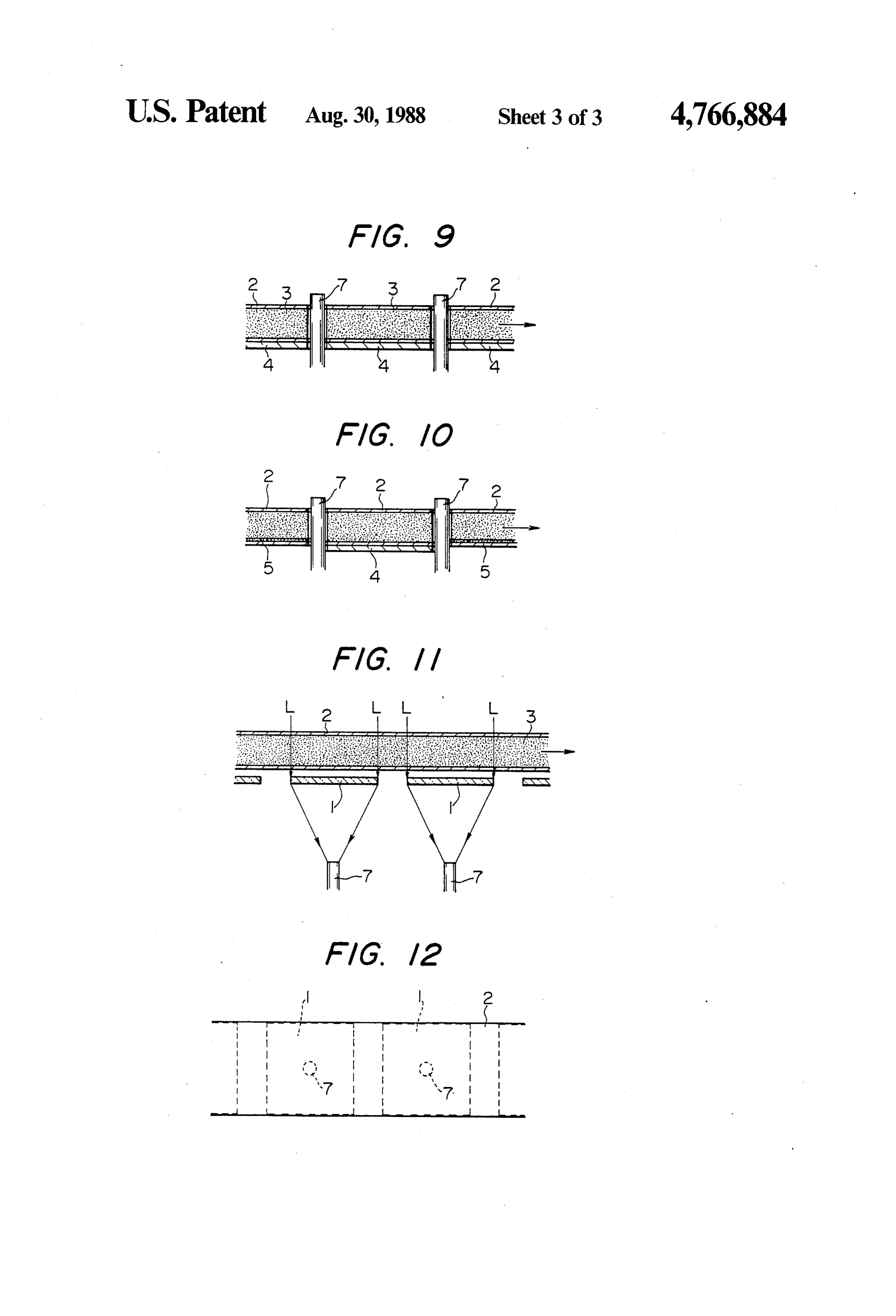
combined with the sunlight collector arrangement al FIG. 8 is a longitudinal section showing part of a still ready proposed by the present applicant. further embodiment of the present invention. In this To make the most effective use of sunlight energy, it embodiment, the fluid passage 2 formed of a transparent has to be applied as light energy without converting it body, through which the induction substance 3 flows, is into another form of energy such as light or electric 45 provided on its inner wall with the black body 5 as energy. From this point-of-view, the present applicant illustrated, by which the sunlight energy entering the has made various proposals about sunlight collectors in fluid passage 2 is effectively transmitted to the induction which the sunlight energy is focused through a lens or substance 3 to increase its temperature. In the recovery the like into a photoconductor, through which it is of the induction substance, the heat energy carried by transmitted to a place where illumination is needed. In 50 said induction substance can be used. the following embodiments, the sunlight collector as FIG. 9 is a longitudinal section showing part of a still mentioned above is effectively incorporated into the further embodiment of the present invention, As illus aforesaid arrangement for the conversion of the sun trated, the fluid passage 2 formed of a transparent body, light energy into heat energy, whereby the light and through which the induction substance 3 flows, is pro heat energies of the sunlight can simultaneously be uti 55 vided on its underside with the solar cell 4, upon which lized in a single unit. the light transmitted through the induction substance 3 FIG. 5 is a longitudinal section illustrating part of a acts effectively. According to this embodiment, the still further embodiment of the present invention, and sunlight can also be used as electric energy. With such FIG. 6 a view as viewed from the direction of the line an arrangement, the light component having a short A-A of FIG. 5. In these figures, 1 is a lens for focusing wavelength is absorbed without reaching the solar cell. the sunlight L, 7, a photoconductor having its light It is thus unlikely that such a light component may be receiving end 7a disposed in the vicinity of the focal accumulated as heat energy in the solar cell, and the position of the lens 1, and 2 a fluid passage formed of a efficiency of the solar cell may drop for that reason. As transparent body and disposed in the rear of the light will easily be appreciated from FIG. 10, the black body receiving end 7a of the photoconductor 7. Within the 65 5 of FIG. 8 may be used in combination with the solar fluid passage 2, there is an induction substance 3 to cell 4 of FIG. 9.
absorb light energy, cause a photochemical reaction and While the present invention has been described with accumulate the energy, which flows, for instance, in the reference to its specific embodiments, it is not limited

Page 7
thereto. For instance, if the flow rate of the induction 1. A solar energy accumulator arrangement compris substance is controlled in response to a detection signal ing an optical system for focussing the sunlight and a resulting from the detection of the intensity of the sun photoconductor having its light receiving end disposed light, the energy is then more effectively accumulated at the focal point of said optical system, said sunlight in the induction substance. When the present invention being focussed through said optical system and trans is applied within the atmosphere containing less ultravi mitted through said photoconductor to any desired olet rays, a sensitizer may be mixed with the induction place, and further including a transparent conduit defin substance. The light component having a wavelength of ing a fluid passage through which said photoconductor no more than about 360 nm is converted by said sensi passes, an induction substance flowing through said tizer into a light component having a wavelength of O fluid passage at a flow rate responsive to the intensity of about 500 nm, with the result that a photochemical said sunlight, said induction substance being capable of reaction is more effectively induced in the induction transformation to a higher energy level by a photo substance. chemical reaction to thereby accumulate solar energy FIG. 11 is a longitudinal section showing part of a from the light component thereof, whereby, when the still further embodiment of the present invention, and 15 energy level of said induction substance returns to its FIG. 12 is a plan view of FIG. 11. This embodiment is original state, said energy is emitted as heat. effectively applied to sunlight in outer space which 2. The arrangement as recited in claim 1, in which a contains large amounts of X-rays, shortwave ultraviolet solar cell is disposed on the outer surface of said fluid rays such as vacuum ultraviolet rays and medium or passage downstream of the optical path of said optical long wave ultraviolet rays. The sensitizer required in 20 system.
the foregoing embodiments is dispensed with, since the 3. The arrangement as recited in claim 1, in which a sensitizer may be destroyed by intensive ultraviolet black body is disposed on the inner surface of said fluid rays. The more characteristic feature of this embodi passage downstream of said optical system. ment is that intensive ultraviolet rays, etc. are absorbed 4. The arrangement as recited in claim 1, in which in the induction substance without introducing there 25 said induction substance contains a sensitizer. into light components having such a short wavelength, 5. The arrangement as recited in claim 1, in which a so that only visible light of good quality and safety is light detecting cell is disposed on the outer surface of admitted into the induction substance. Since the fluid the underside of said fluid passage, said cell producing passage 2 of a transparent body is disposed in front of an output signal in response to which the flow rate of the lens 1 in this embodiment, there is no need for the 30 said induction substance is controlled. provision of any opening for the insertion of the photo 6. The arrangement as recited in claim 1 further com conductor through the fluid passage. Hence, the fluid prising means for controlling the flow rate of said in passage of a simple structure is easily be assembled at duction substance responsive to the intensity of said low cost. sunlight.
What is claimed is: 35 sk xk is k is
Provenance
- Collection
- Cited prior art
- Original PDF
- patentimages.storage.googleapis.com →
- Filed
- 1987-06-05
- Pages
- 7
- Method
- pdftotext (the PDF's own text layer) + pdftoppm 300dpi page scans
- Source
- Google Patents bibliographic record
- Granted
- 1988-08-30
- Inventors
- Kei Mori
- Transcribed from
- patentimages.storage.googleapis.com →