patent · US1447640
Fuel mixer for explosion motors
6 March 1923
Page 1
Drawing sheet — no readable text.
Page 2
Patented Mar. 6, 1923. 1447,640
UNITED STATES PATENT OFF ECE.
WILLIs J. BERNETT, OF KANSAs CITY, MIssou RI.
FUEL VIIXER FOR EXPLOSION MOTORS.
Application filed April 22, 1920. Serial No. 375,794.
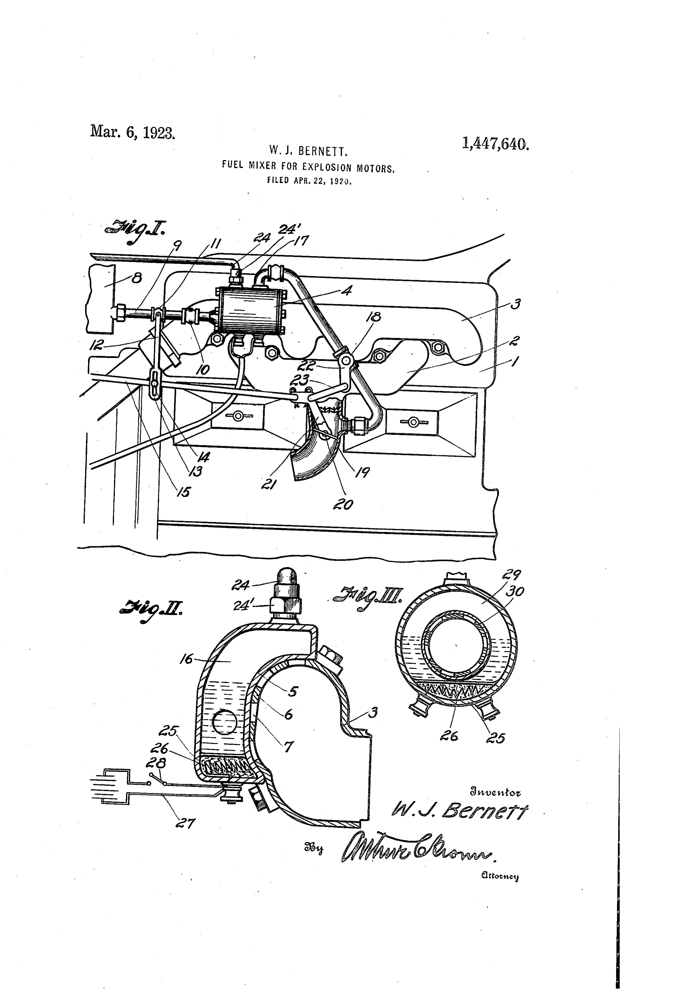
To all whom it may concern: 1 designates an engine of appropriate con Be it known that I, WILLIs J. BERNETT, a struction provided with an intake manifold citizen of the United States, residing at 2 and an exhaust manifold 3. Secured to the 60 Kansas City, in the county of Jackson and manifold 3 is a vaporizer tank or chamber 5 State of Missouri, have invented certain 4,about having a curved inner wall 5 to fit closely the wall 6 of the manifold 3. The new and useful Improvements in Fuel Mix wall 6 of the manifold 3 is provided with a .
ers for Explosion Motors; and I do declare plurality the following to be a full, clear, and exact of openings 7 whereby the exhaust description of the invention, such as will gases may contact with the curved wall 5 so 65 10 enable others skilled in the art to which it as to heat the contents of the vaporizing appertains to make and use the same, refer tank or chamber 4. The vaporizing tank or ence being had to the accompanying draw chamber 4 is supplied from a supply tank 8 , ings, and to the letters and figures of refer of appropriate construction through the me ence marked thereon, which form a part of dium of a pipe 9, which communicates with 70 15 this specification. one end of the tank or chamber 4. Within This invention relates to an air and gas or the pipe 9 is a check valve 10, opening in the vapor mixer whereby liquid fuel is adapted direction of the tank 4 and the pipe 9 is also to be vaporized or gasified and then mixed provided with a mechanically actuated valve with air, preparatory to being introduced 11, having a valve lever 12, at one end of 75 20 into the combustion cylinder of an explosion which is a slot 13 engaged by a pin or lug 14 motor as the fuel charge. on the pull rod-15, which operates certain According to my invention the fuel oil valves for determining, the proportions of may be first gasified or vaporized and then ture.
air and vapor or gas to constitute the mix mixed with a requisite amount of air to ren Leading from the upper portion of the 25 der it efficient as a fuel charge, the propor tions of vapor and air being determined by chamber or tank 4, that is, from the gas or certain measuring devices or valves em vapor space 16, is an exhaust pipe 17, having ployed outside of the combustion chamber a valve 18 and discharging into the inlet of the engine. The construction of the de pipe 19 of the intake manifold 2. The dis 30 vice is such that true carburation does not charge end of pipe 17 is above an air valve, take place but rather a mixing of the com shown as a butterfly valve 20, which may be ponent parts of the fuel charge. The liquid actuated by an elbow lever 21 connected to constituent of the fuel charge is heated to a the crank arm 22 of the valve 18 by a link temperature high enough to vaporize or 23, the elbow lever 21 being connected to the 9 O S5 gasify it and as it mixes with the air, it will pull rod 15. Therefore, when the pull rod enter the combustion chamber in a heated is operated in either direction, the valves 18 condition so that ignition may be promoted and proportions 20 are synchronously operated to vary by the compression within the cylinder and the of vapor or gas and air 95 which enters the inlet manifold 2.
the spark of the spark plug.
40 I have also provided means to be asso If the pressure in the space 16 exceeds a ciated with the generating device whereby determined amount, it may escape through the liquid constituent may be primed or pre an escape pipe 24, in which a suitable pres heated in starting the engine. sure valve 24' may be located if desired. When the parts are assembled, the liquid 00
Other novel features of the invention will will 45 be apparent by reference to the following flow from chamber 8 to chamber or description in connection with the accom tank 4 through pipe 9, the flow being de panying drawings, in which termined by the valve 11. The heat from Fig. I is a fragmentary, diagrammatic the manifold 3 will vaporize or gasify the view of an engine to which my invention is liquid and it may be stored in the space 50 applied, the intake manifold being shown 16 and discharged through pipe 17 at a rate partly in section. determined by the valve 18, and since the Fig. II is a cross sectional view through valve 18 is connected to the valve 20, it part of the exhaust manifold and vaporizer will be obvious that the ratio of air and gas or vapor may be determined by operating 10 chamber, and 55 Fig. III is a slightly modified form of the pull rod 15. The operation of the pull vaporizer chamber and the exhaust pipe. rodwill also operate the valve 11 so that
Page 3
when the valves 18 and 20 are wide open, respects the vaporizing chamber or tank is the valve 11 will be opened wider than when Substantially the same as that designated 4. 35 valves 18 and 20 are partially closed. There What I claim and desire to secure by Let fore, the pull rod is effective not only to ters-Patent is:
control the valves 18 and 20 but also to 1. A vaporizing chamber for explosion control the flow of the liquid from 8 to 4 motors having a valved intake manifold, in proportion to the amount discharged comprising a casing, an inlet pipe for said 40 through pipe 17, there being a definite ratio casing, a discharge pipe for said casing, a between the port closed by the valve 18, the valve in each pipe, means for simultaneously 10 port closed by valve 20 and the port closed operating said valves, and additional means by valve 11, as will be well understood. . carried by the first named means for operat It is obvious that the gasified or vapor ing the valve in the intake manifold. 45 ized liquid will not flow into the mani 2. A vaporizing chamber for explosion fold 2 except under pressure, the pressure 15 being generated by the gasification of the motors having a valved intake manifold, comprising a casing, an inlet pipe at One liquid. Therefore, when the engine is cold, end of the casing, a discharge pipe at the there can be no flow from 16 to the intake top of the casing, a valve in each pipe, means 50 manifold. for simultaneously operating both valves, I have provided means for preliminarily and means connected to the first named 20 heating or priming the liquid in the tank means for operating the valve in the intake or chamber 4 and this consists of a sub manifold.
jacent heater chamber 25, which may be 3. A vaporizing chamber for explosion 55 part of the casting or tank 4 and said cham motors having a valved intake manifold, ber 25 is shown as containing a heating ele comprising a casing, an inlet pipe for said 25 ment 26 energized through the circuit 27, in casing, a discharge pipe for said casing, a which a circuit closer 28 is provided. There valve in each pipe, means for simultaneously fore, when the engine is to be started, the operating the valve in the inlet pipe, the 60 heating element will be energized and the valve in the discharge pipe and the valve in heat supplied for vaporizing the fuel, the intake manifold, and an exhaust pipe 30 In Fig. III I have shown a slightly modi ingleading from the top of the casing and hav fied form of vaporizing chamber which con an outwardly opening valve therein. sists of a cylindrical, hollow member 29, i. testimony whereof I affix my signature. 65 sleeved upon the exhaust pipe 30. In other m WILLIS J. BERNETT.
Provenance
- Collection
- Cited prior art
- Original PDF
- patentimages.storage.googleapis.com →
- Filed
- 1920-04-22
- Pages
- 3
- Method
- pdftotext (the PDF's own text layer) + pdftoppm 300dpi page scans
- Source
- Google Patents bibliographic record
- Granted
- 1923-03-06
- Inventors
- Willis J Bernett
- Transcribed from
- patentimages.storage.googleapis.com →