patent · US5582139
Fuel injector for a gaseous fuel supply
10 December 1996
Page 1 — bibliographic record
United States Patent (19) 11 Patent Number: 5,582,139 Feuerman 45 Date of Patent: Dec. 10, 1996
(54) FUEL INJECTOR FOR A GASEOUS FUEL 4,632,083 12/1986 Reggiani. SUPPLY 4,637,352 l/1987 Green .................................... 12312.5D
(76) Inventor: Arnold I. Feuerman, 2901 Bridgewood E. 2.E. Nay, -
La., Boca Raton, Fla. 33434 5,154,142 10/1992 Kamo .................................... 123/25B
21 Appl. No. 385,653 5,329,908 7/1994 Tarr et al. . 22 Filed: Feb. 8, 1995 Primary Examiner-Erick R. Solis Attorney, Agent, or Firm-Gifford, Krass, Groh, Sprinkle, (51) Int. Cl. .................................................. FO2B 47/02 Patmore, Anderson & Citkowski, P.C. 52 U.S. Cl. ............. 123/25 C; 123/25 B; 123/25 F 58) Field of Search ................................ 123/25R, 25 A, 57 ABSTRACT 123/25 B, 25C, 25 D, 25 F A fuel system is provided for injecting gaseous fuel derived
from an electrolytically conductive emulsion of gasoline and
CS Cited water into an internal combustion engine. The system
carbon emulsion, means for vaporizing the emulsion, and 3,968,775 7/1976 Harpman ............................... 123,125 F means for feeding the gaseous vapor to a fuel injection t 3.E. EM system operative to inject a predetermined amount of gas 13: 2E. surman 123,125 B eous fuel into each of the engine cylinders. An electronic 4.158,551 6/1975 Feuerman." control module is provided which controls the rate at which 4,246,082 i?1981 Feuerman. each fuel injector mixes air with the gaseous vapor and the 4,276,131 6/1981 Feuerman . rate at which the injectors inject the air/fuel mixture to the 4.323,044 4/1982 Erwin et al. ........................... 123/25 F cylinders.
4,594.99 6/1986 Harvey .................................. 123,125 D 12 Claims, 1 Drawing Sheet
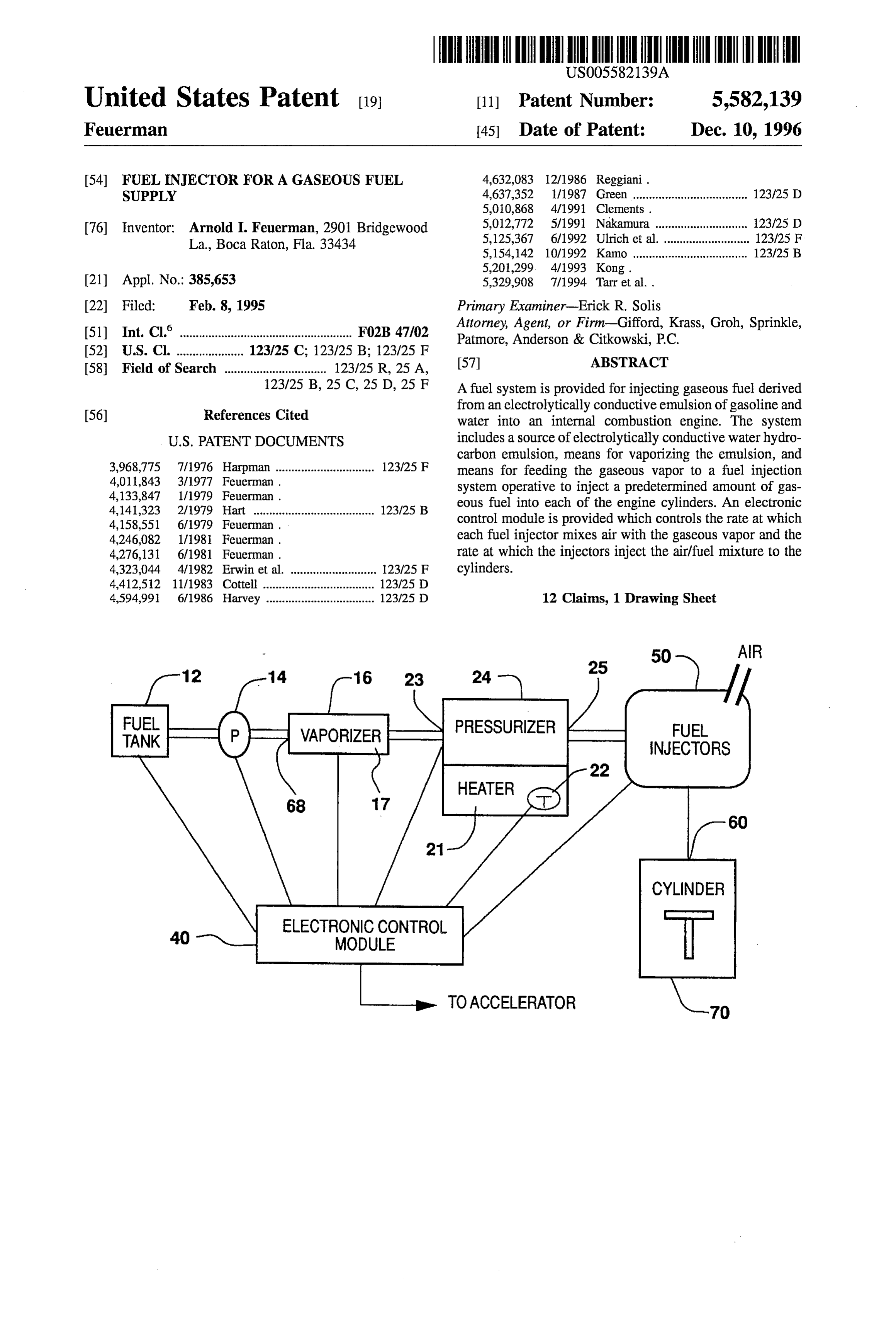
FUEL
NJECTORS
CYLINDER
ELECTRONIC CONTROL
MODULE
TO ACCELERATOR
Page 2
Drawing sheet — no readable text.
Page 3
FUEL INJECTOR FOR A GASEOUS FUEL one or two injectors for all of the engine's cylinders. SUPPLY Multiport fuel injection (MPI) systems feature an injector at each cylinder port. Both TBI and MPI systems inject care
BACKGROUND OF THE INVENTION fully metered bursts of fuel into the engine. MPI systems I. Field of the Invention offer substantial advantages over TBI systems and are typi cally favored in today's engines.
This invention relates generally to a fuel injection system, The great majority of fuel injectors in use today are and more particularly to a method for injecting gaseous fuel designed for injecting liquid fuels to the combustion cham derived from an electrolytically vaporized emulsion of gaso ber. Fuel in the gaseous state exhibits a much lower density line and water into an internal combustion engine. 10 than liquid fuels. Therefore, gaseous fuels must be delivered II. Description of the Relevant Art to the engine at volume flow rates significantly higher than I recognized some time ago a major shortcoming in the liquid fuels. Further, the flow rate of a gaseous fuel must be field of hydrocarbon fueled internal combustion engines. precisely controlled to achieve proper engine performance, Much of the fuel was still in liquid form at the start of the 15 low exhaust emissions, and good fuel economy. Existing combustion chamber explosion despite the fact that both the carburetors and fuel injectors designed for liquid fuels are fuel economy of the engine and the cleanliness of its exhaust not capable of delivering gaseous fuels at the required flow would be improved if the charge were in pure vapor form. rates, and with the needed degree of precision. Since only the vapor derived from the liquid hydrocarbon Gaseous fuel injection systems are known. For example, (usually gasoline) is explosive, any excess unburned hydro U.S. Pat. No. 5,201,299 issued to Kong, discloses a rotary carbon liquid in the combustion chamber substantially 20 gaseous fuel injector for injecting gaseous fuel into an reduces the efficiency of the engine. Therefore, I realized internal combustion engine. U.S. Pat. No. 5,329.908 issued that it would be advantageous to develop a fuel system in to Tarr discloses a natural gas injection system for gaseous which the engine was powered by fuel in the gaseous state. fueled engines.
Through extensive research and development, I invented 25 However, I am not aware of previous fuel injection a unique liquid fuel composition and a novel arrangement systems in which the fuel is liquid at ambient temperatures for vaporizing that fuel to achieve a vapor fuel that would be and pressures and is vaporized and then injected into the provided directly to the combustion chamber. Engines cylinders of an internal combustion engine. fueled by vapor in accordance with my invention attained higher fuel efficiencies than did conventionally fueled SUMMARY OF THE PRESENT INVENTION engines. My invention was disclosed in various forms in my 30 prior patents, U.S. Pat. Nos.: 4,011,843; 4,133,847; 4,158, The present invention broadly contemplates achieving the 551, 4,246,082; and 4,276, 131, advantages provided by utilizing a fuel system in which an One of my patents, U.S. Pat. No. 4,011,843 discloses a electrolytic emulsion of gasoline and water is vaporized and vaporized fuel for an internal combustion engine and a 35 then injected directly to the combustion chamber at a method and apparatus for producing the same. I found that precisely controlled rate.
conventional hydrocarbon fuels such as gasoline could not The above advantages and others are obtained in accor be vaporized even with the addition of electrolytes, since dance with the preferred embodiment by utilizing a fuel electrolytes did not homogeneously mix with gasoline. system combining the benefits of a fuel source consisting of However, the addition of appropriate electrolytes to certain 40 an electrolytically conductive hydrocarbon emulsion with a water-hydrocarbon emulsions produced liquid fuel that plurality of fuel injectors. The electrolytically conductive could be vaporized through the passage of electric current to fuel source used with the invention preferably contains not produce vapor charges containing both hydrocarbons and more than one-third by volume of water. I have determined water. The particular composition of liquid fuel broadly that about 2% to 3% by volume of water is required in the consisted of water-hydrocarbon emulsions with added elec 45 emulsion to attain a vaporizable liquid. The emulsion is trolytes and proved highly stable over all operating condi achieved through the use of relatively small quantities of tions. The increases in fuel economy which resulted from the surfactants. The electrolyte is preferably chosen from the vaporized state of the fuel charge and the presence of water group of mono-basic alkali metal organic compounds having vapor and free hydrogen in the fuel charge outweighed the an alkyl-allyl radical. These compounds are preferably energy consumption of the system vaporizing the fuel, thus 50 modified by the addition of a base such as sodium hydrox increasing the fuel economy of engines fueled in accordance ide, to attain an alkaline nature. Other additives, such as with my invention. dispersants, anticers, anti-rust agents and the like may be I first developed my vaporized fuel system for a carbu combined with the emulsion. The dispersants act to prevent retor based engine. Thus, once the fuel was vaporized, it was agglomeration of the electrolytes, to promote emulsion and provided to a carburetor which mixed the vapor with incom 55 to lower the viscosity. The inventive fuel could also be ing air and provided an explosive charge to the input valves formed by mixing an additive containing the surfactants and of the engine cylinders. The carburetor was controlled by an electrolyte, and water, with gasoline in a fuel tank. accelerator which controlled the charge flow to the cylinders The liquid fuel is first pumped to a vaporizer by a and thus the speed of the engine. Unfortunately, some of the conventional fuel pump. The pump is driven by the engine characteristics of a carburetor based system did not work 60 and provides a stream of fluid from the fuel tank to the well with my invention. vaporizer. The vaporizer passes electric current through fluid Recently, it has become well-known that fuel injection to form a vapor. The resulting vapor includes the vapor from systems offer much greater efficiency than carburetor-based the hydrocarbon, water vapor, and may also contain some systems since the input of fuel to the cylinders may be proportions of molecular hydrogen and oxygen resulting precisely controlled. Modern fuel injection systems are 65 from the electrolytic decomposition of the water and hydro generally divided into two classifications. Throttle body fuel carbons. The passage of current through the liquid fuel to injection (TBI) systems use a central injection point with produce vapor is achieved using a vaporizer of special
Page 4
construction employing closely spaced plates. The vaporizer taining two grams of the sodium sulfate per 100 milliliters is highly efficient both in terms of utilization of electricity of water.
and the current can readily be adjusted to control the rate of The butyl naphthalene sodium sulfonate acts as an elec vapor generation in response to the engine's fuel require entS. trolyte. It is modified by the addition of sodium hydroxide The vapor formed from the fuel is then fed to a pressurizer to provide a basic Ph. It is a member of the class of organic which is preset to maintain a predetermined pressure. The materials known as the mahogany acids. Other mono-basic pressurizer also includes a heating chamber that responds to sulfonates might be employed with other embodiments of low ambient temperatures by heating the vapor to ensure the invention and as a broad class any organic alkaline metal that the vapor remains in the gaseous state. Upon accelera 10 compound that is soluble in the emulsion can be used as an tion by the user, an electronic control module signals a electrolyte.
pressurizer valve to open and force gas into a plurality of fuel injectors. The volume of tap water in the above formula may be varied from 3 to 33% and the balance of the gasoline
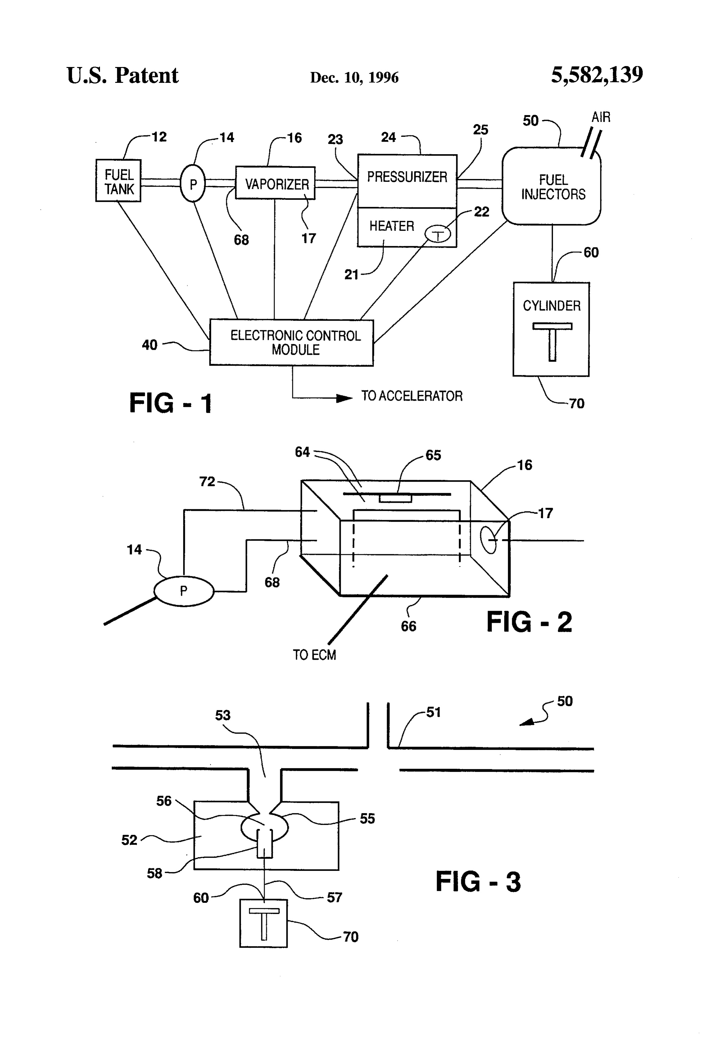
BRIEF DESCRIPTION OF THE DRAWINGS 15 adjusted accordingly without varying the other chemical
Other objectives, advantages and applications of the constituents. Any of these fuels provide satisfactory results. present invention will be made apparent by the following Anti-icers, corrosion resistant agents and other additives detailed description of a preferred embodiment of the inven known to the art may be added as conditions warrant. tion. The description makes reference to the accompanying 20 To combine the ingredients of the above formula the drawings, in which: surfactants are first introduced into the water phase and the FIG. 1 is a schematic block diagram illustrating the fuel gasoline is then added by continuously stirring with an air system for an internal combustion engine in accordance with driven mixing motor at 1,000 rp.m. for 3-10 minutes. It is the present invention; important that as little air as possible be entrained in this FIG. 2 is a schematic drawing of the vaporizer and means 25 emulsion as the thicker mass will require higher pressure for for feeding fuel to the vaporizer; and pumping and air bubbles cause an intermittent fuel flow. FIG.3 is a sectional view through the fuel injector system This emulsion remains stable over long periods with no of the present invention. separation at extremes of temperature and will not freeze if DETAILED DESCRIPTION OF A PREFERRED 30 commonly used gasoline de-icers are used.
EMBODIMENT OF THE PRESENT INVENTION
In FIG. 1, a schematic block diagram of the fuel system EXAMPLE 2. of the present invention is shown. The fuel supply for the engine, stored in the tank 12, broadly comprises a water 35 gasoline emulsion. The water is preferably present in per .60% by volume of butyl naphthalene potassium centages by volume of less than about one-third and in sulfonate .60% by volume of modified potassium sulfonate excess of 2 to 3% by volume. Approximately 26% water .60% by volume of alcohol potassium sulfonate appears to provide optimum engine performance in a con .60% by volume of alkyl terpene ventional automotive engine. I preferably employ fuels of 40 2.80% by volume of butyl ether (Butyl Cellusolve by the following composition in connection with the invention: Union Carbide) 2.80% by volume of alkynolamide (Calamide C by Pilot
Chemical Co.)
EXAMPLE 1 1.00% by volume of ethylene oxide condensate (Macon 4 by Stepan Chemical Co.)
.60% by volume of butyl naphthalenc sodium 67.00% by volume of commercially available gasoline sulfonate (BNS, by Emkay, anionic, modified by sodium hydroxide) 100.00% .60% by volume of modified sodium sulfonate (No.
98, by Petrochem, anionic, dispersant) .60% by volume of alcohol sodium sulfate (Rexowet
NF, by Emkay, anionic) The butyl ether acts as a solvent to provide the emulsion
.60% by volume of alkyl terpene (B, by Emkay, non with a lower viscosity. I have found that the lower the ionic) viscosity of the water-fuel emulsion, the more easily the 25.60% by volume of tap water 72.00% by volume of commercially available gasoline manifold pressure acts to draw the fluid into the vaporizer,
without the need for pumping, thereby achieving a flow which varies in direct proportion to the engine demand.
Similarly, the ethylene oxide condensate acts as a thinner
The alkyl terpene and the alcohol sodium sulfate form the and the alkynolamide acts as an emulsifier. basic surfactant system for emulsifying the water and the The emulsion is best formed by mixing the chemicals gasoline. These surfactants provide a proper hydrophobic 60 with either the gasoline or the water and then mixing in the hydrophilic balance and provide an emulsion having a other component. That is, if the chemicals are first added to higher viscosity than the gasoline which is well suited for use with the preferred embodiments of the vaporizer. the gasoline, the mixture of the chemicals and gasoline is The dispersant is commonly employed with surfactant then added to the water, or vice versa. systems and produces a smooth homogeneous emulsion, 65 The following formula represents an additive intended to preventing agglomeration of the components of the emul be mixed with water and gasoline to form a fuel for use in sion. The modified sodium sulfate is a water solution con connection with the present invention.
Page 5
S 6
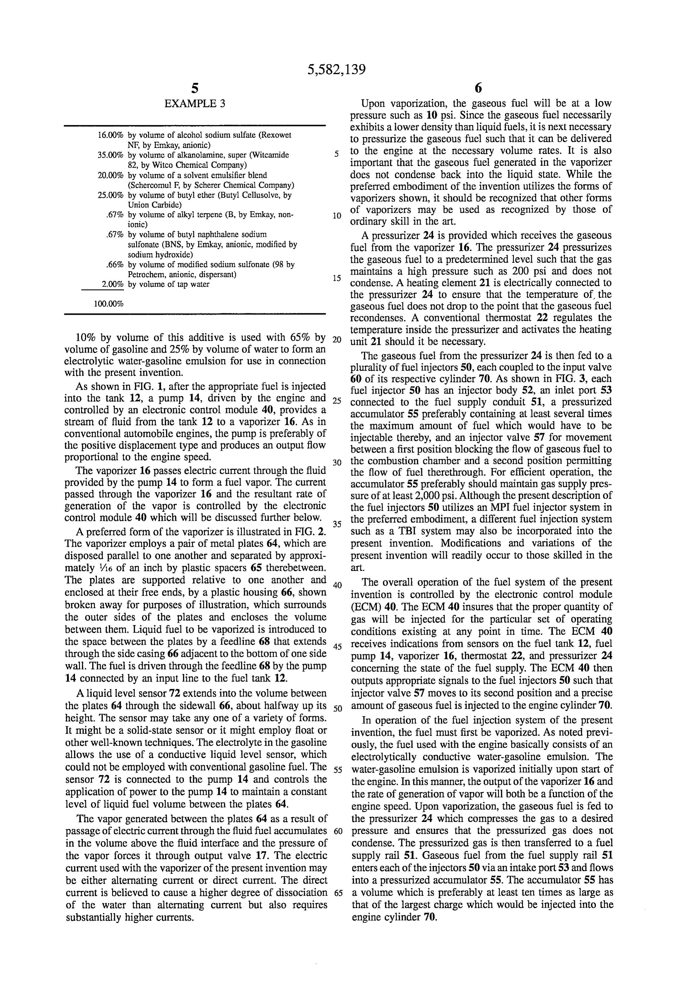
EXAMPLE 3 Upon vaporization, the gaseous fuel will be at a low pressure such as 10 psi. Since the gaseous fuel necessarily exhibits a lower density than liquid fuels, it is next necessary 16.00% by volume of alcohol sodium sulfate (Rexowet to pressurize the gaseous fuel such that it can be delivered NF, by Emkay, anionic) 35.00% by volume of alkanolamine, super (Witcamide to the engine at the necessary volume rates. It is also 82, by Witco Chemical Company) important that the gaseous fuel generated in the vaporizer 20.00% by volume of a solvent emulsifier blend does not condense back into the liquid state. While the (Schercomul F, by Scherer Chemical Company) preferred embodiment of the invention utilizes the forms of 25.00% by volume of butyl ether (Butyl Cellusolve, by vaporizers shown, it should be recognized that other forms Union Carbide) of vaporizers may be used as recognized by those of .67% by volume of alkyl terpene (B, by Emkay, non O ionic) ordinary skill in the art.
.67% by volume of butyl naphthalene sodium A pressurizer 24 is provided which receives the gaseous sulfonate (BNS, by Emkay, anionic, modified by fuel from the vaporizer 16. The pressurizer 24 pressurizes sodium hydroxide) the gaseous fuel to a predetermined level such that the gas .66% by volume of modified sodium sulfonate (98 by
maintains a high pressure such as 200 psi and does not 2.00% by volume of tap water condense. A heating element 21 is electrically connected to
the pressurizer 24 to ensure that the temperature of the gaseous fuel does not drop to the point that the gaseous fuel recondenses. A conventional thermostat 22 regulates the temperature inside the pressurizer and activates the heating 10% by volume of this additive is used with 65% by unit 21 should it be necessary. volume of gasoline and 25% by volume of water to form an The gaseous fuel from the pressurizer 24 is then fed to a electrolytic water-gasoline emulsion for use in connection plurality of fuel injectors 50, each coupled to the input valve with the present invention. 60 of its respective cylinder 70. As shown in FIG. 3, each As shown in FIG. 1, after the appropriate fuel is injected fuel injector 50 has an injector body 52, an inlet port 53 into the tank 12, a pump 14, driven by the engine and 25 connected to the fuel supply conduit 51, a pressurized controlled by an electronic control module 40, provides a accumulator 55 preferably containing at least several times stream of fluid from the tank 12 to a vaporizer 16. As in the maximum amount of fuel which would have to be conventional automobile engines, the pump is preferably of injectable thereby, and an injector valve 57 for movement the positive displacement type and produces an output flow between a first position blocking the flow of gaseous fuel to proportional to the engine speed. 30 the combustion chamber and a second position permitting The vaporizer 16 passes electric current through the fluid the flow of fuel therethrough. For efficient operation, the provided by the pump 14 to form a fuel vapor. The current accumulator 55 preferably should maintain gas supply pres passed through the vaporizer 16 and the resultant rate of sure of at least 2,000 psi. Although the present description of generation of the vapor is controlled by the electronic the fuel injectors 50 utilizes an MPI fuel injector system in control module 40 which will be discussed further below.
35 the preferred embodiment, a different fuel injection system
A preferred form of the vaporizer is illustrated in FIG. 2. such as a TBI system may also be incorporated into the The vaporizer employs a pair of metal plates 64, which are present invention. Modifications and variations of the disposed parallel to one another and separated by approxi present invention will readily occur to those skilled in the mately /16 of an inch by plastic spacers 65 therebetween. art.
The plates are supported relative to one another and 40 The overall operation of the fuel system of the present enclosed at their free ends, by a plastic housing 66, shown invention is controlled by the electronic control module broken away for purposes of illustration, which surrounds (ECM) 40. The ECM 40 insures that the proper quantity of the outer sides of the plates and encloses the volume gas will be injected for the particular set of operating between them. Liquid fuel to be vaporized is introduced to conditions existing at any point in time. The ECM 40 the space between the plates by a feedline 68 that extends 45 receives indications from sensors on the fuel tank 12, fuel through the side casing 66 adjacent to the bottom of one side pump 14, vaporizer 16, thermostat 22, and pressurizer 24 wall. The fuel is driven through the feedline 68 by the pump concerning the state of the fuel supply. The ECM 40 then 14 connected by an input line to the fuel tank 12. outputs appropriate signals to the fuel injectors 50 such that A liquid level sensor 72 extends into the volume between injector valve 57 moves to its second position and a precise the plates 64 through the sidewall 66, about halfway up its 50 amount of gaseous fuel is injected to the engine cylinder 70. height. The sensor may take any one of a variety of forms. In operation of the fuel injection system of the present It might be a solid-state sensor or it might employ float or invention, the fuel must first be vaporized. As noted previ other well-known techniques. The electrolyte in the gasoline ously, the fuel used with the engine basically consists of an allows the use of a conductive liquid level sensor, which electrolytically conductive water-gasoline emulsion. The could not be employed with conventional gasoline fuel. The 55 water-gasoline emulsion is vaporized initially upon start of sensor 72 is connected to the pump 14 and controls the the engine. In this manner, the output of the vaporizer 16 and application of power to the pump 14 to maintain a constant the rate of generation of vapor will both be a function of the level of liquid fuel volume between the plates 64. engine speed. Upon vaporization, the gaseous fuel is fed to The vapor generated between the plates 64 as a result of the pressurizer 24 which compresses the gas to a desired passage of electric current through the fluid fuel accumulates 60 pressure and ensures that the pressurized gas does not in the volume above the fluid interface and the pressure of condense. The pressurized gas is then transferred to a fuel the vapor forces it through output valve 17. The electric supply rail 51. Gaseous fuel from the fuel supply rail 51 current used with the vaporizer of the present invention may enters each of the injectors 50 via an intake port 53 and flows be either alternating current or direct current. The direct into a pressurized accumulator 55. The accumulator 55 has current is believed to cause a higher degree of dissociation 65 a volume which is preferably at least ten times as large as of the water than alternating current but also requires that of the largest charge which would be injected into the substantially higher currents. engine cylinder 70.
Page 6
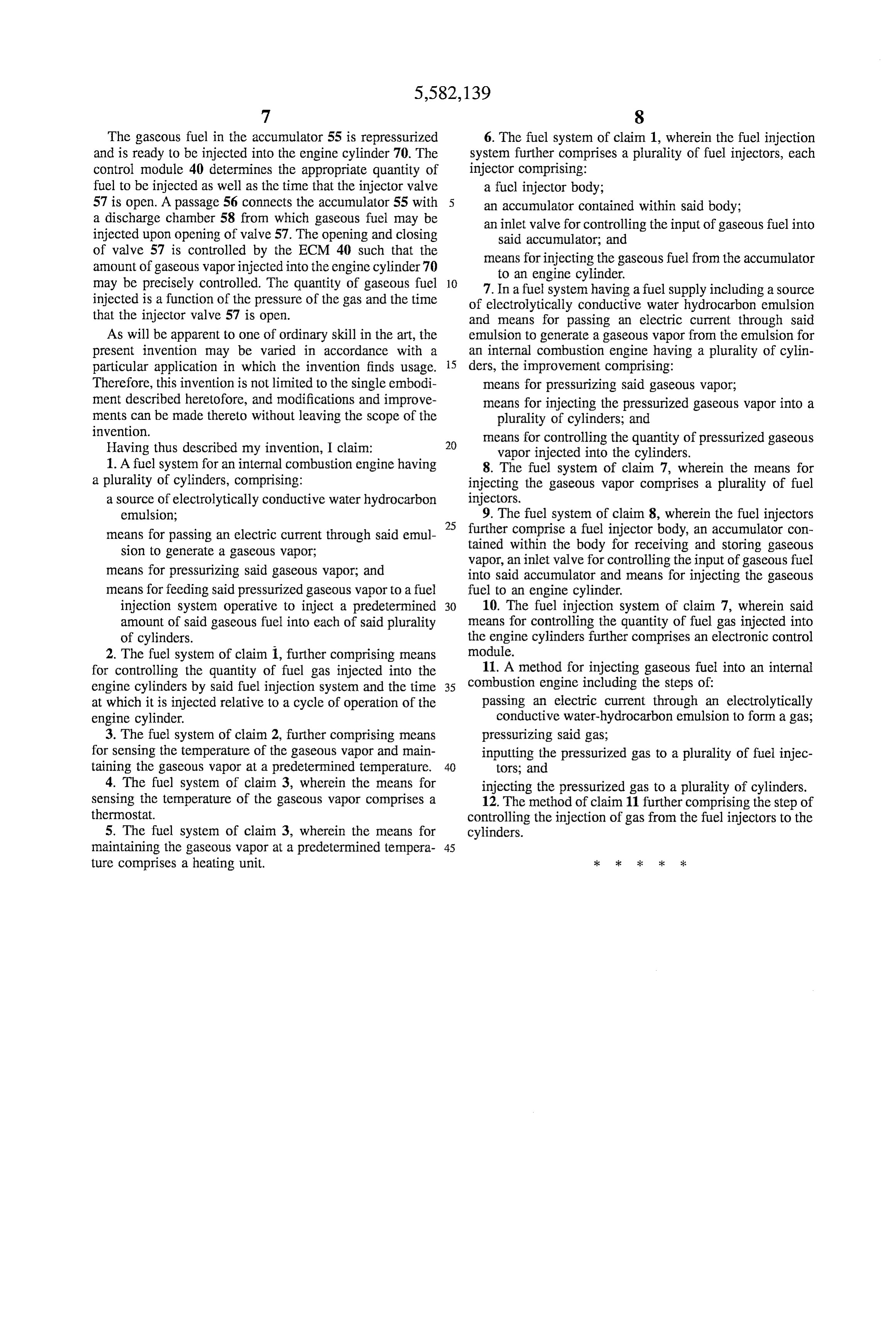
The gaseous fuel in the accumulator 55 is repressurized 6. The fuel system of claim 1, wherein the fuel injection and is ready to be injected into the engine cylinder 70. The system further comprises a plurality of fuel injectors, each control module 40 determines the appropriate quantity of 1njector comprising:
fuel to be injected as well as the time that the injector valve a fuel injector body;
57 is open. A passage 56 connects the accumulator 55 with an accumulator contained within said body; a discharge chamber 58 from which gaseous fuel may be an inlet valve for controlling the input of gaseous fuel into injected upon opening of valve 57. The opening and closing Said accumulator, and of valve 57 is controlled by the ECM 40 such that the means for injecting the gaseous fuel from the accumulator amount of gaseous vapor injected into the engine cylinder 70 may be precisely controlled. The quantity of gaseous fuel 10 7. to an engine cylinder.
In a fuel system having a fuel supply including a source injected is a function of the pressure of the gas and the time of electrolytically conductive water hydrocarbon emulsion that the injector valve 57 is open. and means for passing an electric current through said As will be apparent to one of ordinary skill in the art, the emulsion to generate a gaseous vapor from the emulsion for present invention may be varied in accordance with a an internal combustion engine having a plurality of cylin particular application in which the invention finds usage. 15 ders, the improvement comprising:
Therefore, this invention is not limited to the single embodi means for pressurizing said gaseous vapor; ment described heretofore, and modifications and improve means for injecting the pressurized gaseous vapor into a ments can be made thereto without leaving the scope of the plurality of cylinders; and invention. means for controlling the quantity of pressurized gaseous Having thus described my invention, I claim: 20 vapor injected into the cylinders.
1. A fuel system for an internal combustion engine having 8. The fuel system of claim 7, wherein the means for a plurality of cylinders, comprising: injecting the gaseous vapor comprises a plurality of fuel a source of electrolytically conductive water hydrocarbon injectors.
emulsion; 9. The fuel system of claim 8, wherein the fuel injectors 25 further comprise a fuel injector body, an accumulator con means for passing an electric current through said emul tained within the body for receiving and storing gaseous Sion to generate a gaseous vapor, vapor, an inlet valve for controlling the input of gaseous fuel means for pressurizing said gaseous vapor; and into said accumulator and means for injecting the gaseous means for feeding said pressurized gaseous vapor to a fuel fuel to an engine cylinder.
injection system operative to inject a predetermined 30 10. The fuel injection system of claim 7, wherein said amount of said gaseous fuel into each of said plurality means for controlling the quantity of fuel gas injected into of cylinders. the engine cylinders further comprises an electronic control 2. The fuel system of claim 1, further comprising means module.
for controlling the quantity of fuel gas injected into the 11. A method for injecting gaseous fuel into an internal engine cylinders by said fuel injection system and the time 35 combustion engine including the steps of: at which it is injected relative to a cycle of operation of the passing an electric current through an electrolytically engine cylinder. conductive water-hydrocarbon emulsion to form a gas; 3. The fuel system of claim 2, further comprising means pressurizing said gas;
for Sensing the temperature of the gaseous vapor and main inputting the pressurized gas to a plurality of fuel injec taining the gaseous vapor at a predetermined temperature. 40 tors; and 4. The fuel system of claim 3, wherein the means for injecting the pressurized gas to a plurality of cylinders. sensing the temperature of the gaseous vapor comprises a 12. The method of claim 11 further comprising the step of thermostat. controlling the injection of gas from the fuel injectors to the 5. The fuel system of claim 3, wherein the means for cylinders.
maintaining the gaseous vapor at a predetermined tempera 45 ture comprises a heating unit.
Provenance
- Collection
- Cited prior art
- Original PDF
- patentimages.storage.googleapis.com →
- Filed
- 1995-02-08
- Pages
- 6
- Method
- pdftotext (the PDF's own text layer) + pdftoppm 300dpi page scans
- Source
- Google Patents bibliographic record
- Granted
- 1996-12-10
- Inventors
- Arnold I. Feuerman
- Transcribed from
- patentimages.storage.googleapis.com →